1’000’000 amperes deram cell

Author: Kaenel Rene V., Antille Jacques, Bugnion Louis, Kaenel Laure V.
Journal: Журнал Сибирского федерального университета. Серия: Техника и технологии @technologies-sfu
Article in issue: 6 т.9, 2016.
Free access
The aluminum industry is constantly looking at reducing the production cost. During the last three decades it has mainly been achieved by the economy of scale consisting in increasing the cell dimensions allowing for higher current and therefore increasing the plant production and productivity. This paper presents under which conditions a step change can be achieved without increasing the shell dimensions. The design of a cell of the future is discussed in term of voltage distribution, heat loss, energy saving, productivity and environmental consequences.
High productivity, low specific energy, low emissions
Short address: https://sciup.org/146115113
IDR: 146115113 | UDC: 669.71:621.357.13 | DOI: 10.17516/1999-494X-2016-9-6-802-810
Электролизер мечты: 1’000’000 ампер
Алюминиевая промышленность постоянно изыскивает способы снижения производственных затрат. За последние три десятилетия это было достигнуто за счет экономии масштабов, при этом размеры электролизера были увеличены, что позволило применять более высокую силу тока для увеличения объемов производства и производительности. В статье обсуждается вопрос, при каких условиях можно достичь качественного изменения без увеличения размеров кожуха. Обсуждается конструкция электролизера будущего с точки зрения распределения напряжения, тепловых потерь, экономии энергии, производительности и экологических последствий.
Text of the scientific article 1’000’000 amperes deram cell
During the last three decades, the line current in aluminium reduction plants has increased considerably and has reached 600 kA. During the same period all smelters have been active at increasing the productivity in their existing shell by increasing the anode size and the anode current density. This was achieved by better cathode and collector bars designs sometimes combined with busbars modifications to improve the cell magneto-hydrodynamic stability. A better magneto-hydrodynamic cell state allows decreasing the anode to cathode distance (ACD) needed for achieving the right thermal balance. If the cell productivity is expressed as tons produced per year and square meter inside a given shell, the increase have proven to be in the range of 10 to 30%. In the best case it has reached 80% depending on the initial state of the cell technology and level of optimization. During the same period the current efficiency has also improved and the best technologies achieve results close to 96%. When analyzing the evolution of the specific energy consumption ( E ), a decrease from above 14 kWh/kg to 13 kWh and lower was achieved in many smelters. The theoretical energy consumption can be expressed as:
E = 1.431 / η + 4.915 [kWh/kg] (1)
where η is the current efficiency. The energy efficiency is the ratio of the needed energy to the used energy. The energy efficiency of the Hall-Héroult process is low as shown in Table 1. It was increased from about 43% to 48% over 30 years and has hardly reached 50% in the best cases.
It is reasonable to ask ourselves what can be done to further improve the plant productivity. Should we double the length of the cell to double the current? Would it help at increasing the energy efficiency and current efficiency? Knowing that today high amperage cells are in the range of 20 meters in length, doubling the length does not seem to be reasonable. Increasing the width appears also as a challenge for the magneto-hydrodynamic cell stability and for the anode length and weight. Not to be forgotten, for every kilo of aluminum produced more than one kilo carbon-dioxide and about hundred grams of carbon monoxide are produced. With sixty millions tons of aluminum produced every year it is not negligible.
So what can be done?
Table 1. Hall-Héroult process energy efficiency
|
Current efficiency, % |
Specific energy, kWh/kg |
Energy efficiency, % |
|
94 |
6.26 |
100 |
|
94 |
15.00 |
41.7 |
|
94 |
14.00 |
44.7 |
|
94 |
13.00 |
48.2 |
|
94 |
12.00 |
52.2 |
|
94 |
11.00 |
56.9 |
|
94 |
10.00 |
62.6 |
The cell of the future
The cell of the future should satisfy our dreams, however realistic dreams, such as:
-
- High productivity: more than double than today
-
- Low specific energy consumption: lower than 12 kWh/kg
-
- High current efficiency: higher than 95%
-
- High volume of bath/kA: higher chemical stability
-
- Low bath temperature: higher current efficiency
-
- Lower energy
Is it a dream or does it make sense?
How can we achieve these performances?
The authors see no possibilities to achieve such a dream with the existing carbon anodes, but, when using metallic anodes [1], many possibilities of redesigning the cell are coming up. In this paper the authors have analyzed what looks very promising to their point of view. Table 2 challenges the parameters of a dreaming cell to an existing cell technology.
The table speaks by itself but let us comment the important parameters. The productivity is increased by a factor 2.8. This was never achieved before. The specific energy consumption is lower than 12 kWh/kg. This is remarkable and contradicts many beliefs stating that the “inert anode” has to pay one extra volt and therefore will produce with about 3 kWh/kg increase of specific energy. The result is of course linked to the design shown after. The current efficiency is shown as 96%. This cannot be calculated with accuracy but is more an assumption linked to the fact that the anode to cathode distance is constant in the dream cell and the amount of bath is more than ten times bigger for every kA in the
Table 2. Comparison between an existing technology and “A dream cell”
Figure 1 shows the reference carbon anode. Figure 2 shows how the metallic anode has a surface of 2.8 times the surface of the carbon anode. Figure 3 shows the metallic anode. This is where the miracle takes place. Due to the dimension stability of the anodes and the high conductivity of metallic anodes, the geometry can be fully revisited. The average current density is almost kept constant but the electrical circuit is fully revisited. The average anode current density is 0.865 A/cm2 for the carbon. The cell current is 0.865 ∙ 160 ∙ 65 ∙ 40 = 360’000 A. For the metallic anode the surface is multiplied by 2.8 so the current can be 1’000’000 A.
Cell thermal-electrical model
Table 3 summarizes the voltage breakdown of both technologies. The external voltage is assumed to be the same for both. This can be achieved by using adequate busbars sections. The anode voltage drop is 160 mV lower for the metallic anode due to the higher conductivity of the assumed Ni-Fe metallic structure compared to the carbon anode. No anode effects are expected to
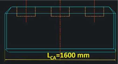
Fig. 1. Carbon anode
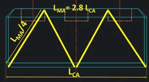
Fig. 2. Concept for the surface for the metallic anode
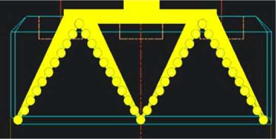
Fig. 3. Example of metallic anode geometry
Table 3. Voltage breakdown
Table 4 shows the energy aspects of both technologies. It can be observed that the global energy efficiency is better, the internal heat of both technologies is very similar. This means that a similar thermal equilibrium can be found leading to a similar ledge shape. The specific energy of the metallic anode technology is 11.73 kWh/kg which is lower than any standard Hall-Héroult existing cell. This shows that metallic anodes can be competitive to the carbon anodes when used with the Hall-Héroult process if the cell design is adequate.
Table 5 shows an example of bath that could be used for both technologies. The use of lithium is important to decrease the bath resistivity to compensate for the addition of potassium fluoride needed
Table 4. Energy aspects
|
How to make a dream come true 1’000’000 A cell |
|||
|
Unit |
Reference |
Vision |
|
|
Modern Hall-Heroult technology |
Future Hall-Heroult technology |
||
|
Specific energy Hall-Heroult process |
|||
|
External heat |
kWh/kg |
0.73 |
0.71 |
|
Internal heat |
kWh/kg |
5.67 |
1.76 |
|
Energy to produce metal |
kWh/kg |
6.44 |
9.26 |
|
Total |
kWh/kg |
12.84 |
11.73 |
|
Energy efficiency (theoretical/used energy) |
% |
48.8 |
53.6 |
|
Power Hall-Heroult process |
|||
|
External heat |
KW |
82.8 |
230.0 |
|
Internal heat |
KW |
644.2 |
566.3 |
|
Energy to produce metal |
KW |
731 |
2984 |
|
Total |
KW |
1458 |
3780 |
Table 5: Bath properties
To demonstrate the feasibility a full three dimensional model was realized based on a 360 kA cell.
The coupled thermal-electrical problem was solved. Figure 4 shows the cell geometry.
Figure 5 shows a vertical section th r ough the cell showing the anode shape, the graphite wettable cathode and the level of the liquid metal before tapping.
Figure 6 shows ¼ anode geometry. This geometry could further be improved to minimize the voltage drop but this was not considered in the scope of this paper.
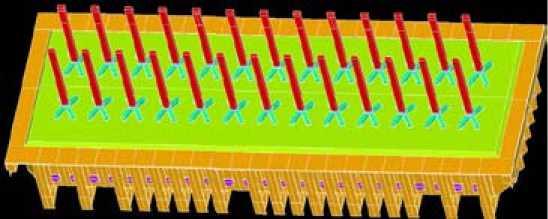
Fig. 4. 3D model of 1’000’000 A cell
Anode
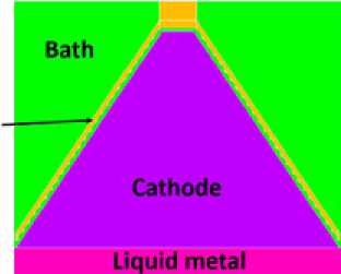
Cathode
Bath
Liquid metal
Fig. 5. Vertical section through the cell showing ½ of one anode
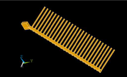
Fig. 6. Geometry of ¼ anode
Figure 7 shows the electrical potential in the distance from the entrance of the anode to the liquid metal for ¼ of one anode. The voltage is equal to 1.013 V which is very much in line with the targeted voltage given in Table 3. Indeed, the ohmic voltage drop should be 0.1+0.063+0.847= 1.010 V.
The current density in the same ¼ anode is shown in Fig. 8.
Figure 9 shows the current density inside the bath. It can be observed that the average value over the surface is about 2 A/cm2. In average it remains 0.865 A/cm2 but is increased locally due to the “finger” geometry.
By looking locally around one anode finger (Fig. 10), one can see that the current density is varying between about 0.6 A/cm2 to 2.8 A/cm2 maximum. This could be improved drastically by searching for better anode shapes and would lead to even lower voltage drop. In the frame of this feasibility study it was not necessary as the cell shows already much better figures than the carbon anode cell.
Conclusions
Under the assumptions that:
-
- A metallic anode is available with an economical life (must not be inert forever!)
-
- A wettable cathode is available for draining the metal for a few years a cell can be designed with:
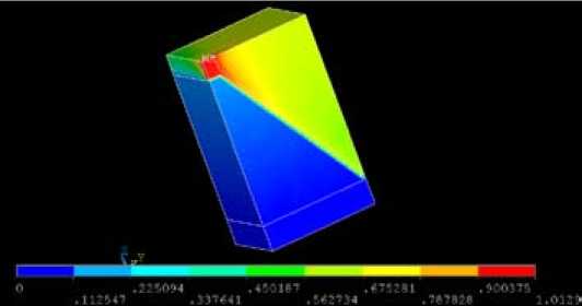
Fig. 7. Electrical potential in ¼ anode (V)
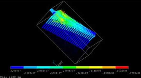
Fig. 8. Current density in ¼ anode (A/m2)
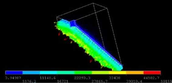
Fig. 9. Current density in ¼ area of the bath (A/m2)
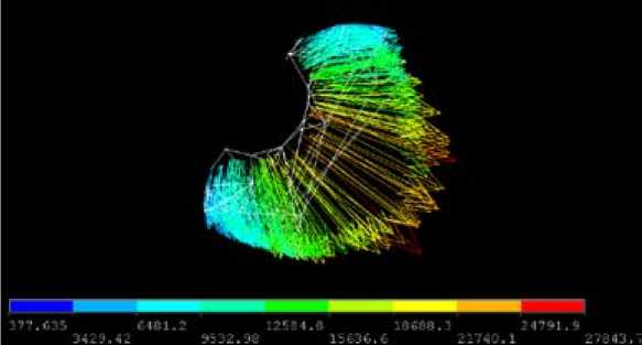
Fig. 10. Current density around one anode “finger” (A/m2)
-
- More than double productivity than today
-
- Lower than 12 kWh/kg specific energy consumption
-
- Higher than 95% current efficiency
-
- Better economical results than today’s technology
In other words, the dream is not unrealistic as was demonstrated by performing thermal-electrical calculations.
References 1’000’000 amperes deram cell
- Antille J., Klinger L., Von Kaenel R., de Nora V. Modelling of a 25 kA De Nora inert metallic anode test cell, Light Metals, 2006, 391-396
