5G small cell backhaul: a solution based on GSM-aided hybrid beamforming

Author: Olabode Idowu-Bismark, Oluseun Oyeleke, Aderemi A. Atayero, Francis Idachaba
Journal: International Journal of Computer Network and Information Security @ijcnis
Article in issue: 8 vol.11, 2019.
Free access
In the proposed 5G architecture where cell densification is expected to be used for network capacity enhancement, the deployment of millimetre wave (mmWave) massive multiple-input multiple-output (MIMO) in urban microcells located outdoor is expected to be used for high channel capacity small cell wireless traffic backhauling as the use of copper and optic-fibre cable becomes infeasible owing to the high cost and issues with right of way. The high cost of radio frequency (RF) chain and its prohibitive power consumption are big drawbacks for mmWave massive MIMO transceiver implementation and the complexity of using optimal detection algorithm as a result of inter-channel interference (ICI) as the base station antenna approaches large numbers. Spatial modulation (SM) and Generalized Spatial Modulation (GSM) are new novel techniques proposed as a low-complexity, low cost and low-power-consumption MIMO candidate with the ability to further reduce the RF chain for mmWave massive MIMO hybrid beamforming systems. In this work, we present the principles of generalized spatial modulation aided hybrid beamforming (GSMA-HBF) and its use for cost-effective, high energy efficient mmWave massive MIMO transceiver for small cell wireless backhaul in a 5G ultra-dense network.
5G, Antenna array, Small Cell Backhaul, Spatial Modulation, mmWave massive MIMO
Short address: https://sciup.org/15015707
IDR: 15015707 | DOI: 10.5815/ijcnis.2019.08.03
Text of the scientific article 5G small cell backhaul: a solution based on GSM-aided hybrid beamforming
Published Online August 2019 in MECS DOI: 10.5815/ijcnis.2019.08.03
Multiple input multiple output (MIMO) technology is a technique of using multiple antennas at the transmitter and the receiver to transmit many data symbols at the same time instant in order to achieve spectral efficiency, reduce transmit power per antenna, increase data rate and link reliability with minimum error rate [1, 2]. This was motivated by the need to provide better ways of meeting the demand for a continuous data rate increase in the cellular industry due to the advent of mobile smartphones, tablets, and laptops with applications for video streaming, live coverage transmissions, vehicle-to-infrastructure, augmented reality video streams, etc. Some of the challenges imposed by massive MIMO systems in mmWave frequency bands despite its numerous advantages include the receiver complexity due to interchannel interference (ICI), increase in pilot overhead for channel state information (CSI) as the number of transmit antennas increases to large number and the increase in static power as well as cost of the Base station (BS) due to increase in the radio frequency (RF) chain with its associated mixers, power amplifiers, filters etc leading to increase in the operational cost of the base stations as well as power inefficiency of the transmission system [1]. The above has posed a challenge in the cost-effective and energy efficient deployment of massive MIMO in the proposed fifth generation (5G) communication networks. Hybrid beamforming is a solution to the above problem by minimizing the high cost and complexity of hardware implementation in millimeter wave (mmWave) massive MIMO. In hybrid beamforming, rather than have an RF chain per antenna element, the transmit antennas are divided into sub-arrays with analog beamforming using phase shifters at RF and digital baseband precoding for flexibility per sub-array thereby reducing the employed RF chains leading to reduced static power usage and increased energy efficiency of the system [3].
The spatial modulation (SM) MIMO otherwise called single-RF MIMO technique takes this solution further by employing only one antenna at a modulation instant from an array of transmit antennas thereby eliminating ICI as well as reducing the receiver complexity due to ICI [1, 2]. According to [5, 6] aside from the conventional M-ary signal constellation technique of transmitting information, SM transmits information also by means of the indices of the active transmit antenna. Here additional information bits are mapped onto the spatial domain of the two dimensional (2D) signal constellation thereby creating the three dimensional (3D) constellation diagram which produces a MIMO implementation with reduced signal processing and circuitry complexity and an improved energy efficiency ideal for deployment in a massive MIMO scenario [5].
The use of wireless backhaul for small cells require a high data rate that can be offered by mmWave frequencies from 30GHz - 300GHz due to its availability of wider bandwidth. However, there are major issues with its implementation which include high pathloss, severe penetration loss and the fact that the resulting channel is poorly scattered [8, 9]. Massive MIMO employing hybrid beamforming with large scale antennas at the BS offers a solution to the above challenges due to its ability to compensate for the high large-scale fading within the mmWave frequency channel [7]. The affiliation involving mmWave and massive MIMO has led to the concept of mmWave massive MIMO [8]. Thus, with the small wavelength of mmWave, large number of antennas can be packed within a small form factor to provide higher spectral efficiency and at the same time, the beamforming technique available with a large number of antenna elements can mitigate the pathloss of mmWave channels, enhance SINR with improved quality of service (QoS) [9]. Although, mmWave massive MIMO constitute a promising candidate for the proposed 5G cell densification technique of increasing the network capacity [10], it comes with its own challenges including space issue required for large number of miniaturized RF chain needed per antenna element or antenna array packed within a small space and the resulting huge heat dissipation leading to difficult hardware implementation [9] which the combination of hybrid beamforming and SM-MIMO can adequately resolve. Other challenges include the characterization of the new mmWave massive MIMO channel and the provision of channel models for predicting the performance of the system [11] which are outside the scope of this paper.
-
II. Related Works
As a result of the low-RF-chain nature of SM techniques and other benefits that it offers, the incorporation of SM with hybrid beamforming to further reduce the static power of the BS and the complexity of the receiver has recently attracted the academia attention [4,5,9,14,15]. With this combination, on one hand, SM with the aid of its random antenna switching ability, a better trade-off can be achieved between SE and the required RF chain while on the other hand, mmWave massive MIMO hybrid beamforming can improve the
SINR and data rate performance of SM [8]. This SM-aided hybrid beamforming (SMA-HBF) concept can offer a good and cost-effective way of providing wireless backhaul for small cells in an ultra-dense network in order to achieve high network capacity.
Several works have considered SMA-HBF including [9,16,17] where computational efficient MIMO hybrid precoding was designed for generalized SM-aided mmWave MIMO while [7] went a step further by designing a digital combining at the receiver. The author in [3] used SMA-HBF for 5G high-speed train critical safety signalling and passenger internet access communication. Other works in SM-aided massive MIMO at classical frequency include the work of [12] where the spectral efficiency of the system is compared with conventional massive MIMO. In [13], the authors took advantage of the structure and sparsity of the transmitted SM signals to enhance the performance of the detection algorithm for massive MIMO system, while similar works were done by the authors of [14] which considered the use of local search and message passing algorithms for signal detection in massive SM-MIMO and [15] which considered maximum likelihood algorithm for SM-MIMO. The uplink bandwidth efficiency of multi-user massive SM-MIMO system was derived in [16] while [17] established that SM has major SNR improvement over classical modulation in massive MIMO.
The aim of this work is to present the principles of generalized spatial modulation for mmWave massive MIMO hybrid beamforming needed for 5G wireless small cell backhaul. We analyzed the energy and cost efficiency of the conventional hybrid BF and GSM-aided hybrid BF technologies and draw conclusions. The remaining part of this paper is arranged thus. Section II considers the requirement for wireless backhaul in small cell UDN and in Section III we offer a prologue to the ideology of SM/GSM practice, which is essential for appreciating the design principle of GSM-aided mmWave massive MIMOs. Section IV treated the types of SM-aided mmWave-MIMO schemes available while we looked at the GSM-aided Hybrid Beamforming Model in section V. We carried out the implementation of the GSM-aided Hybrid Beamforming scheme needed for the small cell backhaul in section VI and draw a conclusion in section VII.
-
III. Small Cell Wireless Backhaul in UDN
The deployment of dense small cells (SCs) in 5G networks require the use of wireless backhaul to adequately connect the small cells to the macro cell BS or the core network (CN) as shown in figure 1 and guarantee the required throughput inside the small cell [24,25]. 3GPP committee on standards suggested wireless solutions for backhauls in small cells using microwave connections in LOS/NLOS situations and mmWave connections in LOS situations [19]. Cell sizes will shrink in 5G making the use of wireless backhaul more important based on cost and right of way considerations.
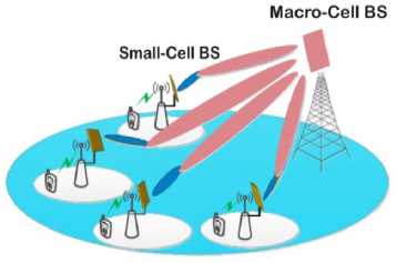
Fig.1. Small cells wireless backhaul links
According to [20] realizing the point-to-multipoint (P2M) small cell backhaul link requires that UDN exploit the flexibility of 3D beamforming offered by mmWave massive MIMO in order to sustain many small cells with multiple streams which the current conventional precoding/combining schemes are incapable of supporting. While the conventional mmWave multipleantenna system uses a single RF chain with phaseshifters for analogue beamforming (precoding) which limit it to single user MIMO as shown in figure 2.
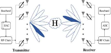
Fig.2. Analog Beamforming
The microwave massive MIMO with fully digital beamforming as shown in figure 3, support multiuser MIMO but requires an RF chain per antenna making it very expensive and the user's equipment apply one or two-antennas which may not be adequate to provide high data needed by the small cell.
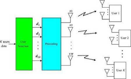
Fig.3. MU-MIMO using Digital Beamforming
UDN with small cells deploying mmWave massive MIMO for cell backhaul may, therefore, require new high complexity hybrid precoding/combining scheme (figure 4) at both the BS and the small cell. One way of reducing the complexity of this precoding/combining scheme is the use of Generalized SM scheme for downlink hybrid precoding (beamforming) at both the BS and SM scheme for uplink combining at the small cell [20].
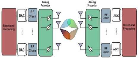
Fig.4. Hybrid Beamforming
The authors of [21] allege that the macrocell BS in 5G ultra-dense networks is only designed to broadcast the supervision data which controls the handover of users as they move from one small cell to another while the small cells handle the user data transmission. Thus, the small cell network requires an independent backhaul capability that only dedicated wireless connections can provide as the backhaul functions are not complementary to the macrocell network. The authors of [22] discussed many backhaul solutions including wired and wireless. According to the authors in [20], in the proposed UDN, SCs are closely installed in offices, shopping centres, etc with high data rate in order to offer traffic offload from macrocells, since the buck of traffic usage comes from these hotspots. Therefore, small cells wireless backhaul should be reliable with high throughput, power efficient and be cost efficient in its deployment for operators.
-
IV. Sm And Generalized SM Techniques
Spatial modulation has a lot of advantages over the classical MIMO system in that it uses simple transceiver design employing one RF chain for its transmission where the transmitter power does not depend on the number of antennas deployed thereby making it an energy efficient technology. With SM, inter-antenna synchronization (IAS) and inter-channel interference (ICI) are entirely done away with and the complexity of the receiver in decoding the received symbols, in terms of mathematical computations performed, increases in a linear dimension as the constellation size increases and the number of transmitting antennas increases. Again, in SM the number of receive antennas is not restricted as we have in V-BLAST scheme, which requires nr > Nt before the minimum mean square error (MMSE) detector can be operational [23]. Finally, SM has a higher spectral efficiency than single-input single-output (SISO) and orthogonal STC systems due to the employment of antenna indices as an additional source of information, [24].
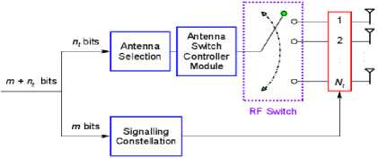
Fig.5. SM-MIMO Transmitter Schematic Diagram
In spatial modulation, the information symbols to be transmitted are divided into two. While one part is encoded onto the signal constellation diagram for transmission, that is the log2( м ) bits of the sequence are employed to modulate the carrier signal and the other data part transmission takes place through the information-driven transmit antenna switching mechanism where log2 N у bits of the sequence are used to select the index (I) of the actual transmitting antenna which executes the transmission of the corresponding modulated signal (S) [1,6] as shown in diagram 4. (m = log2 Nr and Ny = 2 ) The signal transmitted from the active transmit antenna (or group of antennas) then propagate through the wireless channel and because of the different spatial locations of the various transmit antennas, each transmits signal symbol experience different propagation conditions as a result of the different reflectors, scatterers, etc along its path as it moves from the transmitter to the receiver. These different interactions with different scatterers leading to different travel paths introduce different ‘‘channel signature'' to each signal symbol's channel impulse response that make it unique from the same symbol but from different transmit antenna that goes through a different channel path. The more unique the channel signature, the easier it is for the receiver to distinguish the various signals [1]. For every signaling interval, the transmission rate is given in equation 1
log2 NT + log 2M (1)
At the receiver, for us to detect the symbols transmitted, the receiver using CSI must know a priori the CIRs of all the Tx-Rx wireless links and in general, a total of NrNt CIR need to be estimated and using the maximum likelihood algorithm [23] rule is given in equation 2
̂ ML=argmin ‖У - н x ǁ (2)
x∈ А 7 v } assuming that our received signal model at the BS is given as Y= +V where the ML detector has to conduct a joint search over all transmit antenna and constellation symbols by computing the Euclidean distance of mnrnt between the receiver signal and the set of possible signals modulated by the wireless channel in such a way that we can decode all the bits in the transmitted block and recover the original bit-stream [14].
Generalized spatial modulation (GSM) unlike SM, activates more than one transmit antenna per transmission period [25]. The number of transmit RF chains in GSM, Nrf is greater than 1 but less than the total number of transmit antennas Ny and in a given channel use ^RF out of Nj are chosen and activated while the remaining Nr - ^RF antennas are silent within this period [26]. This way the number of Ny required to achieve the same spectral efficiency in SM is reduced by more than half in GSM. Unlike SM, GSM offers spatial diversity gain as well as increased channel reliability by providing transmitted signal replicas at the receiver [32,34].
According to [1], the GSM-MIMO is not necessarily a rival MIMO method in the LTE-A standard, rather it should be considered as an improvement toward spectral and energy efficient 5G cellular networks. It was stated that by switching off the spatial-constellation diagram of the GSM-MIMO transceiver, it reduces to the spacetime-coding transmission of the LTE-A while “switching on” the spatial-constellation diagram improve the system throughput, improve the power efficiency without transmitter/receiver complexity [1]. In GSM-MIMO, on the selected antennas, ^RF modulation symbols (one per selected antenna) are transmitted while the indices of the Nrf active antennas out of the total NT antennas transport ⌊ log2( N ) ⌋ information bits. In addition to this, Nrf ⌊ log2( M ) ⌋ information bits are conveyed by the Nrf modulation symbols [9]. Therefore the total number of bits conveyed by a GSM transmitter per channel use is given by equation 3
⌊ log2( nL ) ⌋ + Nrf ⌊ log2( M ) ⌋ bpcu
-
V. Sm-Aided Mmwave-Mimo Schemes
There are basically two groups of SM-aided mmWave-MIMO schemes which are the non-Beamforming group and the SM-aided Beamforming group
-
A. Non-Beamforming SM-Aided MmWave-MIMO.
There are various types of SM-aided mmWave-MIMO systems that do not perform beamforming including the quadrature spatial modulation (QSM) [27] which has the capacity to improve the throughput of classical SM in LOS mmWave channels. Also is the Space shift keying (SSK), a reduced version of SM which was applied in indoor LOS mmWave channel by the authors of [28]. The GSM which is an extended version of the SM was also applied in mmWave channel communications by the authors of [29]. The space-time shift keying (STSK) an extended version of GSM has capacity to achieve a manageable balance between multiplexing and diversity than classical GSM scheme and was applied on mmWave channel in [19] where the authors combined STSK with OFDM in small size MIMO systems for small cell mmWave wireless backhaul where it was shown to outperform traditional solutions though at the expense of throughput reduction.
-
B. SM-Aided MmWave-MIMO Beamforming Scheme.
The lack of beamforming in non-beamforming schemes has prevented their use in practical mmWave applications where pathloss is severe [8], many researchers have therefore put a lot of efforts in studying the SM-aided beamforming scheme
-
VI. Gsm-Aided Hybrid Beamforming Model
Regarding the structural model of the proposed GSM-aided mmWave Massive MIMO hybrid beamforming for backhauling small cells in UDN as shown in Fig. 1. The macro-cell BS is installed with uniform planar arrays (UPA) NT transmit antennas, which are divided into a group of NM antennas with each group containing NK antenna arrays. The small cells are with less number of UPA transmit antenna Ntsc , ^Msc , and N^sc where Nr > N^sc and NM > ^Msc . In this work, the NM antenna groups at the BS are connected to an RF chain such that ^M ≥ NRF , this way the M-ary incoming Ns independent amplitude phase modulated data stream such as M-QAM or M-PSK and the 1 space domain data stream are then processed with a digital precoder to generate NRF RF-domain symbols that are matched randomly to the input of the NM antenna groups according to the space domain incoming information [10,16] figure 6.
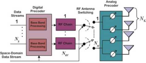
Fig.6. GSM-Aided mmWave massive MIMO Hybrid Beamforming
These selections are called the active antenna groups combination (AAGC) while those unassigned NM - Nrf antenna groups are dormant within this symbol's transmission period. If M ≥ 1 stands for the total number of active group combinations, and one is selected out of M in each symbol period, then based to GSM rule M is given by equation 4
M = 2⌊ юд. ()⌋
Where ⌊ ․ ⌋ represent the floor operation and (.) represent the binomial coefficient.
From section III, we see that we divide the information bits into two parts. While the initial part is used for the transmitted antenna array index, the other part is then used for the modulation symbol which is then transmitted at the active antenna group combination by the chosen analog RF beam. The transmitted signal x is given by equation 5
X=(5)
-
„ _ г 1 _ .p N mX N p4SC ,
Where = [ , fRF,………․․ ] ∈is the weight vectors of the transmitted analog beamforming, while s = [ si ,q, sj ,q,……sj ,q,…․si ,q]
^MscX 1.
-
■L- are the total symbols together with the
modulated symbol of every individual data stream. Each
, represent the modulated symbol sq of the i th data stream been transmitted by the j th active antenna group combination at the BS and i = 1, 2, ….., ^Msc , while j ∈ {1,2,…․․, Nr } where the modulation symbol is a function of the modulation order used i.e. M-QAM etc. The received signal at the small cell for i th data stream with i th RF beam processed by RF receive beamforming weight vector is given by equation 6 [3]
Vi = √ Pi ∑n=l (^RF) HHt , jfRFSn + ( ^RF ) Hnt (6)
Where Pi is the average power received, WRF is the analog received beamforming weight vector.
^kscX . . .
, ∈ ■L. is the channel matrix connecting the jth active antenna group combination at the BS and the ith small cell with ni ∈ :C been independent identically distributed (i.i.d) complex Gaussian variable with (0, σ2).
There are many mmWave MIMO channel models adopted for SM-aided mmWave massive MIMO system, some are 2-D while others are 3-D. The authors in [8] adopted the 3-D statistical wideband model for the mmWave outdoor mobile channel while the authors in [19] adopted the 2-D double-directional time-invariant model. In this work, we adopted the 3-D geometric channel model used by the authors in [3] where the channel matrix , is expressed by equation 7
Hi , j = √ Ms ∑ \u ∝ i , I ar ( ∅ ri , l9i , I ) at ( ∅ I . i , 9* , i ) (7)
Where ∝ , is the complex gain of each multipath and the sum of the complex gain of all multi-paths is one i.e. ∑ ∝ , = 1. Also, (∅ , and , ) are the azimuth and elevation angles of arrival respectively while (∅ . , ) are the azimuth and elevation angles of departure respectively. We also have that ^t (∅ . , ,)
is the BS transmitted array response or steering vector with the corresponding azimuth and elevation departure angles while ar (∅ , , , ) is the small cell received array response steering vector with the corresponding azimuth and elevation arrival angles. Since the uniform planar array (UPA) geometry are used, The array response vector of a UPA in the x - z plan with W element in the z-axis and H element in the x-axis is given by equation 8 [3].
/N
aUPA ( ∅ , e )=
1 -„-If ∆( msin (∅) sin(e) + ncos ( в ))
-
1, v/Lp ,
„--if ∆(( W-l ) sin(∅) sin(e)+( H-l ) (e))
,
] (8)
Where I = √-1 , f = 2 Л ⁄ X with X as the carrier wavelength and the inter-element spacing is ∆.
N = WH with 0 ≤ m ≤ W and 0 ≤ n ≤ H been the z and x indices of an antenna element respectively.
Table 1. AAGC Selection Table
|
Information bits |
AAGC (Any Four) |
Remark |
|
00 |
[1 1 0 0] T |
AAGC 1, 2 Transmit while 3, 4 are Quiet |
|
01 |
[1 0 1 0] T |
AAGC 1, 3 Transmit while 2, 4 are Quiet |
|
10 |
[1 0 0 1] T |
AAGC 1, 4 Transmit while 2, 3 are Quiet |
|
11 |
[0 1 1 0] T |
AAGC 2, 3 Transmit while 1, 4 are Quiet |
-
VII. Gsm-Aided Hybrid Beamforming Scheme
Implementation
We examined our proposed GSMA-HBF scheme implementation in this section. Since the BS and the small cells use GSM for transmission, the same sequence applies for both. Considering the uplink scenario from the small cell to the BS, the choice of ^RF active antennas is selected based on
⌊ log2 ( Nrf ) ⌋
information
bits. (We select the small cell uplink scenario for ease of computation using smaller parameter numbers). Consider the use of minimum RF chain for GSM such that
Nmsc =4 and Nrf =2 , using ⌊ log2(2) ⌋ = ⌊ log26 ⌋ = ⌊ 2.585 ⌋ = 2 information bits where the modulation scheme according to equation (4) is 2 2 = 4 i.e. 4QAM. Also the information bits mapping to the AAGC is derived from the selection of all possible combinations of two antennas groups from four to form an antenna group combination activation pattern of nrfx 1 vector that includes 1's and 0's such that a 1 indicate an active
AAGC and a 0 indicate that the AAGC is silent. For the above scenario, (2) will give us six activation patterns of [1 1 0 0] T ,[1 0 1 0] T ,[1 0 0 1] T ,[0 1 1 0] T ,[0 1 0 1] T , [0 0 1 1] T out of which only 4 are needed for signaling as shown below in Table 1:
The total number of bits transmitted by the small cell GSMA-HBF per channel use is therefore given by equation 9
⌊ log 2( NNrSp ) ⌋ + Nrf ⌊ log 2| M | ⌋ bpcu (9)
Which gives us 6 bpcu for Nmsc =4, Nrf =2, and M = 4-QAM. Since only half of the AAGC is activated per channel use in the GSMA-HBF example above the energy efficiency is improved significantly.
In Table 2 shows the comparison of our proposed scheme with the classical digital beamforming and the hybrid beamforming in terms of the cost and energy usage where DBF gives an implementation cost of about USD59,000 compared with HBF of about USD24,000 and GSMA-HBF with the least cost of about USD6,000. Similarly, GSMA-HBF gives the least energy consumption of about 96W.
Extract from Table 2 is shown in figure 7 and 8. Figure 7 depicts the comparison of the cost of the various beamforming techniques, it shows GSMA-HBF as the most cost-effective scheme which can be used in the 5G cell densification where large numbers of small cell BS are deployed making cost an issue.
Table 2. Comparison of cost and power for DBF, HBF and GSMA-HBF Architecture [30]
|
Devices |
Cost (USD $) |
Power Usage (W) |
Qty in DBF |
Qty in HBF |
Qty in GSMA-HBF |
|
PA |
50 |
3.68 |
64 |
64 |
16 |
|
PA Driver |
30 |
0.85 |
64 |
64 |
16 |
|
LNA |
27 |
0.33 |
64 |
64 |
16 |
|
LO Amp |
30 |
0.6 |
64 |
8 |
2 |
|
Phase Shifter |
170 |
0 |
0 |
64 |
16 |
|
IF Tx Chain |
140 |
1.75 |
64 |
8 |
2 |
|
IF Rx Chain |
140 |
1.25 |
64 |
8 |
2 |
|
DAC |
55 |
2.07 |
64 |
8 |
2 |
|
ADC |
451 |
2.81 |
64 |
8 |
2 |
|
Total Cost |
Total Power |
||||
|
DBF Architecture |
59,072 |
860.16 |
|||
|
HBF Architecture |
24,256 |
385.28 |
|||
|
GSMA-HBF Architecture |
6,064 |
96.32 |
|||
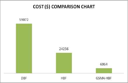
Fig.7. Comparison of the cost of DBF, HBF, and GSMA-HBF in USD
Figure 8 depicts the comparison of the energy of the various considered beamforming techniques showing GSMA-HBF with 96.32W as the most energy efficient scheme to be used in the 5G cell densification where large numbers of small cell BS are deployed making energy consumption an issue.
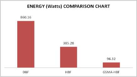
Fig.8. Comparison of the energy consumption of DBF, HBF, and GSMA-HBF in Watts
-
VIII. Conclusion
The generalized spatial modulation aided hybrid beamforming architecture will make the use of small cells affordable for personal indoor applications such as homes, malls, airports etc in the forthcoming 5G where the 5G architecture is suggested to follow the indooroutdoor dichotomy [31]. With the use of mmWave in 5G, GSM-aided hybrid beamforming can also be accommodated in 5G handsets.
References 5G small cell backhaul: a solution based on GSM-aided hybrid beamforming
- B. Marco, D. Renzo, H. Haas, A. Ghrayeb, S. Sugiura, and L. Hanzo, “Spatial Modulation for Generalized MIMO : Challenges , Opportunities , and Implementation,” vol. 102, no. 1, 2014.
- O. B. Idowu-Bismark, A. E. Ibhaze, and A. A. Atayero, “Mimo Optimization Techniques and Their Application in Maximizing Throughput for 3GPP HSPA+,” J. Wirel. Netw. Commun., vol. 7, no. 1, pp. 1–8, 2017.
- Y. Cui, X. Fang, and L. Yan, “Hybrid Spatial Modulation Beamforming for mmWave Railway Communication Systems,” IEEE Trans. Veh. Technol., vol. 65, no. 12, pp. 9597–9606, 2016.
- K. M. Humadi, A. I. Sulyman, and A. Alsanie, “Spatial Modulation Concept for Massive Multiuser MIMO Systems,” vol. 2014, 2014.
- N. Serafimovski et al., “Practical Implementation of Spatial Modulation,” pp. 1–12.
- M. C. Lee and W. H. Chung, “Transmitter design for analog beamforming aided spatial modulation in millimeter wave MIMO systems,” IEEE Int. Symp. Pers. Indoor Mob. Radio Commun. PIMRC, 2016.
- Y. Merve, “Hybrid Beamforming with Spatial Modulation in Multi-user Massive MIMO mmWave Networks.”
- J. Wang, L. He, and J. Song, “An Overview of Spatial Modulation Techniques for Millimeter Wave MIMO Systems,” no. November, pp. 51–56, 2017.
- R. W. H. Jr, N. González-prelcic, S. Rangan, W. Roh, and A. M. Sayeed, “An Overview of Signal Processing Techniques for Millimeter Wave MIMO Systems,” vol. 10, no. 3, pp. 436–453, 2016.
- O. Idowu-Bismark, F. Idachaba, and A. A. A. Atayero, “A Survey on Traffic Evacuation Techniques in Internet of Things Network Environment,” Indian J. Sci. Technol., vol. 10, no. 33, pp. 1–11, 2017.
- O. Idowu-Bismark, F. Idachaba, and A. Atayero, “Massive MIMO Channel Characterization and Modeling: The Present and the Future,” Int. J. Appl. Eng. Res. ISSN, vol. 12, no. 23, pp. 973–4562, 2017.
- L. He, S. Member, J. Wang, S. Member, J. Song, and A. S. Model, “On Massive Spatial Modulation MIMO : Spectral Efficiency Analysis and Optimal System Design,” 2016.
- A. Garcia-rodriguez and C. Masouros, “Low-Complexity Compressive Sensing Detection for Spatial Modulation in Large-Scale Multiple Access Channels,” vol. 63, no. 7, pp. 2565–2579, 2015.
- P. Raviteja, T. L. Narasimhan, and A. Chockalingam, “Detection in Large-Scale Multiuser SM-MIMO Systems : Algorithms and Performance,” 2014.
- N. Serafimovski, S. Sinanovi, M. Di Renzo, and H. Haas, “Multiple access spatial modulation,” pp. 1–20, 2012.
- L. He, S. Member, J. Wang, and S. Member, “Bandwidth Efficiency Maximization for Single-Cell Massive Spatial Modulation MIMO : An Adaptive Power Allocation Perspective,” vol. 5, 2017.
- T. L. Narasimhan, P. Raviteja, and A. Chockalingam, “Large-Scale Multiuser SM-MIMO Versus Massive MIMO.”
- O. Idowu-bismark, F. Idachaba, and A. A. A. Atayero, “A Survey on Traffic Evacuation Techniques in Internet of Things Network Environment,” vol. 10, no. September, 2017.
- C. Sacchi, T. F. Rahman, I. A. Hemadeh, and M. El-Hajjar, “Millimeter-Wave Transmission for Small-Cell Backhaul in Dense Urban Environment: A Solution Based on MIMO-OFDM and Space-Time Shift Keying (STSK),” IEEE Access, vol. 5, pp. 4000–4017, 2017.
- Z. Gao, L. Dai, D. Mi, Z. Wang, M. A. Imran, and M. Z. Shakir, “MmWave massive-MIMO-based wireless backhaul for the 5G ultra-dense network,” IEEE Wirel. Commun., 2015.
- X. Ge, S. Tu, G. Mao, C. X. Wang, and T. Han, “5G Ultra-Dense Cellular Networks,” IEEE Wirel. Commun., vol. 23, no. 1, pp. 72–79, 2016.
- M. A. Rt, “S M A RT B A C K H A U L I N G A N D F R O N T H A U L I N G F O R 5G N E T W O R K S B ACKHAULING 5G S MALL C ELLS : A R ADIO R ESOURCE M ANAGEMENT P ERSPECTIVE,” no. October, pp. 41–49, 2015.
- O. Idowu-bismark, O. Kennedy, F. Idachaba, and A. A. Atayero, “A Primer on MIMO Detection Algorithms for 5G Communication Network,” vol. 8, no. June, pp. 194–205, 2018.
- E. Basar and S. Member, “Index Modulation Techniques for 5G Wireless Networks,” no. 114, pp. 1–14, 2016.
- N. Serafimovski and H. Haas, “Generalised spatial modulation,” no. December, 2010.
- T. L. Narasimhan, P. Raviteja, and A. Chockalingam, “Generalized Spatial Modulation in Large-Scale Multiuser MIMO Systems,” pp. 1–15.
- R. Mesleh and A. Younis, “LOS millimeter-wave communication with quadrature spatial modulation,” 2016 IEEE Int. Symp. Signal Process. Inf. Technol. ISSPIT 2016, no. December, pp. 109–113, 2017.
- P. Liu and A. Springer, “Space Shift Keying for LOS Communication at mmWave Frequencies,” IEEE Wirel. Commun. Lett., vol. 4, no. 2, pp. 121–124, 2015.
- A. R. G. S. M. Transmitter, “Generalized-Spatial-Modulation-Based Reduced-RF-Chain Millimeter-Wave Communications,” 2016.
- B. Yang, Z. Yu, J. Lan, R. Zhang, J. Zhou, and W. Hong, “Digital Beamforming-Based Massive MIMO Transceiver for 5G Millimeter-Wave,” IEEE Trans. Microw. Theory Tech., vol. 66, no. 7, pp. 3403–3418, 2018.
- O. Idowu-bismark, O. Kennedy, R. Husbands, and M. Adedokun, “5G Wireless Communication Network Architecture and Its Key Enabling Technologies,” vol. 12, no. April, pp. 70–82, 2019.
- N. Serafimovski and H. Haas, “Generalised spatial modulation,” no. December, 2010.
- T. L. Narasimhan, P. Raviteja, and A. Chockalingam, “Generalized Spatial Modulation in Large-Scale Multiuser MIMO Systems,” pp. 1–15.
- O. E. Agboje, O. B. Idowu-Bismark, and A. E. Ibhaze, “Comparative analysis of fast fourier transform and discrete wavelet transform based MIMO-OFDM,” Int. J. Commun. Antenna Propag., vol. 7, no. 2, 2017.
