A 3-Level Secure Histogram Based Image Steganography Technique

Author: G V Chaitanya, D Vamsee Krishna, L Anjaneyulu
Journal: International Journal of Image, Graphics and Signal Processing(IJIGSP) @ijigsp
Article in issue: 4 vol.5, 2013.
Free access
Steganography is an art that involves communication of secret data in an appropriate carrier, eg. images, audio, video, etc. with a goal to hide the very existence of embedded data so as not to arouse an eavesdropper's suspicion. In this paper, a steganographic technique with high level of security and having a data hiding capacity close to 20% of cover image data has been developed. An adaptive and matched bit replacement method is used based on the sensitivity of Human Visual System (HVS) at different intensities. The proposed algorithm ensures that the generated stego image has a PSNR greater than 38.5 and is also resistant to visual attack. A three level security is infused into the algorithm which makes data retrieval from the stego image possible only in case of having all the right keys.
Steganography, Matched Bit-Replacement, Visual Attack
Short address: https://sciup.org/15012701
IDR: 15012701
Text of the scientific article A 3-Level Secure Histogram Based Image Steganography Technique
The modern formulation of Steganography[1]-[3] is often given in terms of the prisoner’s problem proposed by Simmons[4]-[5], where two inmates wish to communicate in secret to hatch an escape plan. All of their communication passes through a warden who will throw them in solitary confinement should she suspect any covert communication. Hence, the problem statement is to send a message from one point to another through a harmless cover message, which cannot arouse any suspicion in the intermediary stages. Generic steganography process is shown in Fig 1. In digital image steganography, the secret message is embedded within digital image called cover-image. Cover-image carrying embedded secret data is referred as stego-image. Steganography can be used for wide range of applications such as, in defence organisations for safe circulation of secret
Data, in medical imaging, patient’s details are embedded within image providing protection of information and reducing transmission time and cost [6], to make the online election secure and robust against a variety of fraudulent behaviours [7], for data hiding in countries where cryptography is prohibited, in improving mobile banking security [8] etc. The advantage of Steganography over cryptography alone is that messages do not attract attention to themselves.
Plainly visible encrypted messages no matter how unbreakable, will make it clear that there is some secret data and might result in the message being destroyed totally by the warden.
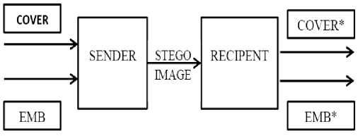
Fig.1. A cover image embedded with data is called stego image which is transmitted by the sender. The recipient retrieves the embedded data
EMB with a key already shared, here EMB* =EMB. The COVER* image need not be same as the original cover image COVER.
Steganographic techniques have various features which characterize their strengths and weaknesses. Features include the following:
Embedding capacity: It refers to the amount of data that can be inserted into the cover-media without deteriorating its integrity.
Perceptual transparency: It is necessary that to avoid suspicion the embedding should occur without significant degradation or loss of perceptual quality of the cover media.
Computational complexity: It refers to how complex or time consuming is the steganographic technique employed for encoding and decoding data should also be given importance.
Robustness : It refers to the ability of embedded data to remain intact if the stego-image undergoes various transformations such as scaling, rotation, cropping or compression.
Younes, et al. [9] proposed a method in which message is embedded into LSB of each pixel within the cover-image in encrypted form. Mandal [10] proposed a method with minimum deviation of image fidelity resulting high quality stego-image with better embedding capacity. Hadhoud, et al. [11] proposed a technique based on entropy calculation. In this method, the entropy of the higher significant bits is calculated and data is embedded according to the entropy. Bit plane complexity segmentation Steganography (BPCS) was introduced by Kawaguchi, et al. [12] it is based on the simple idea that the higher bit planes can also be used for embedding information.
Though there are several methods developed so far, it is not possible to maximally satisfy all the steganographic requirements simultaneously in a single method. Therefore, the balance of them must be dictated by the application.
To the best of our knowledge, this is the first work to show high data hiding capacity by embedding data adaptively- based on the sensitivity of HVS, following macro block truncation principle. Besides having high data hiding capacity, it provides a three level security by using a Pseudo Random Number Genarator (PRNG) and offers a high resistance to visual Steganalytic attack. This is achieved by totally randomizing the LSB plane thereby removing all traces of visible patterns. Also, the improvement in data hiding capacity by histogram equalization of the cover image has been explored. All this has been achieved by maintaining the PSNR well above 38.5 and without any degradation in perceptual transparency.
The remainder of the paper is organized as below. Section II briefs about the background work, which is the underlying basis of the algorithm. Section III discusses the embedding and retrieval algorithms and its extension to color images. Section IV explores the idea of histogram equalization of cover images as a preprocessing method. Section V explains how the proposed algorithm is resistant to visual attack. And the final section presents the results with appropriate conclusions.
-
II. Background Work
In conventional LSB Steganography, the data is embedded into the LSB Plane of the cover image. In any image, the pixel value is largely determined by the MSB and the significance of the bits gradually decreases down. The data in Bit plane 0 is almost noise and has not much influence on the visible parameters of the image. This property is exploited and the data to be hidden is embedded into the LSB positions, i.e., the least significant bits are replaced by the message data [13-15]. This is illustrated in fig. 2 [16].
The ideal PSNR between the stego and cover image is considered to be in the range of 35-50dB. By assuming average pixel difference to be 3, the PSNR obtained from (1) is 38.5dB which is fairly allowable PSNR for steganographed images. This is illustrated in Figure 3. Here peak to peak value =255. MSE is the mean square error given by (2). C(i, j) and S(i, j) are the pixel intensity values of cover and stego images respectively. M and N are the dimensions of the images.
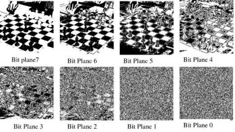
Fig. 2 Data contained in separate bit planes
PSNR = 101og10
(peak to peak value of original data )2
MSE
M-lN-l
MSE=^'E/Z'Ct№"Sl№V‘ k=o f=o (2)
From the above analysis it implies that on an average, the last two bits in every pixel can be changed or replaced with the message data. And, assuming the change in pixel value due to replacement by the message bits to be maximum in all cases (which is a difference of 3), gives a PSNR of 38.5dB which is sufficiently good. But such a situation is fairly unlikely where the message leads to maximum deviation in every pixel and hence the PSNR is always better in practical cases.
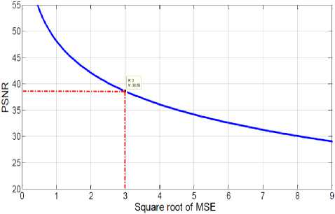
Fig.3. Plot of square root of MSE vs PSNR. For PSNR >35,VMSE should be less than 4.5.
Instead of replacing last two bits in every pixel, the number of bits to be changed in a pixel can be determined adaptively by maintaining the overall total pixel differences within the required PSNR limits. The criterion for determining the number of pixels to be changed is the perceptibility in change of gray scale values by the Human Visual System (HVS) in different gray scale regions [17].
According to the luminance property of HVS, the greater the grayscale value, the lesser is the perceptibility in the change of the grayscale value, as the capability of the HVS to distinguish between closer gray levels reduces at higher intensities. i.e. the lower the intensity value, the better we can distinguish the change in gray levels and as the intensity of pixels increases, the discretion between the gray scale levels decreases. Based on this property, we replace higher number of bits in pixels with higher intensity values and lower number of bits in pixels with lower intensity values.
But the computation involved in carrying out such an operation on a pixel to pixel basis would be high and would also lead to complexities in data retrieval. Hence, to avoid this, the fundamental unit is taken as 8×8 macro block of pixels and the number of bits that are replaced with message data in any pixel of a particular block is determined by the mean intensity of the total pixels inside the block.
In any given image, the pixel intensity values fall in the same range for a small localized region. This ensures that the value of any pixel inside an 8×8 block lies close enough to the mean of the macro block without large variances. Thus, using the macro block as the fundamental unit should produce similar results as that of using a single pixel along with an enhancement in computational ease and fidelity in retrieved data.
-
III. ALGORITHM
-
A. Embedding Algorithm:
Step 1: The cover image in which the message needs to be embedded is truncated into macroblocks of size 8×8.
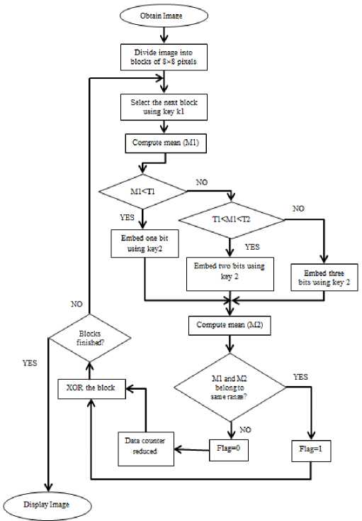
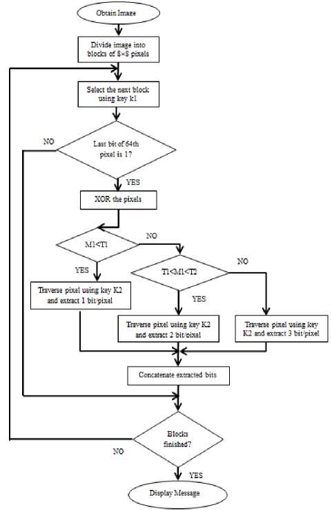
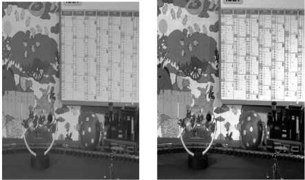
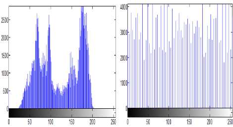
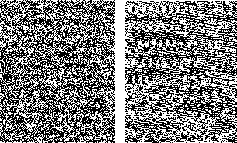
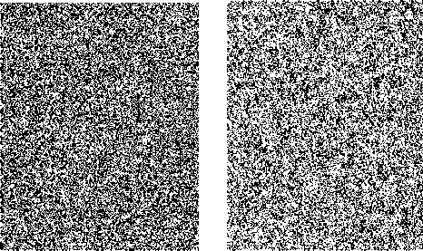
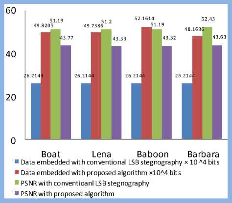
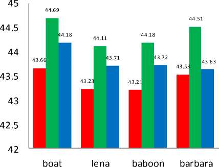
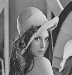
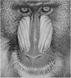
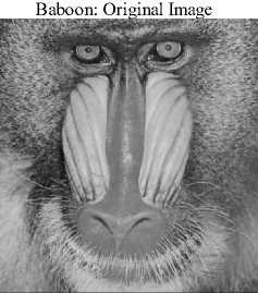
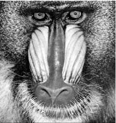
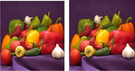
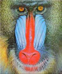
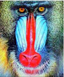
Step 2: The threshold limits T1, T2 are set such that the intensity scale is divided into three region ns satisfying the condition, 0 Step 3: After the image has been divided into blocks, the total number of such macroblocks is computed as ‘n’. A pseudo random number generator (PRNG) is used to generate a random sequence of numbers between 1 to n using a specified key K1. This sequence determines the order of traversal of the image blocks for embedding the data. Each block is picked up according to the random sequence. Step 4: Once the block has been picked according to the sequence, the mean of the intensity of the all pixels in the block is computed. Mean is given as Н = — X°=iZf=i f(L j) (3) Here f(i,j) is the pixel intensity value. Step 5: The mean of the pixel values in the block, µ determines the number of bits to be embedded in each pixel of the block. If µ ϵ [0,T1] replace only 1 bit in each pixel of the block as the sensitivity is high in this region. If µ ϵ (T1,T2] replace 2 bits in each pixel of the block as the sensitivity is relatively lower in this region. If µ ϵ (T2,255] replace 3 bits in each pixel of the block as the sensitivity is lowest in this region as compared to the other two ranges. Step 6: The embedding of message bits in the pixels of each macroblock is not done in a sequential manner. Another key K2 is used to generate a random sequence of numbers from 1 to 63 using a PRNG. This sequence is used to determine the order of embedding the message bits in the pixels of the selected macroblock. The last pixel, i.e. the 64th pixel in the block is not embedded with any data. The number of bits to be replaced in the pixels of the block is determined by the mean intensity of the block, as specified in Step 5. Step 7: LSB Match Adaptation [3] This method calculates the distance between the original intensity and the steganographic pixel intensity. Then we try to minimize this distance by toggling the bits in higher planes without affecting the bits containing the message data. If the new distance is less than the original distance, the pixel value is replaced by this matched value, implying a further reduction in the distortion caused by the hidden information. For example, using a cover byte 11001000 to hide 3 bits of information (111), results in 11001111, this has a difference of 7 with respect to the original. Applying the matched adaptation, in this case the 4th least significant bit is toggled which results in 11000111, with a distance of 1 from the original byte but with the same hidden information. This reduces the distortion produced by the hidden information. Let the intensity value of cover pixel before embedding of message bits be ‘a’ and the intensity value of stego pixel after embedding message bits be ‘b’. As the recipient of the stego image is concerned only with the last 3 bits (which contain the message data), this toggling of 4th bit does not affect the hidden information and at the same time reduces the distortion produced by the hidden information. If the number of bits replaced in a pixel is ‘i’, the ‘i+1’th bit from right is toggled, and the new intensity value is denoted as ‘c’. To obtain a final pixel value closest to the original pixel value, Compute min (|a – b|, |a – c|) If |a – b| > |a – c| then Store ‘c’ as the intensity value of the particular pixel Else Store ‘b’ as the intensity value of the particular pixel This ensures that the distortion produced by the message data is reduced to a minimum and facilitates the mean of the block to lie well within the initial range itself. Step 8: Once the message bits have been embedded into the pixels of the block, the mean of the block is computed again and is denoted as µ’. As the intensity values of the pixels change with the embedding of the message bits, the mean of the block also changes. There is a possibility that with this change in mean, the new mean may fall into another region where different number of bits per pixel are embedded. This would lead to errors in recovery of data from the stego image that is received at the second party. In order to avoid this, the new mean after embedding µ’ is computed. If the new mean still lies in the same region as the mean of the block before embedding the data, the LSB of the 64th pixel in the block (in which no data has been embedded earlier), is taken as the flag bit and is set to ‘1’.In case the mean falls in the other threshold regions, differing from the original mean before data embedding, the flag bit is set to ‘0’ indicating that no data is to be extracted from this block during message retrieval. As this block would be discarded during data retrieval, all the data that’s been embedded in this block is put in the next blocks in order to avoid loss of data. Step 9: In order to remove all kinds of patterns that might be introduced in the lowest bit plane due to embedding of data, and which might give away suspicions about the presence of information in the image, the following method is implemented. The procedure is based on the fact that XOR bit operator is both associative and commutative as shown in equation 4. c = a ⊕ b a = c ⊕ b i.e. when a bit is XORed twice with another bit, it results in the original bit again. This is also true with XNOR. Fig.4. XOR operations performed on LSB The lowest bit plane of the truncated block is taken as an 8×8 matrix of 1s and 0s.The matrix is subjected to a series of folds, where, in each fold, one half of the folded matrix is replaced by the resultant of performing XOR of one half with the other. The folding is continued recursively till we are left with one bit, of the 64th pixel. Fig. 4 illustrates these operations. The white and black blocks are the halves of the matrix which are XORed and the blocks with an ‘x’ in them indicate the original data being replaced by the resultant XOR value. The sequence of folds is stored as a series of 1s and 0s, where a ‘1’ denotes a vertical fold and a ‘0’ denotes a horizontal fold. This series is very important as the same series, but in the reverse order needs to followed during the extraction of data. The number of combinations is limited by the fact that there need to be three ‘1’s and three ‘0’s, i.e. three vertical folds and three horizontal folds. This results in a total of 20 possible permutations (6! / (3!×3!)). The data can be retrieved back without errors only if this sequence is also known exactly, adding a further level of security to the information hidden. As the 64th pixel is unaffected in these operations, the flag data is stored in the LSB of the 64th pixel which denotes the fidelity of the data in the macro block, is safe and unchanged. This results in total randomization of the lowest bit plane and removes all kinds of patterns that might hint about the presence of data. The whole of the embedding algorithm is shown in fig. 5a. Fig. 5a . Data embedding Algorithm Image segmentation refers to partitioning of an image into different regions that are homogeneous or “similar” in some image characteristics. It is usually the first task of any image analysis process module and thus, subsequent tasks rely strongly on the quality of segmentation[1]. In recent years, automatic image segmentation has become a prominent objective in image analysis and computer vision. Various techniques have been proposed in the literature where color, edges, and texture were used as properties for segmentation. Using these properties, images can be analyzed for use in several applications including video surveillance, image retrieval, medical imaging analysis, and object classification. On the outset, segmentation algorithms were implemented using grayscale information only (see [2] for a comprehensive survey). The advancement in color technology facilitated the achievement of meaningful segmentation of images as described in [3, 4]. The use of color information can significantly improve discrimination and recognition capability over gray-level methods. B. Retrieval Algorithm: Step 1: The received stego image is first split into blocks of size 8*8. Step 2: After the image has been divided into blocks, the total number of such blocks are computed, denoted by ‘n’. A PRNG is used to generate a random sequence of numbers between 1 to n using the received key K1. This sequence determines the order of traversal of the image blocks for retrieving the data. Step 3: Once the block has been picked according to the sequence, the LSB of the 64th pixel is checked. This bit is the flag bit which determines whether data needs to be retrieved from the block or not. If the flag bit is ‘0’, it denotes that the mean of the block has changed after the embedding of the data and would result in errors during retrieval. Hence, this block is discarded and we move on to the next block. If the flag bit is ‘1’, data can be retrieved from the block. Before retrieval, the LSB plane of the block is taken as an 8×8 matrix and the following operation is performed: Starting off from the last bit, i.e. the 64th bit, the matrix is unfolded according to the series sent along with the stego image which determines the sequence of vertical and horizontal unfolding. Each half of the matrix is XORed with the other half and the resultant data is replaced in the half of the matrix. This is done till the entire matrix is unfolded. The XOR operation needs to be performed in an exactly opposite fashion to which it has been performed while encoding. The order of ‘1’s and ‘0’s obtained from the sender is used to do this operation. Fig. 5b. Data retrieval Algorithm If µ ϵ (T1,T2] then retrieve 2 bits from each pixel of the block. If µ ϵ (T2,255] then retrieve 3 bits from each pixel of the block. The bits are retrieved from the pixels not in a sequential manner, but in the sequence determined by the received key K2, which generates a sequence of numbers from 1 to 63using a second PRNG. Step 5: The data bits thus obtained from all the blocks are concatenated and are reconstructed back into the respective format which can be text, image, etc. The entire retrieval algorithm is shown as a flow chart in fig. 5b. C. Extension to Color Images The above algorithm can be extended to color images by simply breaking down the image into 3 color channels – red, green and blue respectively. The same operations are performed on each color plane and the resultant planes after embedding the data are concatenated together to form back the final stego image with the hidden data. For retrieving the data, the stego image is broken down into respective color planes, and data is extracted from each plane by using the decoding algorithm. In case of color images, as each pixel has 3 components, R G and B, the data that can be hidden is increased up to three times when compared to grayscale images. IV. HISTOGRAM EQUALIZATION The threshold levels are determined on the basis that as intensity increases the perceptibility of difference in intensity levels of a pixel by the HVS decreases. Thus, one method of determining the levels T1 and T2 is to divide the intensity scale into three equal halves in ascending order such that 0< T1 < T2 < 255. But for most of the images take for example fig. 6a, the histogram is not really uniform on the intensity scale. Rather, the pixels are generally concentrated in one particular intensity region as shown in fig. 7a. This limits the data that can be embedded in the image. For example, in the sample caltrain image considered in fig. 6a has large number of pixels falling in the region of intensity levels between 50-100 and 150-200, with T1 as 85 and T2 as 170, it leads to most of the pixels lying only in the first and second regions, which limits the possibility of three bits being embedded in a pixel considerably. Hence, as a solution to get the distribution of data uniformly is histogram equalization [9]. This can be performed on the image as a preprocessing step before determining the threshold levels and then embedding the data. This method usually increases the global contrast of most images, especially when the usable data of the image is represented by close contrast values. Through this adjustment, the intensities can be better distributed on the histogram. This allows for areas of lower local contrast to gain a higher contrast as shown in fig. 6b. The histogram equalization ensures nearly same number of pixels in almost all the intensity regions on a grey scale as it is evident from fig. 7b. There is a possibility that histogram equalization can produce undesirable effects (like visible image gradient) when applied to images with low intensity depth. Hence, only those images which get enhanced after histogram equalization need to be preferred. Fig.6. (a) Original Image (b). Histogram equalized image After the image has been equalized, the threshold levels can be determined as discussed earlier such that the intensity scale is divided into three equal parts in a way that there are approximately equal number of pixels in each region. i.e. T1=85, T2=170. Fig.7. (a). Histogram of caltrain image (b). Equalized histogram Histogram equalization preprocessing leads to an increase in data hiding capacity as there will be a fair number of pixels in the higher intensity region which can store up to 3 bits of information per pixel. Data of 386821 bits with PSNR of 43.24 dB was embedded into caltrain cover image. And when histogram preprocessing was done 406981 bits at PSNR of 42.83 dB was obtained. The number of bits that can be embedded has increased by an impressive 21Kb in this case. These results were for a cover image with dimensions 400×512. Similar analysis on various other standard images is discussed in detail in section VI. V. RESISTANCE TO VISUAL ATTACK The most common attack on Steganographed images that are based on bit replacement in the spatial domain is the visual attack [18]. In this, every pixel of the stego image with the secret data is first read and the LSB is extracted. If the LSB is 1, the pixel intensity value is set to maximum, i.e. 255 or total white. If the LSB value is 0, the pixel intensity value is set to minimum, i.e. 0 or total black. After this operation, the image is reconstructed back with the new pixel values, which simply are either black or white. An ordinary image without any hidden data, when subjected to this process would generate a totally random image which can be seen in fig. 8a as the LSB would just be a random distribution of ‘1’s and ‘0’s. Fig.8. (a) LSB plane of normal image (b) LSB plane of image with text embedded In case of images containing secret data, this leads to the generation of patterns which can be seen in fig. 8b which make it quite evident that information is hidden in the LSB plane. The occurrence of patterns is attributed to the fact that the ASCII values of most of the characters and text are close together leading to the same bit values in the higher bits. This leads to the formation of patterns in the LSB plane which is contrary to the otherwise random values in the least bit of the image pixels. The two keys introduced in the algorithm, besides providing security and avoiding unauthorized data retrieval, also randomize the LSB plane sufficiently enough to prevent any kind of patterns that might be detected by visual attack test. After the key K1 is introduced to randomize the selection of blocks for data embedding, the extent of patterns has considerably reduced but not totally eliminated. Fig. 9a shows that the designs are still present though not very evident. а№?'Ш1 е'й" Sj аЧс'й OY £ YKliicE ПА%' EQ I u],Mr^i5mS0!?"^^ i{ c ~ 8Zne: uf£. i Ша {)нВ12ЫаКГ5Н31ЛМ0П(ЖЖ ltDj AsY 8 fO- se9;ut u }z g(? b • :'T^3016-«kaV TI ; *Sfflk[a Tu 131'рА1Ч; ш ;rx8(0 50 ± ZRi° 6>Su3y} P B 'iJn[ 701 < ^LAifYOUx Tg т E:Bi Zq/B",с _ a cM +АкёВ1\с?_(ОА i ,й» ё §‘ бВЭВЬг]1 c:3 try e:Bbrjt ОТ 0 3g < ii< / шивмтшвикиншзтшг ?3ё V й5=Йа1аю6Й # e 1 S'» g'i'iN 3№ a0 a/ЁА SiSO Fig.9. (a) LSB plane of stego image (b) Appearance of text patterns with one key Also, another disadvantage in using only a single key is that, though the selection order of blocks has been randomized, the data embedding inside the pixels of the block is still done in a conventional sequential manner. This is the reason for the traces of patterns being visible. In this case, even if the attacker does not have the correct key, the decoded data might not be totally random because of the sequential order followed inside the 8×8 macro blocks leading to the appearance of small letters and text of up to 8 characters (minimum data that would be present in 63 pixels), as shown in Fig. 9b. The introduction and usage of two random sequences for traversal of blocks as well as another for traversal of pixels inside a macro block, will totally remove the designs along with providing a two level security. The XOR operation further removes all sorts of redundancies and symmetric data in the LSB plane, and almost resembles the LSB plane of the original image. Fig. 10a and 10b illustrates this. Fig.10. (a). LSB plane of stego image (b). LSB plane after with two keys XOR operations All of the aforementioned operations were carried out on the cover image Lena with dimensions of 512×512. VI. RESULTS AND CONCLUSIONS A. Experimental Results To assess the efficacy and efficiency of the proposed algorithm simulations were performed on four standard gray scale cover images of 512 × 512 dimensions as shown in fig. 11. All the Stego images which were obtained with and without preprocessing had good perceptual transparency. The cover images when preprocessed with histogram equalization have shown improved contrast levels and image quality. These processed images were used as cover images and the resultant stego images are shown in the third row of fig. 13. A comparative analysis is carried out between conventional LSB steganography with the proposed algorithm. The data hiding capacity has almost doubled. Though the PSNR has decreased it is ensured that is does not fall below 38.5 as explained in section II. It is to be noted that this analysis is carried out for cover images when no histogram equalization was done. This is illustrated fig. 11. From Table 1 it can be inferred that around 24% of cover image data has been replaced with secret data to be embedded. The PSNR values are also satisfactory and are as expected. With histogram preprocessing the embedding capacity has increased impressively. Except for Baboon which showed a nominal decrease in data hiding capacity due to the fact that its global average intensity (average intensity value of all pixels) value falls predominantly in second and third intervals as described in section IV. Fig. 11. Comparative analysis with conventional LSB steganography and the proposed algorithm without preprocessing. In such circumstances the preprocessing might find little use. Never the less the proposed algorithm without preprocessing also embeds close to 2bits/pixel. Boat 520255 43.18 24.80 21.53 Lena 512821 43.03 24.45 15.07 Baboon 516097 43.31 24.60 -5.51 Barbara 520759 42.97 24.83 38.21 ■ PSN R without LSB Matching ■ PSN R with LS B Matching ■ PSN R with LS B Matching a nd afte r XOR operation Table 1 Analysis when cover image is preprocessed Cover Image Data Embedded PSNR Percent of cover image data replaced Increase in embedding capacity in Kb Fig.12. PSNR analysis at various stages of proposed algorithm with histogram equalization preprocessing. Boat: Original Image Lena : Original Image Baboon: Original Image Barbara: Original Image Boat: Stego Image Lena: Stego Image Baboon: Stego Image Barbara: Stego Image Boat: Stego Image with histogram pre-processing Lena: Stego Image with histogram pre-processing Baboon: Stego Image with histogram pre-processing Barbara: Stego Image with histogram pre-processing Fig.13. Simulations performed on various standard cover images using the proposed algorithm To understand the effect of bit matching and adding additional security levels (key 2 for LSB randomization inside the macro block and XOR operation) on the quality of image a PSNR analysis was carried out after every stage. From fig. 12 it is clear that after XOR operation PSNR did not vary much and image maintained good perceptual transparency. At the cost of this very nominal decrement in PSNR made the image robust against visual attacks and added two new security levels. The proposed algorithm was also implemented on color images with the premise of the algorithm extension as described in section III C. The images obtained before and after data embedding can be seen in fig. 13a and 13b. Fig.13. (a) Peppers:Original Image. (b) Setgo image without preprocessing Any preprocessing for color image is a complex process as it involves three color planes and any degradation in one of the planes results in global distortion of the image quality. Hence as stated earlier preprocessing is advised only in cases where there is an improvement in image quality and also data hiding capacity. Table 2 Data embedding capacity of color image peppers (dimensions 384×512) Color Plane Data embedded PSNR Percent of cover image data replaced Red 343477 43.15 21.84 Green 255592 47.13 16.25 Blue 220627 48.99 14.03 Total 819696 bits 17.37 Fig.14. (a) baboon: Cover Image (b) Stego image with preprocessing The proposed algorithm along with preprocessing is implemented on Baboon color image. This is illustrated in fig. 14a and 14b. A global increment close to 5Kb of additional data was embedded when preprocessing was done. The PSNR values were also satisfactory and are well above the estimated 38.5 which is for the worst case scenario. These are illustrated in Table 3. Without preprocessing Histogram Equalized Color plane Data Embedded PSNR Data Embedded PSNR Red 540100 42.49 504631 43.32 green 518176 43.14 514018 43.21 blue 463429 43.77 508978 43.32 Total 1521705 bits 1527627 bits B. Conclusion A new 3-level secure, histogram based steganography technique has been developed. The proposed algorithm has high data embedding capacity around 20% of cover image data, yet maintaining a high PSNR value and good perceptual transparency. An adaptive and matched bit replacement method is used based on the premise of sensitivity of HVS at different intensities. The proposed algorithm is robust against visual attack as three levels of security have been interspersed. A histogram equalization preprocessing technique was explored which gave impressive improvements in data embedding capacity specifically for gray scale images, though this has to be used only in cases were the cover image does not degrade after equalization. The proposed algorithm can be extended to color images and this has shown satisfactory results.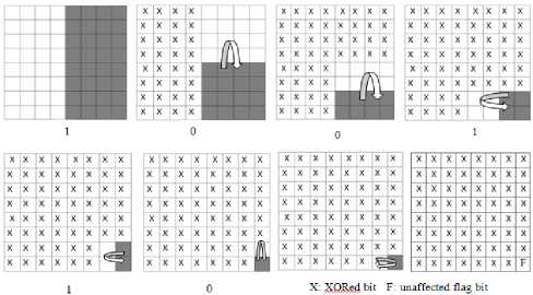


References A 3-Level Secure Histogram Based Image Steganography Technique
- Petitcolas, F.A.P., Anderson, R.J., and Kuhn, M.G. "Information hiding – a survey", Proc. IEEE, 1999, 87,(7), pp. 1062–1078
- T. Morkel , J.H.P. Eloff, M.S. Olivier. "An Overview Of Image Steganography". Information and Computer Security Architecture (ICSA) Research Group Department of Computer Science University of Pretoria, 0002, Pretoria, South Africa.
- Babloo Saha and Shuchi Sharma, "Steganographic Techniques of Data Hiding using Digital Images". Defence Science Journal, Vol. 62, No. 1, January 2012, pp. 11-18.
- Gustavus J. Simmons. "The Prisoners Problem and the Subliminal Channel. In Advances in Cryptology" – CRYPTO '83, pages 51–67, New York, 1984. Lecture Notes in Computer Science, ed. D. Chaum.
- Chandramouli, R., Kharrazi, M. &Memon, N., "Image steganography and steganalysis: Concepts and Practice", Proceedings of the 2nd International Workshop on Digital Watermarking, October 2003
- H. Sencar, M. Ramkumar, and A. Akansu, "Data Hiding Fundamentals and Applications: Content Security in Digital Multimedia". Elsevier:Academic, 2004.
- Katiyar, S.; Meka, K.R.; Barbhuiya, F.A. & Nandi, S. Online voting system powered by biometric security using steganography. In the 2nd International Conference on Emerging Applications of Information Technology (EAIT), Kolkata, India, 2011, pp. 288-291.
- Shirali-Shahreza, M. Improving mobile banking security using steganography. In the 4th International Conference on Information Technology, ITNG, Las Vegas, 2007, pp 885-887.
- Younes, Mohammad Ali Bani&Jantan, A. "A new steganography approach for image encryption exchange by using the least significant bit insertion". Inter. J. Comp.Sci. Network Security, 2008, 8(6), 247-254.
- Mandal, J.K. &Sengupta, M. "Steganographic technique based on minimum deviation of fidelity (STMDF)". 2nd International Conference on Emerging Applications of Information Technology (EAIT), Kolkata, 2011, pp. 298-301.
- Hadhoud, M.M.; Ismail, N.A.; Shawkey, W. &Mohammed, A.Z." Secure perceptual data hiding techniqueusing information theory." In the International Conference on Electrical, Electronic and Computer Engineering(ICEEC), Egypt, 2004, pp. 249-253.
- Kawaguchi, E. & Eason, R.O." Principle and applicationsof BPCS-Steganography. In the SPIE Conference on Multimedia Systems and Applications", Boston, 1998,3524, pp. 464-73.
- Analysis of LSB based Steganography Techniques, R.Chandramouli, NasirMemon, IEEE 2001.
- Dr. EktaWalia, Payal Jain, Navdeep. "An Analysis of LSB & DCT based Steganography" Global Journal of Computer Science and Technology, April 2010.
- Yeuan-Kuen Lee and Ling-Hwei Chen, "An Adaptive Image Steganographic Model Based on Minimum-Error LSB Replacement", Department of Computer and Information Science National Chiao Tung University, Hsinchu.
- Digital Image Processing, 2nd Edition. Rafael E. Gonzalez, Richard E. Woods.
- An Adaptive Image Steganographic Model Based on Minimum-Error LSB Replacement Yeuan-Kuen Lee and Ling-Hwei Chen, Department of Computer and Information Science National Chiao Tung University, Hsinchu.
- Attacks on Steganographic Systems. Breaking the Steganographic Utilities EzStego, Jsteg, Steganos, and S-Tools-and Some Lessons Learned.
