A Design High Impact Lyapunov Fuzzy PD-Plus-Gravity Controller with Application to Rigid Manipulator

Author: Farzin Piltan, Mohammad Javad Rafaati, Fatima Khazaeni, Ali Hosainpour, Samira Soltani
Journal: International Journal of Information Engineering and Electronic Business(IJIEEB) @ijieeb
Article in issue: 1 vol.5, 2013.
Free access
The control problem for manipulators is to determine the joint inputs required to case the end-effector execute the commanded motion. The nonminimum phase characteristic of a rigid manipulator makes the design of stable controller that ensure stringent tracking requirements a highly nontrivial and challenging problem. A useful controller in the computed torque family is the PD-plus-gravity controller. Methodology. To compensate the dynamic parameters, fuzzy logic methodology is used and applied parallel to this method. when the arm is at rest, the only nonzero terms in the dynamic is the gravity. Proposed method can cancels the effects of the terms of gravity. In this case inorder to decrease the error and satteling time, higher gain controller is design and applied to nonlinear system.
Computed torque controller, PD plus gravity, fuzzy logic theory, fuzzy PD plus gravity method
Short address: https://sciup.org/15013161
IDR: 15013161
Text of the scientific article A Design High Impact Lyapunov Fuzzy PD-Plus-Gravity Controller with Application to Rigid Manipulator
Published Online May 2013 in MECS
Robot manipulators have many applications in aerospace, manufacturing, automotive, medicine and other industries. Robot manipulators consist of three main parts: mechanical, electrical, and control. In the mechanical point of view, robot manipulators are collection of serial or parallel links which have connected by revolute and/or prismatic joints between base and endeffector frame. The robot manipulators electrical parts are used to run the controllers, actuators for links motion and sensors, which including the following subparts: power supply to supply the electrical and control parts, power amplifier to amplify the signal and driving the actuators, DC/stepper/servo motors or hydraulic/pneumatic cylinders to move the links, and transmission part to transfer data between robot manipulator subparts [1-3]. Control part is used to adjust the timing between the subparts of robot manipulator to reach the best trajectory. It provides four main abilities in robot manipulators [2-4]: controlling the manipulators movement in correct workspace, sensing the information from the environment, being able to intelligent control behavior and processing the data and information between all subparts.
Automatic control has played an important role in advance science and engineering and its extreme importance in many industrial applications, i.e., aerospace, mechanical engineering and robotic systems. The first significant work in automatic control was James Watt’s centrifugal governor for the speed control in motor engine in eighteenth century[5-7]. There are several methods for controlling a robot manipulator, which all of them follow two common goals, namely, hardware/software implementation and acceptable performance. However, the mechanical design of robot manipulator is very important to select the best controller but in general two types schemes can be presented, namely, a joint space control schemes and an operation space control schemes[1]. Joint space and operational space control are closed loop controllers which they have been used to provide robustness and rejection of disturbance effect. The main target in joint space controller is design a feedback controller that allows the actual motion ( qa(t) ) tracking of the desired motion ( q
Some of robot manipulators are controlled by linear PID controllers, but the design of linear controller for robot manipulator is extremely difficult because this system is hardly nonlinear and uncertain [6-8]. To reduce the above challenges, the nonlinear robust controller is used to control of nonlinear systems. Computed torque controller (CTC) is a powerful nonlinear controller which it widely used in control of robot manipulator. It is based on feedback linearization and computes the required arm torques using the nonlinear feedback control law. This controller works very well when all dynamic and physical parameters are known but when the robot manipulator has variation in dynamic parameters, the controller has no acceptable performance[9-10]. In practice, most of physical systems (e.g., robot manipulators) parameters are unknown or time variant, therefore, computed torque like controller used to compensate dynamic equation of robot manipulator[11-17]. Research on computed torque controller is significantly growing on robot manipulator application which has been reported in [12-17]. Vivas and Mosquera [6]have proposed a predictive functional controller and compare to computed torque controller for tracking response in uncertain environment. However both controllers have been used in feedback linearization, but predictive strategy gives better result as a performance. A computed torque control with non parametric regression models have been presented for a robot arm[7]. This controller also has been problem in uncertain dynamic models. Based on [1, 6]and [15-16] computed torque controller is a significant nonlinear controller to certain systems which it is based on feedback linearization and computes the required arm torques using the nonlinear feedback control law. When all dynamic and physical parameters are known, computed torque controller works fantastically; practically a large amount of systems have uncertainties, therefore PD plus gravity is one of the best case to solve this challenge. A useful controller in the CTC family is the PD plus gravity controller. This method is much simpler to implement than the exact CTC. Control robot arm manipulators using model-based controllers are based on manipulator dynamic model. These controllers often have many problems for modelling. Conventional controllers require accurate information of dynamic model of robot manipulator, but most of time these models are MIMO, nonlinear and partly uncertain therefore calculate accurate dynamic model is complicated [13]. The main reasons to use fuzzy logic methodology are able to give approximate recommended solution for uncertain and also certain complicated systems to easy understanding and flexible. Fuzzy logic provides a method to design a model-free controller for nonlinear plant with a set of IF-THEN rules [12-17]. The applications of artificial intelligence such as neural networks and fuzzy logic in modelling and control are significantly growing especially in recent years.
One of the significant challenges in control algorithms is a linear behavior controller design for nonlinear systems (e.g., robot manipulator). Some of robot manipulators which work in industrial processes are controlled by linear PID controllers, but the design of linear controller for robot manipulators is extremely difficult because they are hardly nonlinear and uncertain. To reduce the above challenges, the nonlinear robust controller is used to control of robot manipulator. PD plus gravity is a nonlinear controller [7]. Parallel fuzzy PD plus gravity controller is used to control of highly nonlinear systems especially for robot manipulators. Estimate nonlinear equivalent dynamic formulation in uncertain dynamic parameter is the main drawback in pure PD plus gravity controller. The nonlinear equivalent dynamic formulation problem in uncertain system is solved by using fuzzy logic theorem. Fuzzy logic theory is used to estimate the system’s dynamics. This methodology is based on applied fuzzy logic in PD plus gravity to estimate the nonlinear term of robot manipulator.
This paper is organized as follows: In section 2, main subject of modeling robot manipulator formulation, detail of computed torque methodology, introduction to PD plus gravity methodology and fuzzy logic method are presented. Detail of proposed methodology is presented in section 3. In section 4, the simulation result is presented and finally in section 5, the conclusion is presented.
-
II. THEORY
-
A. Dynamic Formulation of Robot Manipulator
Based on mechanical and control methodologies research in robotic system, mechanical design, type of actuators and type of systems drive play important roles to have the best performance controller. Types of kinematics chain, i.e., serial Vs. parallel manipulators, and types of connection between link and join actuators, i.e., highly geared systems Vs. direct-drive systems are presented in the following sections because these topics played important roles to select and design the best acceptable performance controllers [1, 6, 14]. A serial link robot is a sequence of joints and links which begins with a base frame and ends with an end-effector. This type of robot manipulators, comparing with the load capacity is more weightily because each link must be supported the weights of all next links and actuators between the present link and end-effector [1, 6]. Serial robot manipulators have been used in automotive industry, medical application, and also in research laboratories [1, 6]. Study of robot manipulators is classified into two main groups: kinematics and dynamics. Dynamic equation is the study of motion with regard to forces. Dynamic modeling is vital for control, mechanical design, and simulation. It is used to describe dynamic parameters and also to describe the relationship between displacement, velocity and acceleration to force acting on robot manipulator. The equation of an n-DOF robot manipulator governed by the following equation [1, 4]:
M(q)q + N(q, q) = т (1)
Where τ is actuation torque, M (q) is a symmetric and positive define inertia matrix, N(q, q) is the vector of nonlinearity term. This robot manipulator dynamic equation can also be written in a following form [1]:
т = M(q)q + B(q)[q q] + C(q)[q]2 + G(q) (2)
Where B(q) is the matrix of coriolios torques, C(q) is the matrix of centrifugal torques, and G(q) is the vector of gravity force. The dynamic terms in equation (2) are only manipulator position. This is a decoupled system with simple second order linear differential dynamics. In other words, the component q influences, with a double integrator relationship, only the joint variable q , , independently of the motion of the other joints. Therefore, the angular acceleration is found as to be [3]:
q = M-1 (q). {т- N(q,q)} (3)
This technique is very attractive from a control point of view.
-
B. Computed Torque Controller
Computed torque controller (CTC) is a powerful nonlinear method, which it is widely used in control of robot manipulator. It is based on feedback linearization and computes the required results using the nonlinear feedback control law. This controller works very well when all dynamic and physical parameters are known. In practice, most of physical systems parameters are unknown or time variant, therefore, CTC must to mixed to the other methodology to compensate dynamic equation of robot manipulator. VIVAS and MOSQUERA have proposed a computed torque controller for tracking response in uncertain environment. They compared this method and predictive methodology, however both controllers have been used in feedback linearization, but predictive strategy gives better result as a performance in above research. If an alternative linear state-space equation in the form x = Лх + BU can be defined as x = [0 01 x + [01 N
With N = B(q)[q qr] + C(q")[q ]2 + G(q) and this is known as the Brunousky canonical form. By equation (4) and (5) the Brunousky canonical form can be written in terms of the state x = [ег er]r as [1]:
dt[3=[0 оиз+[01 n
This is a nonlinear feedback control law that guarantees tracking of robot manipulator trajectory. Selecting proportional-plus-derivative (PD) feedback for N(t) results in the PD-CTC ;
т = M(q)(q d + K v e + K p e) + N(q,q) (6)
According to the linear system theory, convergence of the tracking error to zero is guaranteed. Where Kp and Kv are the controller gains. The result schemes is shown in Figure 1, in which two feedback loops, namely, inner loop and outer loop, which an inner loop is a compensate loop and an outer loop is a tracking error loop.
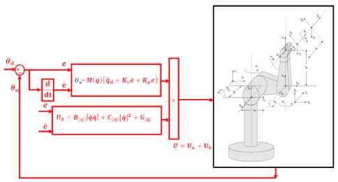
Fig 1: PD CTC with application to rigid manipulator
When all dynamic and physical parameters are known computed torque controller works superbly; practically a large amount of systems have uncertainties and PD plus gravity controller reduce this kind of limitation.
-
C. PD Plus Gravity Methodology
A useful family of computed torque controller (CTC) is PD plus Gravity which the results when M = I,N = G(q^. Based on CTC method and uncertainty in dynamic formulation, this method is defined by the following formulation;
т = M(q)(q d + Kve + Kpe) + G(q)(7)
If the Lyapunov function in this method defined as follows;
V = (D^) xqTxq) + (eTKpe)
and the differentiate to obtain
V = (qT )(M(q) xq + 1q M- Kpe)
Based on CTC formulation and Lyapunov formulation in CTC;
V = (qT)(1M(q) — (N(q, q) + G(q)) x(Ю)
q = qTK v q
Therefore the skew symmetry of the first term is given by;
V = -qTKvq(11)
Based on above formulation this methodology has demonstrate stability in the sense of Lyapunov in bounded of error and joint velocity when V is negative.
-
D. Fuzzy Logic Methodology
Based on foundation of fuzzy logic methodology; fuzzy logic controller has played important rule to design nonlinear controller for nonlinear and uncertain systems [16-17]. However the application area for fuzzy control is really wide, the basic form for all command types of controllers consists of; Input fuzzification (binary-to- fuzzy [B/F] conversion) Fuzzy rule base (knowledge base), Inference engine and Output defuzzification (fuzzy-to-binary [F/B] conversion). Figure 2 shows a fuzzy controller part.
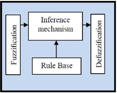
Fig 2: Fuzzy Controller Part
The fuzzy inference engine offers a mechanism for transferring the rule base in fuzzy set which it is divided into two most important methods, namely, Mamdani method and Sugeno method. Mamdani method is one of the common fuzzy inference systems and he designed one of the first fuzzy controllers to control of system engine. Mamdani’s fuzzy inference system is divided into four major steps: fuzzification, rule evaluation, aggregation of the rule outputs and defuzzification. Michio Sugeno use a singleton as a membership function of the rule consequent part. The following definition shows the Mamdani and Sugeno fuzzy rule base
if x is A and y is B then z is C 'mamdani' (12) if x is A and y is B then z is f(x, y)'sugeno'
When x and у have crisp values fuzzification calculates the membership degrees for antecedent part. Rule evaluation focuses on fuzzy operation (AND /07?) in the antecedent of the fuzzy rules. The aggregation is used to calculate the output fuzzy set and several methodologies can be used in fuzzy logic controller aggregation, namely, Max-Min aggregation, Sum-Min aggregation, Max-bounded product, Max-drastic product, Max-bounded sum, Max-algebraic sum and Min-max. Two most common methods that used in fuzzy logic controllers are
Max-min aggregation and Sum-min aggregation. Maxmin aggregation defined as below;
Ци (Хк,Ук,и) = Hur=1FR* (Хк,Ук,и) (13)
= max {minU [^Rpq (Xk, yk), Hpm (U)]j
The Sum-min aggregation defined as below
Hu (xk, Yk,U) = Ц^ FRi (xk, yk,U) (14)
= ^ mmr^ [^Rpq (xk,yk), ^pm (U)]
where r is the number of fuzzy rules activated by xk and yk and also ^г ^FRi(xk , yk , U) is a fuzzy interpretation of i — th rule. Defuzzification is the last step in the fuzzy inference system which it is used to transform fuzzy set to crisp set. Consequently defuzzification’s input is the aggregate output and the defuzzification’s output is a crisp number. Centre of gravity method (COG) and Centre of area method (COA) are two most common defuzzification methods, which COG method used the following equation to calculate the defuzzification
COG(x k ,y k )
Si Ui Sj=1- ^u (xk, yk, Ui)
Si Sj=1- Hu (xk, yk, Ui)
and COA method used the following equation to calculate the defuzzification
COA(x k ,y k )
Si Ui. Mxk^Ui)
Si Hip (xbYk, Ui)
Where COG(xk, yk) and C0A(xk, yk) illustrates the crisp value of defuzzification output, Ui E U is discrete element of an output of the fuzzy set, д0. (xk, yk, Ui) is the fuzzy set membership function, and r is the number of fuzzy rules.
-
III. METHODOLOGY
The method of computed torque control works quite well, and we can have better control than linear PD or PID control, but only if we have all necessary information about nonlinear dynamic formulation of system and the parameters of robot manipulator. These are very hard to have in practice. At the same time, the dynamics of the robot can change during the process, and that can affect the result of the control, too. In this case the result of CTC can decrease because the inquiry of dynamic model. To avoid of this situation fuzzy logic method can applied to PD plus gravity method to estimate uncertainty and nonlinear part which it is caused to reduce the performance quality. In this case we can achieve the desired settling time and we can achieve very small steady state tracking errors. Based on fuzzy logic methodology
M (17)
f(x) = U fuzzy = /9T Z(x)
l=1
where 9T is adjustable parameter (gain updating factor) and <(x) is defined by
_ 5 H(x i )x i (18)
Z(x) = 5 H(x i )
Where /i(x , ) is membership function. T y uzzy is defined as follows;
T fuzzy = 5 M=1 9T Z(x) = B (q) [q q] + (19)
C(q)[q]2
This methodology has three main parts; linear PD part based on PD linear formulation, nonlinear gravity part to eliminate the term of gravity and fuzzy like nonlinear equivalent part to eliminate the nonlinearity part. Based on this methodology;
T = M(q)(q d + Kve + Kpe) + G(q) +
5 =1 9T Z(x)
If the Lyapunov function in this method defined as follows;
V = (1)(M(q) xqT x q) + (eTKpe) +
-
2 5 =1 Y j Фт. Ф J
and the differentiate to obtain
V = (qT )(M(q) xq + =q M- Kpe) +
5jM=1^ Фт. Ф 1
-
Y J
Based on (10) and (11);
V = (qT)(1M(q) - (N(q, q) + G(q)) x q + ZM=17ФТ. Ф, =qTKvq +
Y j
5 M=1 Y- фт. Ф
Therefore the skew symmetry of the first term is given by;
V = -q T K v q -5jM=17 Фт. Ф j (24)
y j
The proposed methodology is shown in Figure 3.
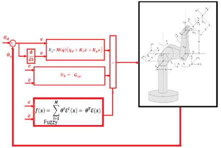
Fig 3: Block diagram of proposed fuzzy PD plus gravity with application to robot manipulator
-
IV. RESULTS AND DISCUSSION
Proposed fuzzy PD plus gravity (proposed) and PD plus gravity controller (PDG) was used to decrease the error. The simulation was implemented in MATLAB/SIMULINK environment.
Tracking performances: based on proposed formulation in PD plus gravity method and fuzzy PD plus gravity method; the performance of these controllers are depended on the PD (Kp and K „ ) and gain updating factor coefficients. These factors are calculated by optimization method.
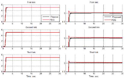
Fig 4: Tracking performance; fuzzy PD gravity methodology and PD gravity method
Based on simulation results the Steady State and RMS error in proposed method (Steady State error =1e-6 and RMS error=1.2e-6) are fairly lower than PDG’s (Steady State error = — 3e — 5 and RMS error= —1.34e — 5 ) Based on Figure it is found fairly fluctuations in trajectory responses. Based on Figure 4, this trajectory performance is used for comparisons of above controllers in certain systems. In this state proposed method and conventional PD plus gravity with have an acceptable trajectory performance.
Disturbance rejection: Figure 5 shows the proposed and pure PD plus gravity in presence of 15% disturbance. Figure 5 shows the power disturbance elimination in these two types of controller. The disturbance rejection is used to test the robustness comparisons of these two controllers for desired trajectory. A band limited white noise with predefined of 15% the power of input signal is applied to the trajectory. It found fairly fluctuations in trajectory responses.
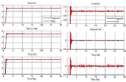
Fig 5: Disturbance rejection; fuzzy PD gravity methodology and PD gravity method
Based on Figure 5; by comparing response trajectory with 15% disturbance of relative to the input signal amplitude in fuzzy PD gravity method and gravity method, fuzzy PD gravity method’s overshoot about (1%) is lower than gravity method’s (9.1%). fuzzy PD gravity method’s rise time (0.5) is lower than PD gravity method’s (0.53). Besides the Steady State and RMS error in fuzzy PD gravity method (Steady State error =1.6e-6 and RMS error=1.9e-6) are fairly lower than PD gravity method’s (Steady State error = 0.003 and RMS error=0.0048). Based on Figure 5, PD gravity method has oscillation in trajectory response with regard to 15% of the input signal disturbance but fuzzy PD gravity method is more robust.
-
V. CONCLUSION
In this research, we develop a robust model free dynamical controller for solving the problem of tracking and regulation for both of certain and uncertain dynamic parameters. The design of the controller is based on eliminate the gravity of rigid link manipulator and estimate the centrifugal torques and coriolios torques parameters of robot manipulator by artificial intelligence method. Stability conditions imposed the output performance is insensitive to the disturbances. Furthermore, PD plus gravity method is investigated for comparative purpose. In this research the main control objective is to achieve sufficiently small tracking error. In order to increase the influence of disturbances on dynamic properties of the output trajectories, a high feedback gain, and a higher order output derivatives in the feedback loop are used. By simulation it was shown that the proposed fuzzy PD gravity method yields better results that conventional PD gravity method.
ACKNOWLEDGMENT
The authors would like to thank the anonymous reviewers for their careful reading of this paper and for their helpful comments. This work was supported by the SSP Research and Development Corporation Program of Iran under grant no. 2012-Persian Gulf-3C.
References A Design High Impact Lyapunov Fuzzy PD-Plus-Gravity Controller with Application to Rigid Manipulator
- T. R. Kurfess, Robotics and automation handbook: CRC, 2005.
- J. J. E. Slotine and W. Li, Applied nonlinear control vol. 461: Prentice hall Englewood Cliffs, NJ, 1991.
- B. Siciliano and O. Khatib, Springer handbook of robotics: Springer-Verlag New York Inc, 2008.
- F. T. Cheng, T. L. Hour, Y. Y. Sun and T. H. Chen, "Study and resolution of singularities for a 6-DOF PUMA manipulator," Systems, Man, and Cybernetics, Part B: Cybernetics, IEEE Transactions on, No. 2, vol. 27, pp. 332-343, 2002.
- M. W. Spong and M. Vidyasagar, Robot dynamics and control: Wiley-India, 2009.
- A. Vivas and V. Mosquera, "Predictive functional control of a PUMA robot," Conference Proceedings, 2005.
- D. Nguyen-Tuong, M. Seeger and J. Peters, "Computed torque control with nonparametric regression models," IEEE conference proceeding, 2008, pp. 212-217.
- Farzin Piltan, Reza Bayat, Saleh Mehrara, Javad Meigolinejad “GDO Artificial Intelligence-Based Switching PID Baseline Feedback Linearization Method: Controlled PUMA Workspace,” International Journal of Information Engineering and Electronic Business (IJIEEB), 4 (5):17-26, 2012.
- Farzin Piltan, Bamdad Boroomand, Arman Jahed, Hossain Rezaie " Performance-Based Adaptive Gradient Descent Optimal Coefficient Fuzzy Sliding Mode Methodology". International Journal of Intelligent Systems and Applications (IJISA), 4 (11), 40-52, 2012.
- Farzin Piltan, Nasri Sulaiman, M. H. Marhaban and R. Ramli, “Design On-Line Tunable Gain Artificial Nonlinear Controller,” Journal of Advances In Computer Research, 2 (4): 75-83, 2011.
- Farzin Piltan, N. Sulaiman, A. Jalali & F. Danesh Narouei, “Design of Model Free Adaptive Fuzzy Computed Torque Controller: Applied to Nonlinear Second Order System,” International Journal of Robotics and Automation, 2 (4):232-244, 2011.
- Farzin Piltan, N. Sulaiman, Payman Ferdosali, Mehdi Rashidi, Zahra Tajpeikar, “Adaptive MIMO Fuzzy Compensate Fuzzy Sliding Mode Algorithm: Applied to Second Order Nonlinear System,” International Journal of Engineering, 5 (5): 380-398, 2011.
- Farzin Piltan, SH. Tayebi HAGHIGHI, N. Sulaiman, Iman Nazari, Sobhan Siamak, “Artificial Control of PUMA Robot Manipulator: A-Review of Fuzzy Inference Engine And Application to Classical Controller ,” International Journal of Robotics and Automation, 2 (5):401-425, 2011.
- Samira Soltani & Farzin Piltan, “Design Artificial Nonlinear Controller Based on Computed Torque like Controller with Tunable Gain”. World Applied Science Journal,14 (9): 1306-1312, 2011.
- Farzin Piltan, M. Keshavarz, A. Badri, A. Zargari , ”Design novel nonlinear controller applied to robot manipulator: design new feedback linearization fuzzy controller with minimum rule base tuning method” International Journal of Robotics and Automation, 3(1): 1-18, 2012.
- Farzin Piltan , M.H. Yarmahmoudi, M. Shamsodini, E.Mazlomian, A.Hosainpour. ” PUMA-560 Robot Manipulator Position Computed Torque Control Methods Using MATLAB/SIMULINK and Their Integration into Graduate Nonlinear Control and MATLAB Courses” International Journal of Robotics and Automation, 3(3): 2012.
- Farzin Piltan, R. Bayat, F. Aghayari, B. Boroomand. “Design Error-Based Linear Model-Free Evaluation Performance Computed Torque Controller” International Journal of Robotics and Automation, 3(3): 2012.
