A Frequency Estimation for TD-SCDMA UE Based on Phase Difference

Author: Ren-ming Peng, Zheng-tong Hao, Yang Mei
Journal: International Journal of Computer Network and Information Security(IJCNIS) @ijcnis
Article in issue: 3 vol.3, 2011.
Free access
This paper describes a new method of frequency estimation in cell search of TD-SCDMA system. Before identifying the scrambling code and Midamble code, using part of sync-dl code data for frequency estimation; and before controlling the multi-frame synchronization, using part of Midamble code data for frequency estimation. Also these two sets of estimation can be done under the same frequency estimation structure by using the same 64 chip input in order to save hardware resources. The simulation results show that even with certain sample differences, this method can keep the residual frequency differences within 0.05 PPM by averaging out the subframe or by IIR filtering to satisfy the requirement of frequency estimation for TDSCDMA system.
TD-SCDMA, sync-dl, cell search, frequency offset estimation
Short address: https://sciup.org/15011023
IDR: 15011023
Text of the scientific article A Frequency Estimation for TD-SCDMA UE Based on Phase Difference
Published Online April 2011 in MECS
In Time Division Synchronous Code Division Multiple (TD-SCDMA) system, both base stations and terminals use a standard carrier frequency to transmit and receive signals. 3GPP (The 3rd Generation Partnership Project) requires the carrier frequency differences of base station to be less than 0.05PPM[1], or about 100Hz, the carrier frequency differences of user terminal to be less than 0.1PPM [2], or about 200 Hz. At the base station, because of less restriction of temperature, volume, power, wasted work, and cost, etc., the frequency accuracy of crystal oscillator can easily meet the requirement. But at the terminal, because of the limits of the factors listed above, the frequency accuracy of the selected crystal oscillator usually can not meet the requirement. Therefore, a certain frequency difference exists between the actual signal sending and receiving end.
In addition, the terminal mobile forms Doppler shift also causes frequency differences between sending and receiving devices. Especially in the environment of high speed rail-road, high speed movement causes relatively larger Doppler frequency shift between sending and receiving signals at the terminal. For example, Shanghai-Nanling high speed rail-road line started operation in July, 2010 and the top speed could reach 350 km/ h, which could cause Doppler frequency shift to be around 650 Hz at most.
Because of the two reasons mentioned above, they may lead to relatively large frequency differences between sending and receiving, which in turn could affect the performance of receiver, lower the quality of phone call, even cause cutting off calls and disconnecting them. Therefore, whether or not being able to quickly and accurately estimate and adjust the frequency differences is an essential step for correctly receiving data and keeping normal communication for a mobile communication system [3].
In order to have a successful cell search for TD-SCDMA terminal, it needs frequency differences estimation and compensation as soon as possible. Generally speaking, TD-SCDMA terminal can use data segment in sub-frame structure and PN (Pseudorandom Noise) sequence data segment, as known as SYNC-DL code, Midamble code [4], for frequency differences estimation. At the beginning of cell search, the terminal can not carry out data demodulation. Therefore, without demodulated data for frequency differences estimation at this stage forces people to use SYNC-DL code or Midamble code for this purpose.
During the terminal cell search, time synchronization accuracy is not high, and there is no priori channel information. As a result, the initial frequency differences range is generally large. Because of the high standard requirements for terminal chip area and wasted work, the cell search time can not be too long to affect clients' experience. It requires simple calculation, easy implement, as well as insurance of certain degree of reception quality. Therefore, a fast, stable, and better quality of algorithm method for frequency differences estimation is the focus of research.
In 1966, Andrew J. Viterbi proposed a classic frequency differences estimation method which was based on maximum likelihood [5]. In 1974, D. Rife and R. Boorstyn presented a classic algorithm of closing CRS (Cramer-Rao ) boundary[6]. Based on the works of the people mentioned earlier, in 1995, M. Luise and R.Reggiannin presented an improved approximation algorithm [7]. The frequency differences estimation range of this algorithm is:
A f <--- NTs
( 1 )
Where, N is the length of chip sequence, Ts is the chip duration.
For 1.28 Mcps (Million chip per second) TD- SCDMA system, use 64-chip, single sample SYNC-DL code for frequency differences estimation:
A f < 1/64/(1/(1.28*10л6)) = 20000 ( 2 )
The frequency differences estimation range is ± 20 k Hz.
The frequency differences estimation algorithm is:
n
R(k) = £ rr- k i=K+1
A f =
N
£ k Im{ R ( k )}
1 k =1 ________________________
2nT £k2Re{R(k)} k=1
-
( 3 )
-
( 4 )
Where, r is the sequence of received training sequences and local training code sequences multiplied by conjugate sequence.
In the environment of Gaussian channel, this algorithm can get better performance, but in fading channel, above algorithm performance deteriorated quickly. So for fading channel, other methods of frequency differences estimation were proposed.
In 1997, Wen-Yi Kuo and M. P. Fitz proposed the maximum likelihood frequency differences estimation method and its approximation method for flat fading channel under the condition of known Doppler bandwidth [8]. In 1998, M. Morelli, U. Mengali and G. M. Vitetta improved this method [9]. Their major improvements include expanding frequency differences estimation range and Doppler bandwidth estimation.
In 1998, M. G. Hebley and D. P. Taylor presented the frequency differences estimation algorithm for selected channel under the premise of knowing channel parameters [10]. In 2000, M. Morelli and U. Mengali proposed another algorithm, which didn't require channel parameters, and suggested the frequency differences estimation range is [11]:
A f < ^T ( 5 )
For 1.28 Mcps (million chip per second) TD-SCDMA system,
A f < 1/2/(1/(1.28 x 10Л6)) = 640000 ( 6 )
The frequency differences estimation range is ± 640 k Hz.
The frequency differences estimation algorithm:
Premise some frequency differences values, such as Δf, 0, Δf, 2Δf, etc. , calculate local training code B matrix:
B = A(AHA)-1 AH,
[ A ]j = a-j
N - 1
P(m) = £ [B]k-m,k x(k)x* (k - m)
k = m
Where, ai is local training sequence, x is received training sequence.
Search for a frequency difference Af, and find the greatest of following equation:
N - 1
g (A f) = - p (0) + 2Re{ £ p( m) e - j2 A fT s } ( 10 ) m = 0
The algorithm mentioned above can get better performance in fading channel environment. But this algorithm is complicated, includes matrix calculation, and particularly includes matrix inversion process. The accuracy of this algorithm depends on the setting of frequency intervals. In order to have higher accuracy, it needs to search multiple frequency points, which is not easy to achieve. At the mean time, it doesn't meet the requirements of saving terminal chip area and wasted work.
Besides the methods mentioned above, estimation of phase change within a certain time period can also be used for indirect estimating of frequency differences [12].
Set sequence length to N, r is the different sequence between received training code sequence and local training code sequence conjugate multiplied, then removed the phase effect of the initial stage sequence. Calculate average value of the first half of this different sequence and the average value of its second half, then multiply these two values conjugate:
A9 = arg( mean ( r (1: N / 2))* conj ( mean ( r ( N /1 +1: N ))))
The phase difference calculated from the equation above and the frequency calculated based on the time difference between the first and second half of the time intervals:
A f = A9 /(2 n )/( T s * N /2) ( 12 )
In this paper, by combining TD-SCDMA system, subframe structure, and TD-SCDMA terminal cell search process, we propose a frequency differences estimation method based on phase difference estimation. This method can solve the problem of frequency differences estimation for TD-SCDMA terminal cell search quite well under different channel conditions. Meanwhile, it is simple, relatively easy to implement.
-
II. TD-SCDMA SYSTEM SUB - FRAME STRUCTURE
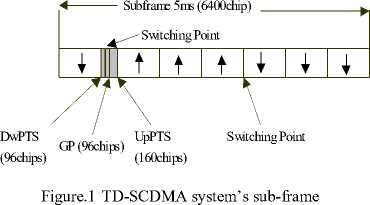
According to the requirements of TD-SCDMA communication system, its sub-frame structure and time slot structure are shown in Figure 1. TD-SCDMA frame is 10 ms long. It is divided into two identical sub-frame structures. Each sub-frame structure has seven regular time slots of 675us and 3 special slots. These three special slots are DwPTS (downlink pilot time slot), GP (protected slot), and UpPTS (uplink pilot time slot ). Among the seven regular time slots, Ts0 is always assigned to downlink chain line, and Ts1 assigned to uplink chain line. Uplink and downlink time slots are separated by transition points. In TD-SCDMA system, there are two transition points for every 5ms sub-frame structure (UL to DL, and DL to UL). Using received time slot data, Midamble code and DwPTS signals can estimate terminal frequency differences
1.28Mcps
|
Data symbols 352 chips |
Midamble 144 chips |
Data symbols 352 chips |
GP 16 CP |
864*T c
Figure. 2 Time slot structure for TD-SCDMA system.
75us
GP(32chips) SYNC_DL(64chips)
Figure. 3 Bursting structure of DwPTS.
Cell search process of TD-SCDMA system can be divided into four steps:
-
1) Search DwPTS.
There are 32 downlink synchronization codes SYNC-DL in TD-SCDMA system. The downlink synchronization codes launch to all directions in downlink pilot frequency time slot, neither scrambling codes nor spreading spectrum. UE with the matched filter (or similar devices) to the received SYNC-DL are one to one correspondence with 32 known downlink pilot frequency codes, so the cell used the SYNC-DL can be known, also can determine the synchronization position.
-
2) Scrambling code and the Midamble code’s identification
Each SYNC-DL code corresponds to a group of four Midamble codes; P-CCPCH uses one of them. When the SYNC-DL identifies, the group of Midamble code can be known. Used four possible Midamble codes to test one by one, P-CCPCH used the Midamble code can be finally defined. In addition, Midamble code and scrambling code are one-to-one correspondence, so when Midamble code is confirmed, scrambling code used P-CCPCH is also determined.
TABLE I
SYNC-DL S EQUENCE OF P HASE M ODULATION
|
Name |
Four Consecutive phases |
Means |
|
S1 |
135, 45, 225, 135 |
Following four sub-frames are P-CCPCH |
|
S2 |
315, 225, 315, 45 |
Following four sub-frames are not P-CCPCH |
3) Control Multi-frame synchronization
BCH broadcast information is distributed in four consecutive 5ms sub-frames. To correctly read the BCH information, UE must first determine the starting position in P-CCPCH of the BCH’s multi-frame. To get the starting and ending positions of this process is called control Multi-frame synchronization. This location is relative to the SYNC-DL code 0 time slot of Midamble code to indicate the phase QPSK modulation, 3GPP protocol [6,7] states the following:
UE continuously reads DwPTS, and determines the phase. When the phase of four consecutive DwPTS are agreement with Table 1. of S1, That the next sub-frame is the beginning of sub-frames BCH can be determined.
-
4) Read BCH
P-CCPCH carrying the BCH, P-CCPCH’s spreading code is the SF of 16’s first two codes. When the spreading code and scrambling code of P-CCPCH is identified, the BCH sub-frame’s starting position is also determined. The BCH information can be successfully read
This paper mainly studies the second step and the third step of the FOE.
-
III. S EARCH F REQUENCY D IFFERENCES E STIMATION
Considering the FOE in cell search process is as follows:
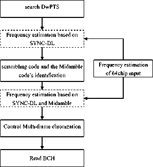
Figure.4 Frequency estimation of cell search process
A.the FOE before identification of the scrambling code and Midamble code
To improve the accuracy of Midamble code identification, generally requires the FO under 5000Hz. As in the cell search steps (1) the DwPTS has been determined, the SYNC-DL code of 64chip in DwPTS can be used to estimate the FO. Using the classical method of phase difference to calculate the FO, as follows:
-
1) . Calculated the related values of before 32chip and after the 32chip of receiving SYNC-DL code.
CorrS = receives x conj (localS )
which, receives S is the part of the data of SYNC-DL code, and localS is the local SYNC-DL code:
S1 = sum (CorrS (1:32))(14)
S 2 = sum (CorrS (33:64))(15)
S1 is the SYNC-DL code of relevant results of the first 32chip, S2 is the SYNC-DL code of relevant results of after the 32chip.
-
2) . Calculated the complex of the relevant phase difference before and after the two plural:
S = S 2 x conj ( S 1) (16)
-
3) . Calculation of phase deviation
Phase = agc tan(imag ( S ) / real ( S )) (17)
-
4) . Calculation of the FOE
Freguency = Phaset /(2 x n x 32) x 1280000 (18)
1280000 is the code chip’s speed (1.28Mcps) of TD-SCDMA system.
B.Control of the FOE before Multi-frame synchronization
Cell search step (2) correctly identifies the Midamble code, to complete control multi-frame synchronization and subsequent demodulation BCH, the phase of four consecutive DwPTS should be calculated. Residual frequency offset on system requirements higher than step (2); otherwise influence the control of multi-frame synchronization’s probability of success and BCH demodulation performance. Also the SYNC-DL code and Midamble code to estimate the frequency offset can be used, as follows:
-
1) . Calculation of the relevant value of the first and the second 32chip of receiving Midamble code
CorrM = receiveM(1: 64) x conj(localM(1: 64))
receiveM is the part data of receiving Midamble code; localM is the local Midamble code.
M1 = sum(CorrM (1: 32))(20)
M 2 = sum (CorrM (33:64))(21)
M1 and M2 are the Midamble code’s relevant value of the first 32chip and the second 32chip, respectively.
-
2) . Calculate the complex of the first 32chip, the second 32chip’s relevant phase difference
M 3 = M 2 x conj ( M 1) (22)
-
3) . Same steps to calculate the third 32chip and the forth 32chip’s relevant phase difference of the complex M4.
-
4) . Using III. A of step 1 and step 2 to calculate the complex S of the SYNC-DL code’s the phase difference before and after the two plural.
-
5) . Accumulating phase difference of the complex:
MS = M 3 + M 4 + S(23)
-
6) . Calculated phase deviation
Phase = arctan(imag (MS) / real (MS))(24)
-
7) . Calculated frequency offset
Freguency = Phaset /(2 x nx 32) x 1280000(25)
Of which 1.28 million is the TD-SCDMA system’s code chip speed rate 1.28Mcps.
-
IV. S IMULATION AND A NALYSIS
In this paper, the scrambling code and Midamble code identification before the FOE in the part (III.A) and the control of multi-frame synchronization before the FOE’s algorithm in the part (III.B) are simulated.
Simulation Environment
Simulation of the accuracy in part III.A and III.B of the FOE’s method, simulating environment as follows:
TABLE II
S IMULATING S YSTEM P ARAMETERS
|
System parameters |
Values |
|
Channel condition Ior/Ioc samples deviation The ID of SYNC-DL code The ID of Midamble code The statistical number of times Frequency offset Statistic |
AWGN 、 CASE1 、 CASE2 、 CASE3 AWGN : [-10:2:20]dB CASE1/CASE2/CASE3 : [-5:2:25]dB [0 1/8 1/4 3/8 1/2]chip 0 0 2000 0Hz/1000Hz The mean and standard deviation |
Propagation conditions
Static propagation condition (AWGN) : The propagation for the static performance measurement is an Additive White Gaussian Noise (AWGN) environment. No fading and multi-paths exist for this propagation model.
Multi-path fading propagation conditions: table iii shows propagation conditions that are used for the performance measurements in multi-path fading environment. All taps have classical Doppler spectrum.
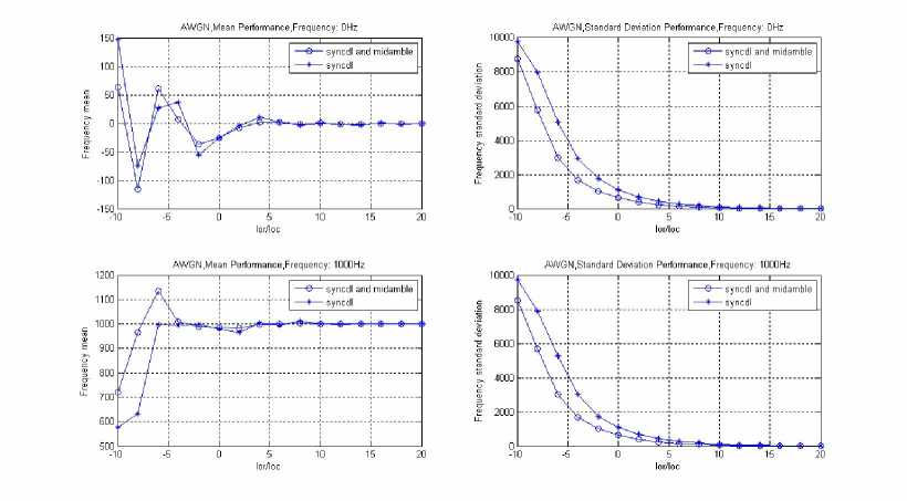
Figure 5. FOE under AWGN channel
TABLE III
Propagation Conditions for Multi-Path Fading Environments operations [2]
|
Case 1 |
Case 2 |
Case 3 |
|||
|
Speed for operating band a, b, c, f: 3km/h |
Speed for operating band a, b, c, f: 3km/h |
Speed for operating band a, b, c, f: 120km/h |
|||
|
Relative Delay [ns] |
Relative Mean Power [dB] |
Relative Delay [ns] |
Relative Mean Power [dB] |
Relative Delay [ns] |
Relative Mean Power [dB] |
|
0 |
0 |
0 |
0 |
0 |
0 |
|
2928 |
-10 |
2928 |
0 |
781 |
-3 |
|
12000 |
0 |
1563 |
-6 |
||
|
2344 |
-9 |
||||
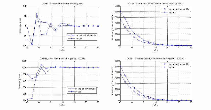
Figure 6. FOE under CASE1 channel
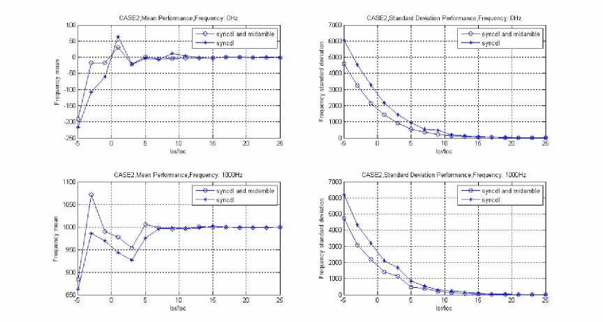
Figure 7 FOE under CASE2 channel.
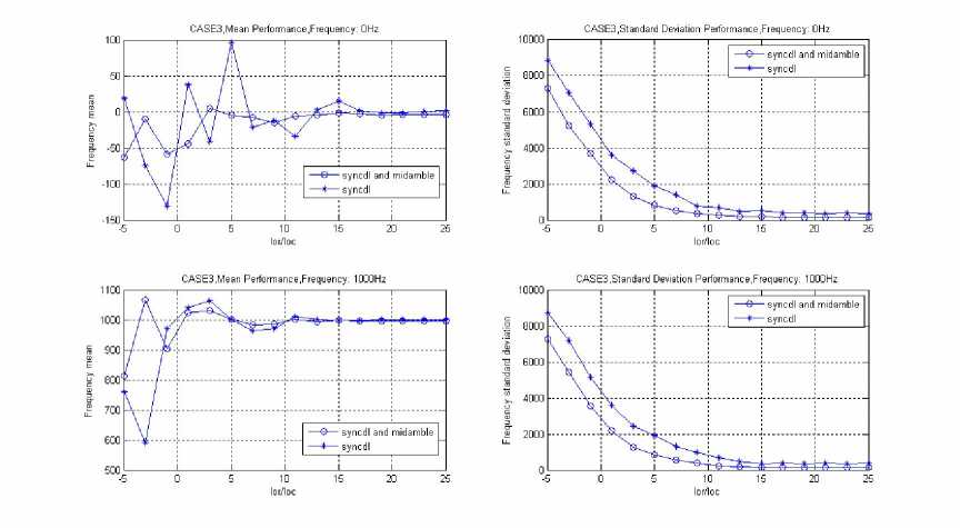
Figure 8 FOE under CASE3 channel.
Form Figure 5 to Figure 8 are the simulating results under the 3GPP agreement of the four kinds of channel environment: AWGN, CASE1, CASE2 and CASE3. The figures showed the mean and standard deviation curves of various channel environments, the default of frequency offset: 0Hz and 1000Hz, and the signal noise ratio(SNR) of the frequency estimation which, under the AWGN channel environment, the simulating SNR range is [-10: 2: 20]dB. It showed from the beginning of -10dB, interval of 2dB, to 20dB;
Under the CASE1, CASE2, CASE3 channel environment, the simulating SNR range is [-5: 2: 25]dB. It showed form the beginning of -5dB, interval of 2dB, to 25dB.
"sync" illustrates the estimating curve, which is the second step of cell search for the scrambling code and Midamble code identification before the frequency offset estimation;
"sync + mid" illustrates the estimating curve, which is the third step of cell search for controlling complex frame synchronization before the method of frequency offset estimation.
From Figure5, Figure 6, Figure 7 and Figure 8, the simulation results showed that:
-
(1) Because FOE mean value of SYNC-DL code is within 500 Hz, it meets the requirement for Midamble code identification; and FOE mean value of Midamble Code plus SYNC-DL Code is within 100Hz, it also meets the requirement for controlling of multi-frame synchronization and BCH demodulation.
-
(2) Calculating steps 1- 2 of 3.1 and steps 1-2 of 3.2, as well as steps 3-4 of 3.1 and steps 5-6 of 3.2 went through exactly the same process, as shown in Figure 3., we can use same module to implement. This is good for reusing of FPGA or ASIC hardware module.
-
(3) .Both FOE of 3.1 and 3.2 has a certain standard difference. Before AFC compensation, it needs average of multi-sub-frames or first order IIR filter to smooth out frequency offset estimation value in order to make residual frequency offset to satisfy the requirement of TD-SCDMA system after AFC compensation to FOE.
-
V. C ONCLUSION
Four steps of TD-SCDMA system Cell Search Process and several key steps which requires frequency offset are introduced in this paper. Also this paper analyzed those useful data for FOE in each step. Before identifying scrambling and Midamble code, it already determined SYNC-DL code identification. Then use 64 chip data of part of SYNC-DL code to achieve FOE. Before controlling of multi-frame synchronization, Midamble code identification was determined. Then divide the 128 chip Midamble code data into two 64 chip data segments for FOE. So FOE can use same 64 chip input structure to save resources. This is suitable for FPGA or ASIC hardware implementation. Simulating results showed that even with some sample differences, by using average of multi-sub-frames or IIR filter, it is also able to lock residual frequency offset within 0.05ppM to meet the requirements for TD-SCDMA system frequency offset. Simulation results show that the phase difference method used to estimate the frequency offset, in the 3GPP agreement of four channels environment: AWGN, CASE1, CASE2 and CASE3, through the average of multiple sub-frame or IIR filter, to control the residual frequency offset within the 0.05PPM, to satisfy the requirements of frequency offset of TD-SCDMA system cell search, to ensure the terminals of completing the process of cell search successfully.
-
[8] W. Kuo, M.P. Fitz, Frequency offset compensation of pilot symbol assisted modulation in frequency flat fading , IEEE Trans. on Commun., 1997, 45(11): 1412-1416.
-
[9] M. Morelli, U. Mengali, and G. M. Vitetta, Further results in carriefrequency estimation for transmissions over flat fading channels, IEEE Commun. Lett., vol. 2, no. 12, pp. 327-330, Dec. 1998
-
[10] M. G. Hebley and D. P. Taylor, The effect of diversity on a burst-carrier-frequency estimator in the frequency-selective multip channel, IEEE Trans. Commun., vol. 46, pp. 553560, Apr. 1998
-
[11] M. Morelli and U. Mengali, Carrier-frequency estimation for transmissions over selective channels. IEEE Trans. Comm. 48 (2000), pp. 1580-1589.
-
[12] Fowler, M. L., Phase-Based Frequency Estimation: A Review, Digital Signal Processing12 (2002) 590-615.
-
[13] 3GPP TS 25.223 V9.0.0 (2009-12): Spreading and modulation (TDD) (Release 9).

Ren-Ming Peng, Ren-Ming Peng was born in China, in 1969. He received the B.S. degree in electronic and communication engineering from Chongqing University in 2004. He has been a Faculty Member with School of physics & Electronic Engineering, Mianyang Normal University. His current research interests in electronic
and communication technology.

A CKNOWLEDGMENT
This work is supported by Mianyang Normal University Science and Technology research Fund (MQD2008A001).
References A Frequency Estimation for TD-SCDMA UE Based on Phase Difference
- 3GPP TS 25.105 V9.2.0 (2010-09): Base Station (BS) radio transmission and reception (TDD) (Release 9).
- 3GPP TS 25.102 V9.3.0 (2010-12): User Equipment (UE) radio transmission and reception (TDD) (Release 9).
- U. Mengali, AND Andrea. Synchronization Techniques for Digital Receivers.New York: PlenumPress, 1997. 9-95.
- 3GPP TS 25.221 V9.3.0 (2010-09): Physical channels and mapping of transport channels onto physical channels (TDD) (Release 9).
- J. Andrew. Viterbi, Principles of Coherent Communication, McGraw-Hill, New York, [1966].
- D. Rife, R. Boorstyn. Single-tone parameter estimation from discrete-time observations. IEEE Transactions on Information Theory, 1974, 20(5): 591-598.
- M. Luise, R. Reggiannini. Carrier frequency recovery in all-digital modems for burst-mode transmission [J]. IEEE Trans. Commun., 1995-02-03-04, 43: 1169-1178.
- W. Kuo, M.P. Fitz, Frequency offset compensation of pilot symbol assisted modulation in frequency flat fading,IEEE Trans. on Commun., 1997, 45(11): 1412-1416.
- M. Morelli, U. Mengali, and G. M. Vitetta, Further results in carriefrequency estimation for transmissions over flat fading channels, IEEE Commun. Lett., vol. 2, no. 12, pp. 327-330, Dec. 1998
- M. G. Hebley and D. P. Taylor, The effect of diversity on a burst-carrier-frequency estimator in the frequency-selective multip channel, IEEE Trans. Commun., vol. 46, pp. 553-560, Apr. 1998
- M. Morelli and U. Mengali, Carrier-frequency estimation for transmissions over selective channels. IEEE Trans. Comm. 48 (2000), pp. 1580-1589.
- Fowler, M. L., Phase-Based Frequency Estimation: A Review, Digital Signal Processing12 (2002) 590-615.
- 3GPP TS 25.223 V9.0.0 (2009-12): Spreading and modulation (TDD) (Release 9).
