A mobile application of augmented reality for aircraft maintenance of fan cowl door opening

Author: Sei Wei Yong, Aun Naa Sung
Journal: International Journal of Computer Network and Information Security @ijcnis
Article in issue: 6 vol.11, 2019.
Free access
Maintenance error such as failure of fan cowl door opening is one of the causes of aircraft accidents. In this research, we aim to develop an augmented reality application that allows the animation of each maintenance procedure of fan cowl door opening to be superimposed on the fan cowl door of aircraft. The marker detectability of the augmented reality application is checked based on different camera angles and distances. Hence, by using the developed application, the aircraft maintenance technician can interpret the information of the fan cowl door opening procedure in the form of texts, three-dimensional models and animations.
Augmented reality, aviation, aircraft maintenance, mobile application, user interaction, marker-based
Short address: https://sciup.org/15015695
IDR: 15015695 | DOI: 10.5815/ijcnis.2019.06.05
Text of the scientific article A mobile application of augmented reality for aircraft maintenance of fan cowl door opening
Published Online June 2019 in MECS
The level of safety in aviation becomes an important issue due to the rapid volume growth of worldwide air transportation traffic [1]. In order to reduce the occurring of aircraft accident, the root causes of aviation accident have been identified. The root causes include human error, mechanical failure, hazardous weather, sabotages and military operations [2]. The human error contributes to 70 – 80% of aviation accidents [3]. The human error occurs in the production, operation and maintenance of aviation [2]. The human error exists in maintenance when the aircraft maintenance technician (AMT) performs a complicated maintenance and inspection task with sparse feedback and time pressure [4]. Various types of error occur when generic human erring tendencies are in combination with these situational characteristics. Since the human error in the maintenance is a risk to aviation safety, there are multiple stimulation and computer-based tools have been developed to reduce human errors [5]. The computer-based tool, such as Augmented Reality (AR) has been introduced in aircraft maintenance. By introducing AR the required information can be obtained at the right time, thus, the effectiveness of the aircraft maintenance system is improved [6].
AR is a technology which combined the computergenerated virtual information with the real environment [7]. The information in the form of text, sound, graphics or animation can be accessed and interpreted easily through AR [8]. In aircraft maintenance, step by step Aircraft Maintenance Manual (AMM) procedure can be accessed by AMT when working with the equipment. As a result, AMT is able to reduce head and eye movement, reduce context switching and reduce time for repair sequence transitions while performing maintenance work [9]. This study aims to develop an AR mobile application to display the AMM procedure step-by-step in the form of text and animations for fan cowl door opening of engine CFM 56-5B.
-
II. Related Works
Several researchers have developed AR applications for aircraft maintenance. De Crescenzio et al. [5] proposed an application of AR in oil-check maintenance subtask of airplane Cessna C.172P. Haritos and Macchiarella [10] presented an AR application for looseness signs inspection of propeller mounting bolts and safety wire on a Cessna 172S. Henderson and Feiner [9] introduced an AR application prototype in removing the oil pressure transducer. Jo et al. [11] developed an AR application for removal and installation of landing gear pitch trimmers. Henderson and Feiner [12] developed an AR application for maintenance of combustion chamber of Rolls-Royce Dart 510 turboprop engine. From the aforementioned researchers, the work stress and maintenance time are reduced by applying AR in aircraft maintenance. This implies that the application of AR in aircraft maintenance is appropriate. Therefore, the application of AR can be extended into other aircraft maintenance work such as fan cowl door opening.
The failure of conducting fan cowl door opening correctly leads to A319 aircraft accident at London Heathrow UK on 24 May 2013 [13]. In the accident, both of the engine’s fan cowl doors were detached when the aircraft took off from London Heathrow. After the aircraft had landed, the external fire broke out on the right engine. This accident caused severe damage to the aircraft. As the fan cowl doors were detached, the airframe was damaged and the fuel pipe on the right-hand No. 2 engine was punctured. After investigation, Air Accident Investigation Branch (AAIB) found that both of the engine’s fan cowl doors were unlatched after the routine maintenance of IDG oil check and replenishment [13]. Human factor such as nonfulfillment with AMM procedures for fan cowl door opening was considered as one of the causes for this accident [13].
-
III. Methodology
This section consists of two parts which are development of the AR application, and capability check of the AR application. The capability of the AR application in marker tracking based on different camera angle and vertical distance between smart device and marker was investigated. The visibility of the 3D models and animation of the AR application at different camera angles was also discussed.
-
A. Development of Augmented Reality Application
Generally, an AR system comprises of three processes namely, tracking, rendering and display. Firstly, predefined or registered marker is tracked. Computergenerated virtual information are rendered onto the real environment after the marker is tracked. The combination of virtual information and real environment is then displayed on the screen.
Fig. 1 shows the flowchart of the algorithm to develop the AR application of fan cowl door opening. In Stage 1, the image of an aircraft engine was registered as a marker which is the point of reference to display the computergenerated information. In Stage 2, the 3D model and animation of the fan cowl door components were generated in Blender based on the AMM procedure. In Stage 3, the marker and animated 3D models were imported into Unity. In Unity, the user interface features were created. After that, the marker, the animated 3D model and user interface features were integrated into an AR application. In Stage 4, the AR application was imported into a smart device.
The details of each stage are given in the following. In Stage 1, the image of an aircraft engine was retrieved from the reference [14] and was registered as a marker in Vuforia. Fig. 2 shows the marker with overlay ‘+’ marks. The ‘+’ marks indicate the sharpness of the marker which affects the detectability of the marker. The ‘+’ marks are generated from the Augmentable Rating system in Vuforia. The detectability of a marker is rated from zero to five-star. The marker in Fig. 2 is rated as three stars. Then, the marker was integrated into Unity.
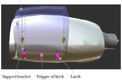
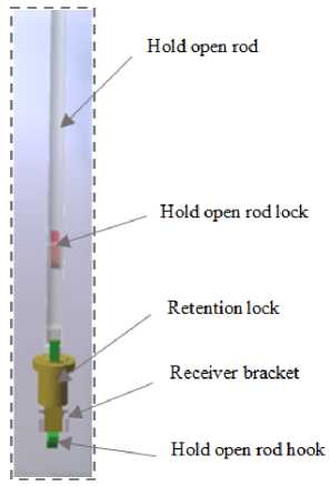
In Stage 2, nine components of the fan cowl door were modelling in Blender. The components, such as fan cowl door, support bracket, trigger of latch and latch are presented in Fig. 3(a). The other components, such as hold open rod, hold open rod lock, retention lock, receiver bracket and hold open rod hook are shown in Fig. 3(b). The fan cowl door and hold open rod are set to transparent to increase the visibility of other components which are placed behind them.
After all the components were modeled, several animations were created to show the AMM procedure for opening the fan cowl door. The AMM procedures are listed below [15]:
-
1. Unlatch the latches of fan cowl door.
-
2. Release the hold open rods from the receiver bracket.
-
3. Elongate the hold open rods and attach them to the support bracket.
There are two hold open rods to be released from the receiver bracket. Therefore, second and third procedures are repeated for opening for another hold open rod. In other words, the sequence of the AMM procedure is 1-23-2-3.
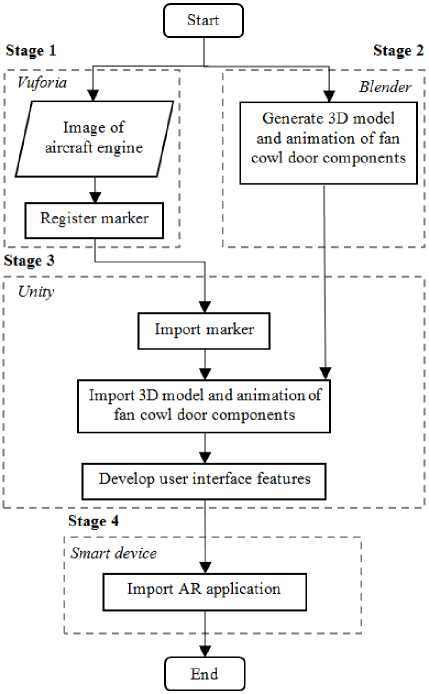
Fig.1. The flowchart of the algorithm of the AR application.
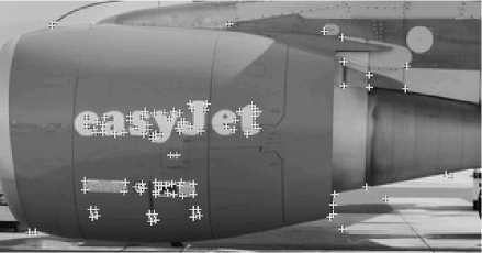
Fig.2. Three-star rated marker
To describe the procedure step by step, detailed step breakdown of each procedure is created. The first procedure is separated into two steps which are pressing the trigger of latch and opening of the latch and lifting the fan cowl door. The second procedure is separated into two steps, such as pulling and holding the retention lock and pulling the hold open rod. The third procedure is divided into three steps which are extending the hold open rod, pulling and holding the retention lock, and attaching the hold open rod hook. Thus, there are a total of 12 steps for fan cowl door opening for the complete sequence of the AMM procedures which are 1-2-3-2-3. Steps 1 to 7 guide on opening of the first hold open rod according to AMM procedures of 1-2-3. Steps 8 to 12 guide on opening of second hold open rod according to AMM procedures of 2-3. Finally, Step 13 is added for lifting of the fan cowl door.
Fan cowl door
(a)
(b)
Fig.3 (a). The components of fan cowl door (b) Enlarged view of the selected region in (a).
Animations were created to give the working instruction of each step. Table 1 shows the text and Graphical user interface (GUI) displayed on the screen, and the input required to trigger animation for pre-step to Step 13. Every animation is accompanied by an arrow to direct the AMT to push, pull, or rotate the relevant component. The AR application starts with pre-step which instructs user to track the marker. The details of Steps 1 to 13 are discussed as follows.
-
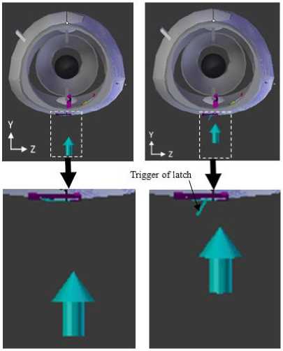
1: User is instructed to press the trigger of latch and open the latch. Fig. 4(a) and Fig. 4(b) show the scene views before and after the animation for Step 1-1. As shown, the arrow is animated to move toward the trigger of latch. At the same time, the trigger of latch rotates counterclockwise in the Y-Z plane. Fig. 5(a) and Fig. 5(b) show the view of the trigger of latch, latch and arrow before and after the animation of Step 1-2. As shown, the straight arrow is replaced by the curved arrow. The curved arrow rotates clockwise in the Y-Z plane below the trigger of latch. The latch rotates clockwise about its end. The animations are repeated for three times for opening of three latches.
Table 1. The Text and GUI Displayed and The Input Required to Trigger Animation
|
Step |
Text displayed on the screen |
GUI displayed on the screen |
GUI to be tapped to trigger animation |
|
Prestep |
Find fan cowl door |
Quit |
No |
|
1 |
Step 1: Unlatch three latches |
Quit, Next and Back |
Marker / Back of Step 2 |
|
2 |
Step 2: Lift the door |
Quit, Next and Back |
Next of step 1 / Back of Step 3 |
|
3 |
Step 3: Pull and hold retention lock of hold open rod |
Quit, Next and Back |
Next of step2 / Back of Step 4 |
|
4 |
Step 4: Pull out the rod |
Quit, Next and Back |
Next of step 3 / Back of Step 5 |
|
5 |
Step 5: Press locker of strut and extent the rod |
Quit, Next and Back |
Next of step 4 / Back of Step 6 |
|
6 |
Step 6: Pull and hold retention lock |
Quit, Next and Back |
Next of step 5 / Back of Step 7 |
|
7 |
Step 7: Attach rod to support bracket |
Quit, Next and Back |
Next of step 6 / Back of Step 8 |
|
8-12 |
Repeating Steps 3-7 |
||
|
13 |
Step 13: Lift door |
Quit, Next and Next of Step Back 12 |
|
-
2: User is instructed to lift the fan cowl door. By referring Fig. 6(a) and Fig. 6(b), the positions of arrow and fan cowl door are changed after animation. Both of them move upward. The hold open rod is visible after the fan cowl door is lifted.
-
3: User is instructed to pull the retention lock by the arrow and retention lock move upward along the hold open rod as shown in Fig. 7(a) and Fig. 7(b).
-
4: User is instructed to pull the hold open rod towards the engine. As shown in Fig. 8(a) and Fig. 8(b), the arrow is animated to move towards the engine. Meanwhile, the hold open rod rotates clockwise about its end near to the hook.
-
5: User is instructed to press the locker of hold open rod and extend the hold open rod. Fig. 9(a) and Fig. 9(b) show the scene view before and after the animation for Step 5-1. As shown in, the arrow is animated to move toward the locker of hold open rod. At the same time, the locker of hold open rod rotates clockwise about its end. Besides, the arrow and hold open rod move downward
along the hold open rod. Fig. 10(a) and Fig. 10(b) show the scene view of the trigger of latch, latch and arrow before and after the animation of Step 5-2. As shown, the arrow and retention lock move downward along the hold open rod.
(a) (b)
Fig.4. The scene views (a) before and (b) after the animation of Step 1-1.
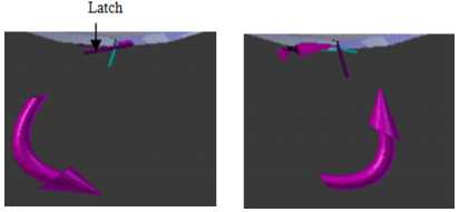
Fig.5. The scene views (a) before and (b) after the animation of Step 1-2.
-
6: User is instructed to pull and hold the retention lock by the animation of the arrow and retention lock move upward
along the hold open rod as shown in Fig. 11(a) and Fig. 11(b).
-
7: User is instructed to attach the hold open rod hook to support bracket. As shown in Fig. 12(a) and Fig. 12(b), the arrow is animated to move towards the engine. At the same time, the hook of hold open rod rotates clockwise about its end.
8-12: Steps 3 to 7 are repeated for opening the second hold open rod.
-
13: User is instructed to lift the door, the arrow and fan cowl door are animated to move upward as shown in Fig. 13(a) and Fig. 13(b).
In Stage 3, the 3D models and animations of fan cowl door components and the marker created in Stage 1 were imported to Unity. After that, the components created were aligned and mapped with the marker. For the development of user interface, such as text and touch buttons as given in Table 1, the canvases were created for each scene. The canvas with two buttons, “Next” and “Back” is assigned as a child of the ImageTarget in Unity. Then, algorithm of the user interface is integrated into Unity. In Stage 4, the developed application is saved as a scene file and imported to the Android smart device.
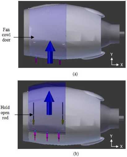
Fig.6. The scene views (a) before and (b) after the animation of Step 2.
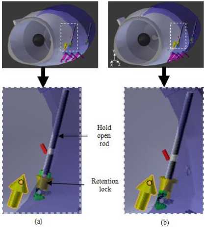
Fig.7. The scene views (a) before and (b) after the animation of Step 3.
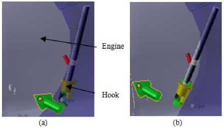
Fig.8. The scene views (a) before and (b) after the animation of Step 4.
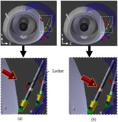
Fig.9. The scene views (a) before and (b) after the animation of Step 5-1.
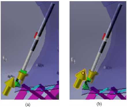
Fig.11. The scene views (a) before and (b) after the animation of Step 6.
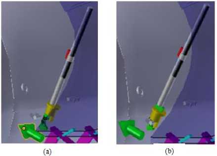
Fig.12. The scene views (a) before and (b) after the animation of Step 7.
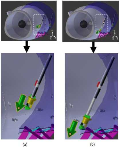
Fig.10. The scene views (a) before and (b) after the animation of Step 5-2.
(a)
(b)
Fig.13. The scene views (a) before and (b) after the animation of Step 13.
-
B. Capability Check of Augmented Reality Application
The capability of tracking the marker based on different camera angle was studied. The camera angle θ is measured between the smart device and the marker surface as shown in Fig. 14. The smart device was placed 0.15 m apart from the marker vertically. Five different angles, such as 30°, 60°, 70°, 80° and 85° are examined.
The second experiment was conducted to check the capability of the application to detect marker based on different vertical distances l , as shown in Fig. 14. With zero camera angle, five distances, such as 0.4 m, 0.6 m, 0.8 m, 1.0 m, and 1.2 m were investigated.
The third experiment was carried out to check the visibilities of the 3D models and animations from different camera angles. at the camera angles investigated including 30°, 60°, 70° and 80°.
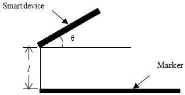
Fig.14. Camera angles, θ of marker.
-
IV. Result and Discussion on the developed Augmented Reality Application
The AR application is developed and is accessed via some steps as listed:
-
1. Touch the AR application icon on the screen of the smart device.
-
2. Position the smart device’s camera to the aircraft engine image until the image is tracked.
-
3. Touch the GUI to trigger different scenes in the application.
Fig. 15 shows a sample of the actual scene seen by the users. The scene gives information about how to lift the fan cowl door. The scene in Fig. 15 is different from those in Fig. 3 to Fig. 13 because of Fig. 3 to Fig. 13 give the scenes in Computer-Aided Design (CAD) environment.
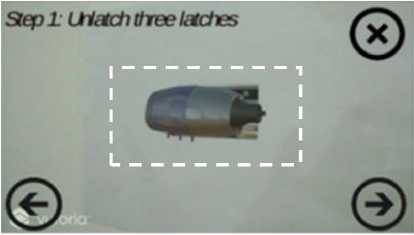
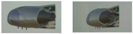
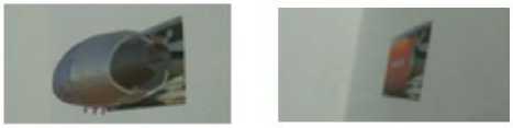
The marker detectability of the AR application was checked for camera angles of 30°, 60°, 70°, 80°, and 85°. The results are presented in Fig. 16(a) to 16(e) where Fig. 16(a) shows the scene view for camera angle of 30°. Fig. 16(b) to Fig. 16(e) show the partial view at the center of the scene for camera angles of 60°, 70°, 80°, and
85°respectively. As shown in Fig. 16(a) to Fig. 16(d), the marker is recognized by the developed AR application for 30°, 60°, 70° and 80° camera angle. The developed AR application fails to recognize the marker for camera angle of 85° in Fig. 16(e). This shows the developed application can track the marker from viewing angles in between 30° - 80°.
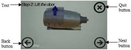
Fig.15. Scene to instruct user to lift the door.
(a)
(b) (c)
(d) (e)
Fig.16. Scene displayed when the smart device is positioned at (a) 30°, (b) 60°, (c) 70°, (d) 80° and (e) 85°, of camera angle.
For marker detectability for different vertical distance l , the smart device capable to track the marker for vertical distance of 0.4 m, 0.6 m, 0.8 m, 1.0 m. Thus, the application is able to detect the marker up to a distance of 1.0 m.
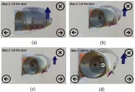
Fig.17. Scene of Step 2 when the smart device is positioned at (a) 30°, (b) 60°, (c) 70° and (d) 80°, of camera angle.
The 3D models and all the step-by-step animations are visible when smart device was positioned at camera angle of 30°, 60°, 70° and 80°. Fig. 17 (a), (b), (c) and (d) give a sample to show the visibilities of the 3D models and animations at 30°, 60°, 70° and 80° respectively based on scene ofStep 2 animations. As seen in the figures, the 3D models of fan cowl door components, text and arrow are visible even the smart phone are placed at different angles of 30°, 60°, 70° and 80°.
-
V. Conclusion
A marker-based AR application with touch user interfaces was successfully developed for aviation maintenance of opening fan cowl door. The maintenance procedures are presented in the form of animation and text. The user can acquire the working instructions of the maintenance manual step by step by viewing the information through the smart device’s screen. The marker can be detected within the camera angle of 30° to 80° and tracking distance of 0.4 m to 1.0 m. The animations displayed in the scenes are visible at camera angle of 30° to 80°. The AR application is able to present AMM procedures and supports user interaction for fan cowl door opening.
References A mobile application of augmented reality for aircraft maintenance of fan cowl door opening
- H. J. Shyur, "A quantitative model for aviation safety risk assessment." Computers & Industrial Engineering 54, no. 1 (2008): 34-44, doi:10.1016/j.cie.2007.06.032.
- M. Janic, “An assessment of risk and safety in civil aviation,” Journal of Air Transport Management, vol. 6, no. 1, 2000, pp. 43-50, doi:10.1016/S0969-6997(99)00021-6.
- W. Rankin, "MEdA investigation process." Boeing Commercial Aero (2007).
- K. A. Latorella and P. V. Prabhu, “A review of human error in aviation maintenance and inspection,” International Journal of Industrial Ergonomics, vol. 26, no. 2, pp. 133-161, 2000, doi:10.1016/S0169-8141(99)00063-3.
- F. De. Crescenzio, M. Fantini, F. Persiani, L. Di Stefano, P. Azzari, and S. Salti, “Augmented reality for aircraft maintenance training and operations support,” IEEE Computer Graphics and Applications, 2011, pp. 96-101, doi:10.1109/MCG.2011.4.
- C. G. Drury and P. Prabhu, “Information requirements of aircraft inspection: framework and analysis,” International journal of human-computer studies, vol. 45, no. 6, pp. 679-695, 1996, doi:10.1006/ijhc.1996.0074.
- A. F. Waruwu, I. P. A. Bayupati, and I. K. G. D. Putra. "Augmented reality mobile application of Balinese Hindu temples: DewataAR." International Journal of Computer Network and Information Security 7, no. 2 (2015): 59, doi:10.5815/ijcnis.2015.02.07.
- J. Sausman, A. Samoylov, S. H. Regli, and M. Hopps, "Effect of eye and body movement on augmented reality in the manufacturing domain." In Mixed and Augmented Reality (ISMAR), 2012 IEEE International Symposium on, pp. 315-316. IEEE, 2012, doi:10.1109/ISMAR.2012.6402591.
- S. J. Henderson and S. K. Feiner, “Augmented reality for maintenance and repair (ARMAR),” Columbia Univ New York Dept of Computer Science, USA, Rep. Jun 2005-Aug 2007, 2007.
- T. Haritos and N. D. Macchiarella, “A mobile application of augmented reality for aerospace maintenance training.” in Digital Avionics Systems Conference, 2005. DASC 2005, Washington, DC, USA, 2005, pp. 5-B, doi:10.1109/DASC.2005.1563376.
- G. Jo, K. J. Oh, I. Ha, K. S. Lee, M. D. Hong, U. Neumann, and S. You. “A Unified Framework for Augmented Reality and Knowledge-Based Systems in Maintaining Aircraft.” In Twenty-Sixth IAAI Conference, 2014.
- S. J. Henderson and S. K. Feiner. "Augmented reality in the psychomotor phase of a procedural task." In 2011 10th IEEE International Symposium on Mixed and Augmented Reality, pp. 191-200. IEEE, 2011.
- K. Conradi, “Report on the accident to Airbus A319-131, GEUOE London Heathrow Airport on 24 May 2013,” Air Accidents Investigation Branch, London, Rep. 1/2015, 2015.
- Flickr. 2014. CFM International CFM56-5B engine of EasyJet A320-214 G-EZWB, Manchester Airport, 9 July 2014. www.flickr.com/ photos/ 29075152 @ N02/ 14794163052.
- Training Manual A319/ A320 / A321, Lufthansa Technical Training., Germany, 1999.
