A model checking-based method of functional test generation for HDL descriptions

Author: Lebedev M.S., Smolov S.A.
Journal: Труды Института системного программирования РАН @trudy-isp-ran
Article in issue: 4 т.28, 2016.
Free access
Automated test generation is a promising direction in hardware verification research area. Functional test generation methods based on models are widespread at the moment. In this paper, a functional test generation method based on model checking is proposed and compared to existing solutions. Automated model extraction from the hardware design’s source code is used. Supported HDLs include VHDL and Verilog. Several kinds of models are used at different steps of the test generation method: guarded action decision diagram (GADD), high-level decision diagram (HLDD) and extended finite-state machine (EFSM). The high-level decision diagram model (which is extracted from the GADD model) is used as a functional model. The extended finite-state machine model is used as a coverage model. The aim of test generation is to cover all the transitions of the extended finite state machine model. Such criterion leads to the high HDL source code coverage. Specifications based on transition and state constraints of the EFSM are extracted for this purpose. Later, the functional model and the specifications are automatically translated into the input format of the nuXmv model checking tool. nuXmv performs model checking and generates counterexamples. These counterexamples are translated to functional tests that can be simulated by the HDL simulator. The proposed method has been implemented as a part of the HDL Retrascope framework. Experiments show that the method can generate shorter tests than the FATE and RETGA methods providing the same or better source code coverage.
Hardware design, functional verification, static analysis, test generation, guarded action, high-level decision diagram, extended finite state machine, model checking
Short address: https://sciup.org/14916375
IDR: 14916375 | DOI: 10.15514/ISPRAS-2016-28(4)-3
Генерация функциональных тестов для HDL-описаний на основе проверки моделей
Разработка методов автоматической генерации тестов составляет перспективное направление в области верификации цифровой аппаратуры. На текущий момент большое распространение имеют методы генерации функциональных тестов на основе моделей. В данной работе представлен метод генерации функциональных тестов на основе проверки моделей и результаты его сравнения с существующими решениями. В методе используется автоматическое извлечение моделей из исходного кода HDL-описания аппаратуры. Поддерживаются языки VHDL и Verilog. Метод генерации тестов включает автоматическое построение моделей следующих типов: решающие диаграммы системы охраняемых действий (Guarded Action Decision Diagram,GADD), высокоуровневые решающие диаграммы (High-Level Decision Diagrams, HLDD) и расширенные конечные автоматы (Extended Finite-State Machines, EFSM). HLDD-модель используется в качестве функциональной модели. Модель EFSM используется в качестве модели покрытия. Целью тестирования является покрытие всех переходов расширенного конечного автомата. Выбор такого критерия позволяет получить высокое покрытие исходного кода HDL-описания. Из EFSM-модели извлекаются спецификации, основанные на ограничениях на переходы и состояния. Затем спецификации и функциональная модель автоматически транслируются во входной формат инструмента проверки моделей nuXmv. Инструмент выполняет проверку модели и строит контрпримеры. Контрпримеры транслируются в функциональные тесты, которые могут быть исполнены с помощью HDL-симулятора. Предлагаемый метод был реализован программно в инструменте HDL Rertrascope. Результаты экспериментов показывают, что метод генерирует более короткие тесты, чем методы FATE и RETGA, при обеспечении такого же или лучшего покрытия исходного кода.
Text of the scientific article A model checking-based method of functional test generation for HDL descriptions
Functional verification is an expensive and time-consuming stage of hardware design process [1]. Due to hardware designs increasing complexity, automated test generation seems to be important and challenging. To avoid design complexity, automated verification methods often utilize mathematical abstractions of system properties and behavior, so-called models. Models can be created manually or automatically extracted from the system’s source code. Automated verification methods based on model extraction from the HDL (Hardware Description Language - a collective name for several languages described below) source code are considered in this paper. Models can be based on the following formal descriptions: finite-state machines, decision diagrams, Petri nets [2], etc.
Model checking [3] is an approach to set up the correspondence between the model of the system and formal conditions (specifications). For every specification a model checker tries to produce a counterexample - an input stimuli sequence that leads the system into a specification-contradicting state. Counterexample construction is often used for functional test generation purposes.
Proof of equivalence of a model and the corresponding system is an important issue when model checking is used for hardware verification. There is no need in such proof when the model is automatically extracted from the system’s source code and translated into the model checker’s format.
A method of functional test generation for hardware is proposed in this paper. It is based on automatic extraction of High-Level Decision Diagrams (HLDD) [4] from the system’s source code. Synthesizable sets ofVHDL [5] and Verilog [6] HDLs are supported. Extracted models are then automatically translated into SMV (Symbolic Model Verifier) language supported by the nuXmv [7] model checker. Extended Finite State Machine (EFSM) transition constraints are used as specifications for model checking. EFSM model is also extracted from the system’s source code. Counterexamples built by the nuXmv model checker are then translated into an HDL testbench which can be simulated by an HDL simulator.
The rest of the paper is organized as follows. Section 2 contains a review of functional test generation methods based on model extraction from the HDL source code. In Section 3 basic definitions are given. Section 4 contains HLDD construction and test generation methods. Section 5 is dedicated to the experimental results. Section 6 concludes the paper.
2. Related works
The idea of model extraction from the HDL source code and following test generation is not new. A prototype of CV tool for VHDL description model checking is presented in [8]. The tool’s execution process consists of five stages. On the first stage, a VHDL description is parsed and an internal representation is constructed. A Binary Decision Diagram (BDD) based model is built on the second stage. On the third stage a CTL-based specification is parsed. The specification language syntax is described in the paper. On the fourth stage the specification parsing result and the BDD-based model are passed to the CBMC [9] model checker. On the final stage, the model checker output is translated into tests that can be executed by the HDL simulator. It is stated that BDD-based model size plays the key role in the model checking process. Model size reduction heuristics usage is suggested to avoid state space explosion but no heuristics are offered in the paper.
In [10], extraction of the EFSM model and generation of tests that cover all the model transitions are described (so-called FATE method). This method assumes that the user provides additional information for the tool about signal semantics (for example, which of the signals encodes state). The EFSM extraction process contains several stages of transition structure simplification (embedded conditions elimination, compatible transitions union, dataflow dependency analysis). The test generation method is based on the state graph traversal through random walk and backjumping techniques.
In [11] an improved modification of method [10] is proposed. Optimizations described concern path reachability (weakest precondition [12] is used instead of the approximate approach) and test filtering tasks. A new functional test generation method called RETGA is also proposed in [11]. This method is based on the algorithm [13] for automated EFSM model extraction from HDL descriptions. The algorithm does not require additional information about signals\variables semantics; for state and clock-like variable detection it uses heuristics based on dataflow dependencies. Experiments have shown that RETGA method produces shorter tests with higher HDL code coverage than FATE and even improved FATE do.
It should be noted, that state graph traversal techniques (that FATE and RETGA methods use) do not guarantee coverage of all the EFSM model transitions. One of the problems concerns counter [11] variables that are defined in transition loops and used in transition guards, so an EFSM simulation engine needs to recognize at which value of the counter it is going to finish the loop execution.
3. Basic definitions
Suppose that all models described below run in discrete time that implies clock presence. Clock C is a set of events {с/,.. ,,сЦ where an event c = (signal, edge} is a pair, consisting of a one-bit signal (so-called clock pulse) and a type of registration called edge (i.e. positive edge when signal changes its value from 0 to 1 and negative edge otherwise).
Let Ebe a set of variables. A valuation is a function that associates a variable v е V with a value [v] from the corresponding domain. Let Dontybe a set of all valuations of E. A guard is a Boolean function defined on valuations (Domy—> (true, false}). An action is a transform of valuations (Domy—> Domy). A pair 7 —> 5, where 7 is a guard and § is an action, is called a guarded action (GA). It is implied that there is a description of every function in some HDL-like language (thus, we can reason about not only semantics, but syntax).
Let guarded actions be synchronized [14], if each GA is associated with a clock. A system {{C^, y(,) -><5 ’'’)!, 1/ of synchronized guarded actions can be represented by an oriented acyclic graph G = (N, E, Q called Guarded Actions Decision Diagram (GADD). Here A is a set of graph nodes, E is a set of graph edges, and C is a clock.
N contains two non-intersecting subsets: a set N, of non-terminal nodes n. that are marked by expressions pnsf a set N( of terminal nodes nt that are marked by actions 5fuY Graph edges can start from non-terminal nodes only and finish either in terminal or in non-terminal nodes. Edges е e fare marked by sets Valp, n) of accepted values ү(п) (here edge e is an outgoing edge for the node n, е e Out(n)). The node n e Ns can have no more than one ea e Ou Un) that is marked by default keyword - it means that for this path in G an expression y(n) equals to a value that does not belong to any marking sets of the other edges outgoing from the node n. Supposing that the GADD contains exactly one root node nroot (the node without incoming edges, In(nrooi) = Д), a set of paths from the root node to all the terminal nodes produces a system of synchronized guarded actions. For example, the Ith path, including nPf./n^P nodes and elf..., em.p edges (np = nroot, n„P e Nt, ер e OutfnP) о In(nu+P), и = l,...,m-iy defines a guarded action with pP...pm.P (pP = AND^lnf == q), r = l,...,m-l, q e Valpr, nP conjunction as a guard and 5fimP as an action. The guarded action clock is a subset of the GADD clock.
In [4] a definition of a high-level decision diagram (HLDD) is given and is shown that every variable of an HDL description can be represented by a function v =/(v/,...,v„) =RV) in terms of HLDD Hv. Let Z(v) be a finite set of all possible values of a variable v е V. A High-Level Decision Diagram for v is an oriented acyclic graph H, = IM, Г, V) where M is a set of nodes, and /Isa mapping M —> 2м. Let Дт) be a set of subsequent nodes of the node m е M and /fm) be a set of preceding nodes of the node m. X node mo of the graph H, is said to be initial if the set of its preceding nodes is empty: Fpmo) = 0. M consists of two non-intersecting subsets: Mn for non-terminal nodes and M, for terminal nodes. All the non-terminal nodes mc e Mn are marked by variables v(mc) е V and meet the following condition: 2 < I Дтс)| < |Z(v(mc))|. This means that m. has at least two subsequent nodes but not more than the number of possible values of v(mcy All the terminal nodes mt e M, are marked by functions vlmkpffVkY MVk) е F (Vk^V). Usually some of these functions are trivial and equal either to variables Vk e Lor to constants. All the edges are marked by sets of accepted values of variables in the same manner as in the GADD definition; the semantics of the default edges is also similar.
On every tick of the clock, the HLDD Hv assigns a value to the target variable v through an activation procedure. Starting from the initial node mo it calculates values of the variables which mark non-terminal nodes. For a value e of the variable v(mc), е e Z(v(mc)), the corresponding edge from the node mc е M to the subsequent node me е Дтс) is activated. A vector И of variable values activates the path Қто, пр from mo to the terminal node mk marked by the function УРР that determines the value of the target variable v.
4. HLDD model construction and test generation method
The proposed test generation method consists of the following steps:
-
• HDL (VHDL/Verilog) description parsing and GADD model construction.
-
• HLDD model construction using the GADD model.
-
• HLDD model and specification translation into the nuXmv model checker input language (SMV model) [16].
-
• SMV model checking by the nuXmv model checker and translation of counterexamples into HDL tests.
-
4.1. HLDD model construction
The first step has been implemented in [13] so we will start from the second step. Note that all the actions, which mark the terminal nodes of the GADD model, are represented in the static single assignment (SSA) [15] form.
GADD and HLDD models preserve the module structure of the original HDL description. Every HDL description process is represented by a single GADD. The GADD G = (N, Е, C) is used as a basis for HLDD construction for every non-input variable of the process. HLDD construction algorithm pseudo code is listed below:
proto = new, for node e N do hldd node = transform nodeinode).
proto. add(hlddnode);
end copy_edgesi,E, proto);
hldd.add_m issingterm inals();
hldd. transform identical assigns));
end
At the first step the HLDD prototype proto is created. GADD nodes are transformed into HLDD nodes with the help of the transform node method and added to the prototype. Terminal GADD nodes nt e N( are transformed into terminal HLDD nodes mk e Mt. Every terminal node nt marked by multiple assignment action 5(nt) is transformed into a sequence of nodes. Every node in this sequence is marked by a corresponding single assignment Ok. Every terminal HLDD node is marked by a target variable Vk (which is the left-hand side of at) and a function ffVk) (which is the righthand side of ak).
Non-terminal GADD nodes n e Ns are transformed into non-terminal HLDD nodes m. e Mn. Guard у which marks the node n. is replaced by a new variable guard(mc) which marks the node mc. The new HLDD that contains a single terminal node marked by у is created for this variable (create variableJromswitch method). GADD edges are transformed into HLDD edges by the copy edges method. The corresponding values are not changed.
Then for every non-input variable v the HLDD hldd is created which is actually a modified copy of proto. The keep assigns method removes from Mt the terminal nodes which are not marked by v. After that the add missing terminals method adds new terminal nodes marked by f(v) = v to the edges which lack the subsequent terminal nodes. This means that the value of v does not change if any path to such node is activated. The transform identical assigns method searches for such nonterminal nodes mc whose reachable terminal nodes are marked by the same function fk(vk), and replaces m. and its reachable subgraph with the only terminal node marked ЬуЛМ
Consider an example of the HLDD model construction for a simple VHDL description. This description contains a single module and a single process. The module interface consists of input variables elk, rst, x, у and an output variable res (all of 1 -bit size). The process contains two internal variables: a 1 -bit size vector ent and an integer state (that can be assigned either 0 or 1). The source code of the process is listed below:
process (elk, rst, x, y)
variable ent: std_logic;
variable state: integer range 0 to 1;
begin if (rst = ‘1’) then ent := ‘O’;
state := 0;
elsif (elk = ‘1’) then if (state = 1) then ent := x or y; state := 0;
elsif (state = 0) then ent : = x and y; state := 1;
end if;
res <= ent;
end if;
end process;
0 shows the GADD model of the process. Non-terminal nodes of the GADD are shown as diamonds and correspond to branch expressions. Terminal nodes are shown as rectangles and correspond to basic blocks. Outgoing edges from the non-terminal nodes are marked by possible values of the branch expressions. Note that the default edge on 0 is unreachable because the state variable can only take the value of 0 or 1. The clock of the GADD is formed by events of elk, rst, x and у signals.
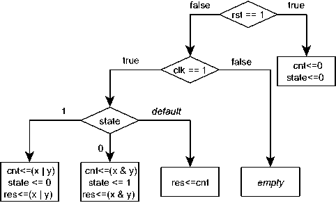
Fig. 1. GADD model.
0 shows the HLDD prototype. Expressions, which mark the non-terminal nodes, are replaced by guardO, guardl, guard2 variables.
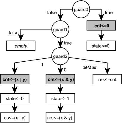
Fig. 2. HLDD prototype.
Consider the HLDD construction for the ent variable. Terminal nodes marked by ent are highlighted in grey on 0. Terminal nodes, which are not marked by this variable, are removed. New terminal nodes marked by ent are added to the free non-terminal node edges (this means that the value of ent does not change on these paths). The final HLDD is represented on 0. Similar diagrams are constructed for the other non-input variables of the HDL description (in our example those are: state and resY
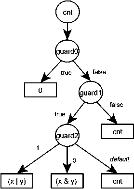
Fig. 3. HLDD of a ent variable.
-
4.2. SMV model construction and checking
The constructed HLDD model is translated into an SMV language description. Hardware design module structure is preserved. Any variable constraints (like the range of possible values that is specified for the state variable) and their initial values described in the HDL description are added to the SMV model.
Specification construction is based on the EFSM model extracted from the same HDL description. Formal definition of the EFSM model and its extraction algorithm from an HDL description are presented in [13]. Here we provide only the informal definition. Extended finite-state machine is a special case of an ordinary finite-state machine (FSM). It contains sets of inputs, outputs and internal variables. EFSM transitions are marked by guard expressions, which depend on input and internal variable values, and by actions that can change internal and output variable values. A transition can be enabled only if its guard becomes true. When a transition is enabled, its action is executed. Specifications used by the proposed method are represented as negations of the EFSM transition guards. Negation is used to make the model checker build a counterexample - a sequence of data states and input stimuli that contradicts the specification (and thus satisfies the corresponding guard).
The nuXmv model checker checks the SMV model along with the specifications. Output counterexamples are translated into a test set aimed at covering reachable EFSM transitions.
Below you can see the HLDD-to-SMV translation result for the
ent
and
guardO
variables. NuXmv-compatible SMV language format is used. The description consists of the variable declaration section (VAR) and the assignment section (ASSIGN). The
init
construct defines the initial value of a variable. The
next
construct defines the value of a variable in the next model state. The assignment (“:=”) defines the value of a variable in the current model state. Numeric values in the example are of bit vector type and are represented by “0
VAR ent: wordfl];
guardO : boolean;
ASSIGN iroXcn0 := 0dl_0;
ASSIGN
/lext(cnt) := case
(guardO = TRUE): 0dl_0;
(guardO = FALSE):
case
(guard 1 = TRUE):
case
(guard2 = 0sd32_l): (x | y);
(guard2 = 0sd32_0): (x & y);
TRUE : ent;
esac;
(guardl = FALSE) : ent;
esac;
esac;
guardO := (rst = 0dl_l);
guardl := (elk = 0dl_l);
guard2 := state
The example of an SMV specification is listed next:
LTLSPEC ! F ((state = 0sd32_0) & (elk = Odl_l) & !(rst = Odl_l));
EFSM transition reachability condition consists of the state variable constraint (which determines the source state of the transition) and the guard condition depending on the elk and rst variables.
The nuXmv model checker generates the following counterexample for this specification:
Trace Type: Counterexample
-
-> State: 1.1 <-
- SAMPLE.process.state = 0sd32_0
SAMPLE.process.guard2 = 0sd32_0
elk = 0udl_0
у = 0udl_0
x = 0udl_0
rst = 0udl_0
-> State: 1.2 <-
- SAMPLE.process.guardl = TRUE 5. Experimental results
clk = 0udl 1
The first state shows the initial values assigned to the variables. The second state shows only the values that have changed. We can see that the second state contradicts the given SMV specification: elk is equal to 1, while the rst and state variables are equal to 0.
The proposed test generation method was implemented as a part of the HDL Retrascope 0.2.1 software tool [17]. Java language was used for development along with the Fortress formulae manipulation library [18]. Some HDL descriptions from the ITC’99 benchmark [19] were used for testing of the proposed approach.
The nuXmv model checker supports both symbolic model checking and bounded model checking [21] methods. In some cases, symbolic model checking needed too much time and computer resources because of the state explosion (for example, B04, BIO and Bll designs). Bounded model checking could manage this problem by exploring the model state space only up to some bound. However, bound value affects the model checking results (not all the counterexamples may be obtained at the specified bound). Therefore, in some cases the bound size was iteratively increased in order to get all possible counterexamples.
Generated tests were simulated by the QuestaSim HDL simulator [20]. Test properties (length and source code coverage) were compared to existing test generation methods like FATE [10], RETGA [11] (these methods are based on EFSM model extraction from the HDL descriptions and are targeted at covering the EFSM model transitions) and random test generation.
Ocontains information about the ITC’99 designs that were used for test generation: their source code size and the corresponding SMV model size (without specifications). Size is given in lines of code.
Table 1. HDL description and SMV model size
|
Design |
HDL |
SMV |
|
B01 |
102 |
207 |
|
B02 |
70 |
143 |
|
B03 |
134 |
637 |
|
B04 |
101 |
809 |
|
B06 |
127 |
442 |
|
B07 |
92 |
370 |
|
B08 |
88 |
315 |
|
B09 |
100 |
263 |
|
B10 |
167 |
755 |
|
B11 |
118 |
368 |
Table 3. Source code statement coverage
|
Design |
FATE |
RETGA |
SMV |
Random |
|
B01 |
97,14% |
100% |
100% |
100% |
|
B02 |
100% |
100% |
100% |
100% |
|
B03 |
- |
- |
100% |
100% |
|
B04 |
100% |
100% |
100% |
100% |
|
B06 |
100% |
100% |
100% |
100% |
|
B07 |
93,93% |
93,93% |
93,93% |
84,85% |
|
B08 |
81,81% |
100% |
100% |
90,91% |
|
B09 |
35,29% |
100% |
100% |
61,77% |
|
B10 |
95,94% |
100% |
100% |
97,29% |
|
B11 |
69,23% |
94,87% |
94,87% |
87,18% |
0contains the test length information. Test length is given in clock cycles. The length of tests generated by the random generation method corresponds to the point when the test coverage growth stops (maximum length was chosen as 1000000 clock cycles). The sign “-” means that the corresponding method failed to generate tests for the corresponding HDL design.
Table 2. Test length
|
Design |
FATE |
RETGA |
SMV |
Random |
|
B01 |
115 |
49 |
69 |
300 |
|
B02 |
62 |
33 |
47 |
80 |
|
B03 |
- |
- |
504 |
2000 |
|
B04 |
104 |
36 |
67 |
200 |
|
B06 |
198 |
76 |
88 |
700 |
|
B07 |
246 |
166 |
249 |
1000 |
|
B08 |
31 |
52 |
31 |
1000000 |
|
B09 |
19 |
231 |
84 |
1000000 |
|
B10 |
173 |
135 |
134 |
650000 |
|
B11 |
101 |
721 |
194 |
1000000 |
In 5 of 10 cases tests generated by the proposed method are shorter than tests generated by the FATE method and longer that RETGA tests. Either the rest tests are of comparable length with the leader (RETGA), or tests generated by the FATE method provide lower coverage. Definitive conclusion about the advantages or disadvantages of the proposed method in comparison with the RETGA method cannot be made using the selected HDL description set.
Notice that unlike the FATE and RETGA methods the proposed method is not based on EFSM traversal. So it was able to generate the test for B03 design in contrast to those methods (EFSM extracted from this design is too complex for traversal).
0shows the HDL source code statement coverage in comparison to the FATE, RETGA and random generation methods.
0shows the HDL source code branch coverage in comparison to the FATE, RETGA and random generation methods.
Table 4. Source code branch coverage
|
Design |
FATE |
RETGA |
SMV |
Random |
|
B01 |
96,15% |
100% |
100% |
100% |
|
B02 |
100% |
100% |
100% |
100% |
|
B03 |
- |
- |
100% |
100% |
|
B04 |
100% |
100% |
100% |
100% |
|
B06 |
100% |
100% |
100% |
100% |
|
B07 |
94,73% |
94,73% |
94,73% |
73,69% |
|
B08 |
76,92% |
100% |
100% |
84,62% |
|
B09 |
35,71% |
100% |
100% |
57,15% |
|
B10 |
90,47% |
100% |
100% |
97,61% |
|
B11 |
71,87% |
96,87% |
96,87% |
90,63% |
The proposed method achieved the same code coverage as the RETGA method at the specified set of HDL descriptions. B07 and B11 HDL description coverage is less than 100% because of the unreachable code in these designs.
6. Conclusion and future work
The functional test generation method based on automated HLDD model extraction and checking with nuXmv is presented in this paper. The main advantage of this method is its flexibility in choosing a test target (through using different kinds of specifications). EFSM transition coverage is presented for comparison to the other test generation methods (FATE, RETGA). Any other specifications can be formulated and checked in order to get a test aimed at covering the corresponding property of a model. The presented implementation of the proposed approach does not produce shorter tests than existing approaches on the chosen hardware design set. Simple optimizations (like test filtering) can be helpful and are going to be implemented in the nearest future.
Future work is focused on applying the method to more complex hardware designs (including Verilog-based). In this case complexity is defined by the number of execution paths in processes and the number of processes and modules in an HDL description. Process decomposition using dataflow analysis methods and predicate abstraction [22] test generation methods are under research now.
Acknowledgment
References A model checking-based method of functional test generation for HDL descriptions
- J. Bergeron. Writing Testbenches: Functional Verification of HDL Models. Springer, 2003. 478 p.
- V.G. Lazarev, E.I. Piil'. Control automata synthesis. Energoatomizdat, Moscow, 1989. 328 p..
- E.M. Clarke, O. Grumberg, and D.A. Peled. Model Checking. MIT Press, Cambridge, 2000. 314 p.
- R.J. Ubar, J. Raik, A. Jutman, M. Jenihhin. Diagnostic modeling of digital systems with multi-level decision diagrams. Design and Test Technology for Dependable Systems-on-Chip, 2011. pp. 92-118.
- IEEE Standard VHDL Language Reference Manual. IEEE Std 1076-2008 (Revision of IEEE Std 1076-2002), 2009. pp.c1-626.
- IEEE Standard for Verilog Hardware Description Language. IEEE Std 1364-2005 (Revision of IEEE Std 1364-2001), 2006. pp.0_1-560.
- D. Cavada, A. Cimatti, M. Dorigatti, A. Griggio, A. Mariotti, A. Micheli, S. Mover, M. Roveri, S. Tonetta. The nuXmv symbolic model checker. Proceedings of the 16th International Conference on Computer Aided Verification (CAV), 2014, № 8559. pp. 334-342.
- D. Deharbe, S. Shankar, E.M. Clarke. Model checking VHDL with CV. Proceedings of the Second International Conference on Formal Methods in Computer-Aided Design (FMCAD), 1998. pp. 508-514.
- CBMC model checker. Available at: http://www.cprover.org/cbmc/
- G. Guglielmo, L. Guglielmo, F. Fummi, G. Pravadelli. Efficient generation of stimuli for functional verification by backjumping across extended FSMs. Journal of Electronic Functional Testing: Theory and Application, 2011, № 27(2). pp. 137-162.
- I. Melnichenko, A. Kamkin, S. Smolov. An extended finite state machine-based approach to code coverage-directed test generation for hardware designs. Trudy ISP RAN/Proc. ISP RAS, 2015, vol. 27, issue 3,. pp. 161-182 DOI: 10.15514/ISPRAS-2015-27(3)-12
- E. Dijkstra. A Discipline of Programming. Prentice Hall, 1976. 217 p.
- S. Smolov, A. Kamkin. A method of extended finite state machines construction from HDL descriptions based on static analysis of source code. Nauchno-tehnicheskie vedomosti Sankt-Peterburgskogo gosudarstvennogo politehnicheskogo universiteta. Informatika. Telekommunikacii. Upravlenie. , № 1(212), 2015. pp. 60-73.
- J. Brandt, M. Gemünde, K. Schneider, S. Shukla, J.-P. Talpin. Integrating system descriptions by clocked guarded actions. Forum on Design Languages, 2011. pp. 1-8.
- R. Cytron, J. Ferrante, B.K. Rosen, M.N. Wegman, F.K. Zadeck. Efficiently computing static single assignment form and the control dependence graph. ACM Transactions on Programming Languages and Systems, № 13(4), 1991. pp. 451-490.
- M. Bozzano, R. Cavada, A. Cimatti, M. Dorigatti, A. Griggio, A. Mariotti, A. Micheli, S. Mover, M. Roveri, S. Tonetta. NuXmv 1.0 User Manual. 2014. pp. 7-44. Available at: https://es-static.fbk.eu/tools/nuxmv/index.php?n=Documentation.Home.
- HDL Retrascope toolkit. Available at: http://forge.ispras.ru/projects/retrascope.
- Fortress library. Available at: http://forge.ispras.ru/projects/solver-api.
- ITC’99 benchmark. Available at: http://www.cad.polito.it/tools/itc99.html.
- QuestaSim simulator. Available at: https://www.mentor.com/products/fv/questa/.
- E. Clarke, A. Biere, R. Raimi, Y. Zhu. Bounded model checking using satisfiability solving. Formal Methods in System Design, 2001, vol. 19, issue 1, pp. 7-34.
- E. Clarke, M. Talupur, H. Veith, D. Wang. SAT based predicate abstraction for hardware verification. Lecture Notes in Computer Science, 2004, vol. 2919, pp. 78-92.
