A New approach for the numerical assessment of failure of the composite dovetail joint under tensile loading

Author: Guseinov K.A., Kudryavtsev O.A., Sapozhnikov S.B.
Article in issue: 1, 2025.
Free access
This paper proposes and tests a new approach to assessing stress-strain states and determining failure regions of thick-walled tapered composite elements. The mesostructure features of composites, such as ply drops and resin pockets, are not explicitly considered in this approach. The constitutive model based on the multiphase finite element approach was extended to describe the three-dimensional stress-strain state. The model consisted of orthotropic linear-elastic and isotropic elastic-plastic sub-elements which simulate the properties of the fibres and matrix, respectively. The assumption of independence of the shear curve from the type of stress state was adopted to describe the nonlinear deformation response in the model. The calibration of the interlaminar nonlinear response of the constitutive model was performed using the test results of V-notched specimens under combined loading. Then, the verified model was used to determine the delamination load of the dovetail specimens. The delamination load of the dovetail specimens was estimated with the Nouthwestern (NU-Daniel) and the Hashin failure criteria. Finite element analysis of the influence of interlaminar strength and taper angle on the failure load of the dovetail specimens was performed. Based on the results obtained, we proposed the method for determining the rational parameters of the dovetail specimen. It was shown that the new approach could be effective for strength assessment and nonlinear behaviour analysis of tapered thick-walled composite structures at interlaminar shear strains up to 6%.
Fibre-reinforced plastic, numerical simulation, combined loading, non-linear behaviour, interlaminar strength, dovetail joint, fibre-reinforced plastic, numerical simulation, combined loading, non-linear behaviour, interlaminar strength, dovetail joint
Short address: https://sciup.org/146283080
IDR: 146283080 | UDC: 629.7.036.34, 539.419 | DOI: 10.15593/perm.mech/2025.1.07
Новый подход для численной оценки разрушения композитного замкового соединения «ласточкин хвост» при растягивающей нагрузке
Предложен и апробирован новый подход к оценке напряженно-деформированного состояния и определению областей разрушения толстостенных клиновидных композитных элементов. Подход не предполагает рассмотрение в явном виде таких особенностей мезоструктуры, как обрывы слоев и смоляные карманы. Структурная модель полимерного композитного материала, основанная на мультифазном конечно-элементном подходе, была расширена для описания объемного напряженно-деформированного состояния. Модель состояла из ортотропных линейноупругих и изотропных упругопластичных подэлементов, моделирующих свойства волокон и матрицы соответственно. При описании нелинейного отклика в модели было принято предположение о независимости кривой сдвига от вида напряженно-деформированного состояния. Калибровка межслойного нелинейного отклика структурной модели была выполнена с использованием результатов испытаний образцов с V-образным надрезом при комбинированном нагружении. Затем верифицированная модель использовалась для определения нагрузки расслоения образцов типа «ласточкин хвост». Нагрузку расслоения образцов типа «ласточкин хвост» оценивали по критериям разрушения Дэниела и Хашина: выполнены расчетные исследования для оценки влияния межслойной прочности и угла клина на нагрузку разрушения образцов. На основе полученных результатов была предложена методика определения рациональных параметров замкового соединения типа «ласточкин хвост». Установлено, что предложенный подход может быть эффективен для оценки прочности и анализа нелинейного поведения клиновидных толстостенных композитных конструкций при межслойных сдвиговых деформациях до 6 %.
Text of the scientific article A New approach for the numerical assessment of failure of the composite dovetail joint under tensile loading
ВЕСТНИК ПНИПУ. МЕХАНИКА № 1, 2025PNRPU MECHANICS BULLETIN
The carbon fibre-reinforced plastics (CFRP) are considered to be an alternative to metals in elements of new generation aircraft, where weight is one of the critical parameters. Due to significant progress in manufacturing technologies, significant number of load-bearing elements are currently made of composites. In particular, wide-chord fan blades of foreign engines GEnx from General Electric, Rolls-Royce Advance and UltraFan families are made of CFRP [1]. This significantly reduces the weight of the blades and reduces the inertial and dynamic loads transmitted to other engine elements. Currently, composite materials are also widely used in the design of the fan of Russian aircraft engines PD-14 and PD-35 [2].
Dovetail joint is most often used to connect wide-chord fan blades with an engine rotor [3]. The composite dovetail joint is a thick-walled multilayer structure that is subjected to a complex multiaxial loading during operation. The composite dovetail joint may include various manufacturing defects, such as ply drops, warped layers, and resin pockets [4]. Due to these structural inhomogeneities and low interlaminar strength, tapered composite elements are prone to delamination [5]. At the same time, experimental data have shown that the through-thickness compression effect can significantly increase the interlaminar shear strength [6]. The combination of loads (transverse compression and interlaminar shear) leads to a complex nonlinear response, which is largely determined not by the brittle elastic fibre, but by the polymer matrix [6]. Thus, the assessment of the strength of a dovetail joint is a complex scientific and technical problem. A large number of computational and experimental studies are required to solve it [7].
There are two general approaches to predict the delamination load and the delamination growth. They are the strength of materials approach and the strain-energy-release-rate approach. According to the strength of materials approach, local stresses or strains are compared to the allowable material strength. Various failure criteria are used, for example, the maximum stress criterion, the NU-Daniel criteria [8; 9], Christensen [10], Puck [11], Mohr-Coulomb [12], Hashin [13], etc. [14]. The criterion approach of maximum stresses has become widespread in engineering practice for solving this kind of problems [12–15] due to its simplicity. In [15; 20–21], rational reinforcement schemes were selected for mesoscale modelling of thick-walled composite elements. The authors did not explicitly take into account defects such as ply drops and resin pockets in these finite element models. In [21], a two-fold safety factor was obtained using the maximum stress criterion for the outlet guide vane under operating loads. In [22], the experimental results of the outlet guide vane tests under different loading types were compared with the numerical results. It was concluded that the numerical method [21] predicted a reliable assessment of the mechanical state of the composite vane. In [20], the analysis of the strength of the composite frame using the maximum stress criterion demonstrated a difference between the numerical and experimental failure load of 8 %. However, the assessment of the strength using the maximum stress criterion under combined transverse compression/shear predicts a very conservative failure load [23]. The researchers [23] have shown that the NU-Daniel failure criterion predicts a higher delamination load, since the criterion considers the effect of through-thickness compression in the taper part of the dovetail joint. In this case, it is necessary to use, for example, the Hashin criterion [13], which considers the effect of tensile transverse stresses on the interlaminar strength for an adequate assessment of the strength in the thin part. It should be noted that the delamination load was determined without taking into account the actual nonlinear behaviour characteristic of thick-walled composites in the numerical models [15–23].
The alternative strain-energy-release-rate approach is based on fracture mechanics. It is used to predict the delamination growth. The laminate is assumed to fail when the available strain energy of a delamination crack in a ply interface exceeds the critical strain energy release rate for the material. Most researchers [4; 24–29] have predicted the delamination growth in tapered composite elements using virtual crack-closure technique (VCCT) or cohesive zone model (СZM). However, the authors considered the through-thickness compression effect only in some studies [4, 29]. In these studies, high-fidelity finite element simulation was used to describe the layered mesostructure of the composite. The finite element models included ply drops and resin pockets explicitly. Cohesive elements were used to analyse delamination in these models. Unfortunately, there is uncertainty in the parameters of the cohesive element adhesion strength [30-32] and the coefficient of the through-thickness compression effect [33–34] for such models. These discrepancies can lead to an error in determining the delamination region, while the peak delamination load will be significantly underestimated [4]. The researchers [4; 29] have shown that the parameters of cohesive contacts largely determine the failure type and the failure force of severely tapered specimens. It was shown that a good correlation with the experiment can be achieved by varying the parameters of cohesive pairs within the limits known in the literature. In addition, the boundary conditions introduce significant uncertainty into the calculation results. In [4], the authors assessed the effect of the friction coefficient between the dovetail specimen and the disk on the ultimate failure load. Increasing the friction coefficient from 0.1 to 0.3 leads to the change in the failure load by 20 %. It is worth noting that the matrix properties provided by the manufacturer are used when simulating resin pockets in these high-fidelity models. However, authors in [35] showed that the actual in-situ properties of the resin pocket differ significantly from those of the epoxy resin obtained on standard specimens.
The disadvantages of the high-fidelity finite element models combined with the high complexity of their preparation and the duration of calculations make them too difficult for practical engineering calculations of real structures. This is especially critical for the initial design stages when engineers need to select rational reinforcement schemes and assess their impact on the strength and stiffness of the entire structure. For such tasks, it is advisable to develop low-parameter numerical models using the strength approach that considers the features of nonlinear deformation and failure inherent in tapered thick-walled composite elements.
To describe the nonlinear response of composites, various deformation models, based on the approaches of nonlinear elasticity, progressive damage accumulation and elastoplasticity were developed [36]. The significant number of studies [37–43] are related to the description of the in-plane nonlinear response of composites. The algorithm for describing the interlaminar nonlinear response was presented in the papers [44–45]. The researches [44] developed a low-parameter constitutive model in ABAQUS VUMAT for describing the interlaminar nonlinear response of unidirectional glass-and carbon-fibre reinforced plastics. It was shown that the nonlinear response can be approximated by the Ramberg-Os-good power law under pure shear. Similarly, the interlaminar nonlinear response was described in the papers [4; 29] when assessing the strength of tapered thick-walled composite elements. In these studies, the parameters of the approximation of the nonlinear response were determined from the pure shear deformation curves. However, the interlaminar strength and nonlinear response of thick-walled composites under combined loading differ significantly from those under pure shear [6].
The multiphase finite element (mFEA) approach [46] demonstrated good predictive capabilities of the in-plane nonlinear response fabric composites under combined loading [47]. A small number of identifiable parameters makes this model attractive for practical calculations of large structures. In this study, the mFEA approach was modified and expanded to describe the fabric composite interlaminar nonlinear response under combined loading. Model elastic parameters were identified based on standard tensile, compression, and shear test methods. The interlaminar nonlinear response was calibrated based on the test results of V-notched specimens under combined loading. Finally, numerical calculations were performed to assess the static strength of the dovetail joint. The influence of such factors as interlaminar strength and taper angle of the dovetail specimen on the failure load was also studied.
1. Modified mFEA approach
The constitutive model considered in this work is based on previously described mFEA approach [46]. Each volume element is represented as a set of sub-elements with different properties connected by common nodes. In this case, overall deformations of the sub-elements are the same. In accordance with the structure of the material, the model is built from two types of sub-elements: brittle linearly elastic (up to failure) element corresponding to the reinforcing fibres, and elasticplastic one that simulates the properties of some "equivalent" polymer matrix (Fig. 1). The sub-elements are described by well-known material models available in the ANSYS material library.
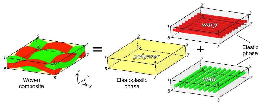
Fig. 1. Representation of mesostructure of woven composite material using mFEA approach
The mechanical properties of the sub-elements are characteristics of virtual materials that together represent the behaviour of the laminate, but they are not directly related to the actual properties of the fibres and matrix.
The difference from the previous generation of mFEA model lies, firstly, in the use of weighting coefficients to take into account «physical» information about the volume fraction of structural components in the composite and, secondly, in the different procedure for calibrating the nonlinear response. The assumption that plasticity under combined loading can be described using a unified shear curve was used.
The Hooke's law for orthotropic fabric-based composite can be written as the sum of the orthotropic and isotropic parts as follows:
|
Г 1 |
0 |
0 |
0 |
|||
|
E ,(1) |
0 |
0 |
||||
|
0 |
1 |
0 |
0 |
0 |
0 |
|
|
0 |
E 2 (1) 0 |
1 |
0 |
0 |
0 |
|
|
S (1) = |
0 |
0 |
E 3 (1) 0 |
1 |
0 |
0 |
|
0 |
0 |
0 |
(1) G 12 0 |
1 |
0 |
|
|
0 |
0 |
0 |
0 |
(1) G 23 0 |
1 |
|
|
- |
(1) G 13 |
|||||
where E <0) , ц (0) are the elastic modulus and Poisson’s ratio of the elastoplastic phase, E 1 (1) , E 2 (1) , E 3 (1) are the elastic moduli of the linear elastic phase, G 1 ( 2 1) , G 2 (1 3 ) , G 1 ( 3 1) are the shear moduli of the linear elastic phase.
The shear modulus G 1 ( 3 1) , G 2 (1 3 ) in the matrix S 1 are close to zero, since the shear in the constitutive model is determined by the matrix S 0. It is important to note that the nonzero value of the shear modulus in the matrix S 1 makes it possible to determine the inverse compliance matrix S .
Based on expression (4),
Q j = s j1 (4)
|
Г 1 i (0) ц (0) 1 -- - -— -—— 0 0 0 |
||
|
E (0) E (0) E (0) |
||
|
|Z’ 1 ц — - — 0 0 0 |
||
|
E (0) E (0) E (0) |
||
|
ц ц 1 ' ' 0 0 0 |
(2) |
|
|
S (0) = |
E (0) E (0) E (0) |
|
|
2(1 + Ц <0’ ) 000 0 0 |
||
|
000 E (0) 0 0 |
||
|
2(1 + Цт) ^—) |
||
|
000 0 E (0) 0 |
||
|
2(1 + Цт) 000 0 0 000 0 0 (0) |
||
the parameters of the stiffness matrix of the fabric composite can be determined as follows:
The elastic constants of the composite can be obtained through the parameters of the corresponding sub-elements:
Q 11 = g E 1 (1) -
E (0) ( 1 -ц (0) )
2 ( ц (0) ) 2 + ц (0) - 1 ?
E <0У0)
Q 12 = g 2 ( ц (0) ) 2 +ц (0) - 1;
Г
Q 22 = g E 21 —
E (0) ( 1 -и " 5 ’ ) '
Г
’33 - g E 31) -
2 ( и"5 ’ ) 2 + ^°’ - 1 ?
E <0) ( 1 -и" 5’ ) '
;
i -point. Then, equivalent stress-strains were calculated for each point using the equation (9). Obtained data was used as input parameters for a multilinear kinematic hardening material model in ANSYS.
2 (и" 5’ ) 2 + ^°’ - 1
;
Tl p = Y- G ’
0=s I G(1) +-------- I- Q 55 g [ G 13 + 2(1 + ^°’ ) J ;
Г „л) E (0) I
Q 44 - Q 66 - g | G 12 + 2(1 + ц (0) ) j ;
Q 13 - Q 31 - Q 23 - Q 32 - Q 21 - Q 12 .
int oz - V 3 • т {,
p
int
p
.
Here p are plastic strains, γ are shear strains, τ are shear stresses, G is shear modulus, o”1 are equivalent stresses, p“' are equivalent plastic strains.
1 1 1 --' 1 1
E1 ~ ; E2 ~ ; E3 ~ ;V12 ~ ; G2 ~ ; G13 ~ ; G23~
S11 S22 S33 S11 S66 S55
Г (0) 3 (0) 2 (1)4.27(1) (0)г(1)г(1)(0)
( E ) + ( E ) ( E 2 + E 3 ) + E E 2 E 3 l 1 -^ ) )
E - g Em +____________________________________________-_______-____________
(°) 2 + 27(°) (1) + /7(1) _ 27(1) (°) 2 _ 27(1) (°) 2 (1) . 27(1) (°) 2(°) 3
I ( E ) + E ( E 2 + E 3 E 2 ( И ) E 3 ( И ) ) + E 2 E 3 (1 3 ( И ) 2 ( И ) ’
Г (°) 3 (°) 2 (1) , 27(1) (°) 27(1) 27(1)(°)
( E ) + ( E ) ( E 1 + E 3 ) + E E 1 E 3 ( 1 -(И ) I
E - g E (1) +___________________________________________________________-__________-________________
(°) 2 + 27(°) (1) + 27(1) _ 27(1) (°) 2 _ 27(1) (°) 2 (1) . 27(1) (°) 2(°) 3
I ( E ) + E ( E 1 + E 3 E 1 ( И ) E 3 ( И ) ) + E 1 E 3 (1 3 ( И ) 2 ( И ) ’
( (°) 3 (°) 2 (1) ,27(1) (°) 27(1) 27(1)(°)
( E ) + ( E ) ( E 1 + E 2 ) + E E 1 E 2 ( 1 -(И ) I
E - g E (1) +___________________________________________________________-__________-________________
3 I 1 (°) 2 , 27(°) (1) + 27(1) _ ГО) (°) 2 _ 27(1) (°) 2 (1) . ГО) (°) 2(°)
I (E ) + E ( E1 + E2 E1 (И ) E2 (И ) ) + E1 E2 (1 3(И ) 2 (И
E “(1-3 ( и (°) ) 2 -2 - (и™ ) 3 )’
Г E (°) . „(1, 1
2 ( 1 + И (°)
,
E (1)
2 (W °) ) 23
-
2. Numerical
-
2.1. Calibration of numerical model using unified shear curve
-
Single-element simulations were performed to calibrate mFEA model for describing the nonlinear composite response. The finite elements type SOLID185 were used. The loads and boundary conditions of the single-element simulation are presented in Fig. 2. The sub-elements of two types were described based on standard material models in ANSYS software: multilinear kinematic hardening and orthotropic elasticity. The constitutive model was calibrated using the experimental data presented in [50; 51]. The elastic properties of the fabric carbon fibre reinforced plastic are presented in Table 1. The search for elastic parameters of the sub-elements of mFEA model was carried out in MathCAD software using least squares method. E(1 - E 21’ =119.2 GPa, E 31’ =2.6 GPa, G 1 ( 2 1) =1.5 GPa and E (0)=18.3 GPa, μ(0)=0.3 were adopted for the orthotropic and isotropic parts, respectively.
Y-Y e +Y p ’ Y e
n
- 2^ y = Г In. B I ’ B - F n
G 13 p I A ) F 13
where γ, γ e , γ p are total, elastic, and plastic shear strains, respectively, τ 13 are interlaminar shear stresses, F 13 , F 1 * 3 are initial and extrapolated values of the interlaminar shear strength, A , B , n are parameters of the power law.
The scale factor B is necessary to predict the nonlinear response at different values of interlaminar strength. For calibration of elastic-plastic sub-elements of mFEA model, points on the shear stress-strain curve were selected for the computational description of the nonlinear response using a multilinear kinematic hardening plasticity scheme [49]. Using equation (8), plastic strains were first determined for each
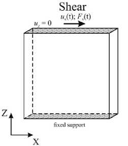
Fig. 2. The loads and boundary conditions in the single-element simulations
Table 1
Elastic properties of the fabric CFRP [50; 51]
|
E 1 , GPa |
Е 2 , GPa |
Е 3 , GPa |
G 12 , GPa |
G 13 , GPa |
G 23 , GPa |
µ 12 |
µ 13 |
µ 23 |
|
69.4 |
69.4 |
11.5 |
4.25 |
3.4 |
3.4 |
0.04 |
0.04 |
0.04 |
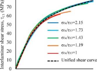
The parameters of expression (7) for describing the nonlinear response of the unified shear curve were determined based on the shear curves under combined loading (Fig. 3). The values beyond the interlaminar shear strains of 6% were excluded from the calibration because this level of shear strain corresponded to the moment where composite structure became discontinuous [50]. In this case, the stress-strain curves reflected the specimen deformation features rather than the actual material behaviour. The values of the parameters A , n for the material under consideration with an interlaminar strength of 49 MPa were 59.8 and 0.19, respectively. Parameter B was taken to be equal to 1.0.
The approximation results of the nonlinear response are shown in Fig. 3. Figure 3 shows that the nonlinear hardening in the combined loading tests [50] differed slightly depending on the type of loading and the corresponding stress combination σ 3 /τ 13 . Nevertheless, the correlation coefficient R 2 = 0.93 between the experimental response and the approximated unified shear curve demonstrated high accuracy in describing the nonlinear interlaminar shear curves in a limited strain range of up to 6 %.
0 1 2 3 4 5 6
Engineering shear strain. y13 (%)
Fig. 3. Approximation of experimental shear stress-strain curves
The nonlinear response of materials with higher interlaminar strength was extrapolated by varying the parameter B . Two levels of interlaminar strength of 80 and 100 MPa, which are typical for carbon fibre-reinforced plastics, were considered [52]. The value of the parameter B was 1.65 and 2.1, respectively. Then, using expressions (8)–(9), the stressstrain relations were calculated for each i-point used as input data for the multilinear material model in ANSYS (Tables 2–4).
The results of single-element simulation for materials with different interlaminar strengths are shown in Fig. 4. The mFEA approach adequately predicted the experimental nonlinear shear behaviour at strain levels up to 6 % for the material with the interlaminar strength of 49 MPa. It should be noted that the nonlinear stress-strain curves of materials with interlaminar strengths of 80 MPa and 100 MPa demonstrated the decrease in the level of inelastic strains at the same level of interlaminar shear stresses. The new approach to describing the nonlinear response was tested by assessing the static strength of dovetail specimens.
Table 2
Parameters of the shear curve fitting by multilinear kinematic hardening material model with interlaminar strength 49 MPa
|
Points |
τ, MPa |
p , % |
σ int , MPa |
pint , % |
|
1 |
19 |
0 |
65.8 |
0 |
|
2 |
32 |
0.07 |
110.8 |
0.04 |
|
3 |
41 |
0.21 |
142.0 |
0.12 |
|
4 |
47 |
0.36 |
162.8 |
0.21 |
|
5 |
52 |
0.53 |
180.1 |
0.31 |
|
6 |
56 |
0.73 |
194 |
0.42 |
|
7 |
59 |
0.94 |
204.4 |
0.54 |
|
8 |
63 |
1.33 |
218.2 |
0.76 |
|
9 |
67 |
1.74 |
232.1 |
1.0 |
|
10 |
69 |
2.07 |
239 |
1.2 |
|
11 |
72 |
2.51 |
249.4 |
1.45 |
|
12 |
75 |
3.03 |
259.8 |
1.75 |
Table 3
Parameters of the shear curve fitting by multilinear kinematic hardening material model with interlaminar strength 80 MPa
|
Points |
τ, MPa |
p , % |
σ int , MPa |
pint , % |
|
1 |
21 |
0 |
72.7 |
0 |
|
2 |
35 |
0.01 |
121.2 |
0.01 |
|
3 |
49 |
0.03 |
169.7 |
0.02 |
|
4 |
56 |
0.05 |
194 |
0.03 |
|
5 |
63 |
0.09 |
218.2 |
0.05 |
|
6 |
70 |
0.16 |
242.5 |
0.09 |
|
7 |
77 |
0.27 |
266.7 |
0.16 |
|
8 |
84 |
0.43 |
290.9 |
0.25 |
|
9 |
91 |
0.65 |
315.2 |
0.37 |
|
10 |
98 |
0.96 |
339.5 |
0.55 |
|
11 |
105 |
1.37 |
363.7 |
0.79 |
|
12 |
112 |
1.92 |
387.9 |
1.1 |
|
13 |
119 |
2.63 |
412.2 |
1.52 |
Table 4
Parameters of the shear curve fitting by the multilinear kinematic hardening material model with interlaminar strength 100 MPa
|
Points |
τ, MPa |
p , % |
σ int , MPa |
pint , % |
|
1 |
21 |
0 |
72.7 |
0 |
|
3 |
56 |
0.02 |
193.9 |
0.01 |
|
4 |
70 |
0.05 |
242.5 |
0.03 |
|
5 |
84 |
0.13 |
291 |
0.07 |
|
6 |
91 |
0.2 |
315.2 |
0.11 |
|
7 |
98 |
0.3 |
339.5 |
0.17 |
|
8 |
105 |
0.43 |
363.7 |
0.25 |
|
9 |
112 |
0.6 |
387.9 |
0.35 |
|
10 |
119 |
0.82 |
412.2 |
0.47 |
|
11 |
126 |
1.11 |
436.5 |
0.64 |
|
12 |
133 |
1.47 |
460.7 |
0.85 |
|
13 |
140 |
1.92 |
484.9 |
1.11 |
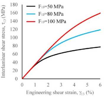
Fig. 4. Computational shear stress-strain curves
-
2.2. Description of the dovetail joint model
The new simplified approach to assess the stress-strain state and determine failure regions of the fan blade dovetail joint being typical thick-walled tapered composite element is presented in this section. The mesostructure features of the composite, such as ply drops and resin pockets, are not explicitly considered. The previously developed numerical approach to analyse the static strength of the dovetail joint [23] was extended to assess the influence of the interlaminar nonlinear response on the delamination load. The schematic of the dovetail joint was carried out based on the papers [4; 29]. The parameters which influence on the type of stress state and the delamination load were taken into account. The assessment of the stress-strain state and the delamination load of the numerical model of the dovetail specimen was carried out in ANSYS Workbench.
The geometry and boundary conditions of the dovetail joint were specified based on [4]. The main dimensions of the dovetail specimen are shown in Fig. 5.
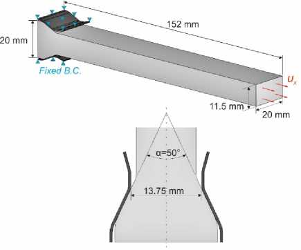
Fig. 5. Geometry, loads and boundary conditions of the dovetail joint
The numerical model of the dovetail joint using the mFEA approach was developed in several stages. First, the layer-by-layer stacking of structural sub-elements corresponding to the fibre was performed in ACP PrePost. Then, the structural sub-elements corresponding to the polymer matrix were generated at common nodes using the EGEN apdl command. The number of equivalent layers of the finite element model was 28. Each equivalent layer described the integral properties of the selected reinforcement scheme. The SOLID185 finite element was used. Based on the recommendations of [29], the FE size was set to 0.2×0.2 mm in the taper part of the dovetail specimen. The finite elements size was 0.2×0.4 mm in the thick part of the dovetail specimen. To reduce the total number of finite elements in the thin part of the dovetail specimen, 120 elements with bias factor=10 were specified. From the symmetry conditions, 1/4 of the dovetail joint was considered in the calculations. The total number of finite elements was 686851. The finite element mesh and orientation of the material properties in the layers are shown in Fig. 6.
The quasi-isotropic reinforcement scheme [0/45] S was used based on the recommendations [7]. In the FARGR-2 program [53], the elastic characteristics of the quasi-isotropic composite were determined to take into account the integral properties of the fabric composite in the finite element model (Table 5). The elastic parameters of the structural sub-elements for the corresponding laying were E 1 (1) = E 2 (1) =84.4 GPa, E 3 (1) =9.2 GPa, G 1 ( 2 1) =30.9 GPa and E (0)=13.8 GPa, μ(0)=0.015. The parameters of the sub-elements with elasticplastic properties were specified in accordance with Table 3.
Table 5
Elastic properties of quasi-isotropic composite [0/45] S
|
E 1 , GPa |
Е 2 , GPa |
Е 3 , GPa |
G 12 , GPa |
G 13 , GPa |
G 23 , GPa |
µ 12 |
µ 13 |
µ 23 |
|
49.3 |
49.3 |
11.5 |
18.9 |
3.4 |
3.4 |
0.04 |
0.04 |
0.04 |
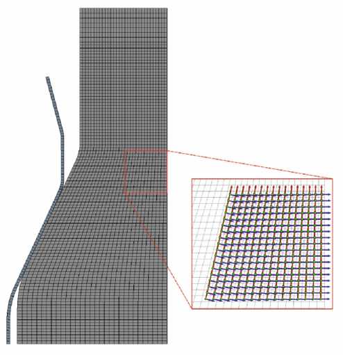
Fig. 6. Finite element mesh and orientation of element properties in layers
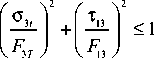
The kinematic loading was applied to the dovetail specimen. The displacement value was increased up to the ultimate load corresponding to one of the failure criteria. In the region of compressive transverse stresses, the failure from compression and from delamination was determined by the NU-Daniel criterion (10)–(11). In the region of transverse tensile stresses, the failure from delamination was determined by the Hashin criterion (12). The failure parameters used in the failure criteria are presented in Table 6. The interlaminar strength value of 80 MPa, typical for the VKU-39 material, was adopted as the base value [52]. This material was used in the development of the outlet guide vane [19; 21].
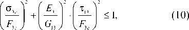
^3- 1 + 2 G 13 ° 3 c < 1, (11)
F a J E 3 • F a
where o 3c is through-thickness compression stresses, o 3t is through-thickness tension stresses, τ 13 is interlaminar shear stresses, F 3с is ultimate through-thickness compression strength, F 3t is ultimate through-thickness tensile strength, F 13 is ultimate inter-laminar shear strength, E 3 и G 13 are through-thickness modulus and interlaminar shear modulus, respectively.
Table 6
Strength properties of orthotropic fabric carbon fibre reinforced plastic [51; 52]
|
F 3 с , MPa |
F 31 , MPa |
F 3 t , MPa |
|
813 |
80 |
59.8 |
The failure stresses and safety factors were determined through the user defined result module. The safety factor was estimated as the ratio of stresses corresponding to the applied load to the maximum stresses determined using the corresponding NU-Daniel and Hashin failure criteria:
$ 3 c . NU F 3 c
= F 3 1
o

T .
G • o, 13 3 c
V E 3 • F 3
= F

-
3. Hashin , 13. Hashin
13.
Hashin
O 3 1 ( FEA )
T
T 13( FEA )
n _ min (n , n , ,„, n , nu , ), (17)
The contact type Frictional with Augmented Lagrange formulation was used between the disc and the dovetail specimen. The friction coefficient was set to 0.1 [4]. The disk was modelled as a rigid part with standard steel properties E =200 GPa, µ=0.3. The disk failure was not considered in this study.
-
2.3. Calculations results
The mFEA approach was used to determine the failure regions and delamination loads of the dovetail specimen. The strength assessment was carried out based on the analysis of stress fields in the layer coordinate system. The delamination load with the nonlinear mFEA approach was 43.3 kN. In the linear-elastic formulation the delamination load was 38.1 kN. The difference in delamination load was 13.6 %. This indicates a conservative estimate when using the linear elastic approach.
The distribution of safety factors, fields of interlaminar shear and transverse stresses are shown in Fig. 7–9. The areas of delamination of the dovetail specimen were determined based on the distribution of safety factors (Fig. 7). The safety factor in the taper part (zone 1) and thick part (zone 2) of the dovetail specimen was 1.01 and 1.02, respectively. Similar areas of delamination were obtained in [4] when assessing the delamination load of the dovetail specimen made of unidirectional carbon fibre.
The maximum interlaminar shear stresses were localized in the taper area of the dovetail specimen and achieved 113 MPa (Fig. 8). In the delamination regions the interlaminar shear stresses achieved 101 MPa and 102 MPa. The maximum transverse compressive stresses in this case were localized in the zone of contact between the dovetail specimen with the disk and achieved -517 MPa (Fig. 9), while the maximum transverse tensile stresses were localized in the taper region and achieved 37.3 MPa. The transverse stresses in the failure regions were -71.5 MPa and -75 MPa.
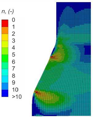
Fig. 7. The distributions of safety factors in the dovetail specimen
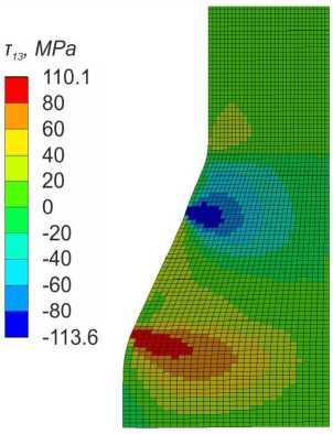
Fig. 8. The distribution of interlaminar shear stresses in the dovetail specimen
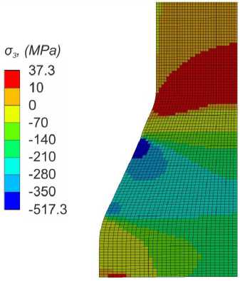
Fig. 9. The distribution of transversal normal stresses in the dovetail specimen
The obtained safety factor estimates only the beginning of the delamination of one or more layers. After the first delamination, the load is redistributed to the undamaged layers with different reinforcement angles, including the area of combined tension/shear, where the delamination growth is not restrained by transverse compression.
Additional computational studies were conducted to assess the sensitivity of the numerical results to the parameters of the numerical model. First of all, the interlaminar strength values were varied in the range from 50 MPa to 100 MPa. In this way, the influence of various physical factors on the delamination load was assessed. Increased operating temperatures can lead to the decrease in interlaminar strength [54]. At the same time, the use of specially modified polymer matrices in composites allows to increase the interlaminar strength significantly [2]. In addition, the assessment of the interlaminar strength from the transverse compression force when changing the wedge angle of the dovetail joint α from 40° to 60° was performed.
Figure 10 shows the values of the delamination load for different values of interlaminar strength. It was found that the interlaminar strength of 100 MPa, the delamination load is 50.3 kN, while at the interlaminar strength of 50 MPa, the delamination load is significantly reduced to 27.7 kN. This indicates that the delamination load of such elements is largely determined by the interlaminar strength. Figure 11
shows the values of the delamination load for different taper angles of the dovetail specimen. It was found that at the taper angle of 60°, the delamination load was 47.5 kN, while at the taper angle of 40°, the delamination load significantly reduced to 32.6 kN. Thus, the through-thickness compression effect prevents delamination with the increase in the taper angle.
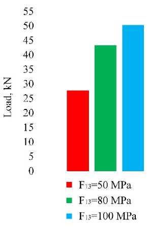
Fig. 10. The delamination load values for different interlaminar strengths
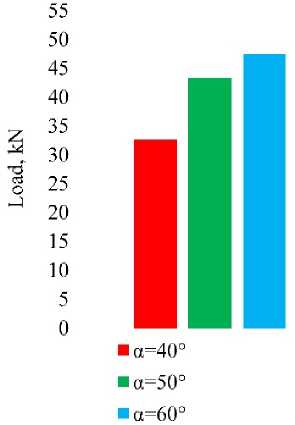
Fig. 11. The delamination load values for different taper angles
Therefore, the interlaminar strength and taper angle should be increased to provide higher delamination load for the dovetail joint. However, there is another design limitation associated with the failure from transverse compression in the contact zone of the dovetail specimen with the disk or from delamination in the zone of tensile transverse stresses. The safety factors for stress components for all loading cases are presented in Table 7. It was found that the safety factor according to the Hashin criterion was close to 1 for the taper angle of 60 degrees. While the safety factor for transverse stresses according to the NU-Daniel criterion was close to 1 at the interlaminar strength of 100 MPa. In this case, the increase in the taper angle or interlaminar strength is limited, since this will lead to a change in the failure mechanism. Using these failure mechanism constraints could be useful during determination of a rational dovetail joint of the full-scale fan blades.
Table 7
Safety factors and delamination loads for all cases of numerical calculations
|
τ 13 , MPa |
α, ° |
F , kN |
n 13 .Hashin |
n 3 .Hashin |
n 13 .Daniel |
n 3 .Daniel |
|
80 |
40 |
32.6 |
2.38 |
2.1 |
1 |
1.68 |
|
50 |
43.3 |
1.54 |
1.39 |
1 |
1.5 |
|
|
60 |
47.5 |
1.1 |
1.05 |
1 |
1.8 |
|
|
50 |
50 |
27.7 |
1.44 |
2 |
1 |
2.6 |
|
100 |
50.3 |
1.37 |
1.17 |
1 |
1.13 |
Conclusion
The paper presents the theoretical foundations and the example of practical use of the new approach to determine the failure regions of tapered thick-walled composite elements at the design stage. The approach is based on the modified mFEA approach which describes nonlinear deformation under transverse-shear loading.
The parameters of the sub-elements of the constitutive mFEA model were identified using experimental data from standard tests and under combined transverse-shear loading tests. The nonlinear response of the material in the model was described based on the unified interlaminar shear curve. Calibration on the single finite element showed that the modified mFEA approach demonstrated high accuracy in predicting the nonlinear mechanical response of fabric FRP under transverse-shear loading at a shear strain of up to 6 %.
