A Non-format Compliant Scalable RSA-based JPEG Encryption Algorithm

Author: Aniruddha G. Phatak
Journal: International Journal of Image, Graphics and Signal Processing(IJIGSP) @ijigsp
Article in issue: 6 vol.8, 2016.
Free access
A non-format compliant JPEG encryption algorithm is proposed which is based on a modification of the RSA encryption system. Firstly, an alternate form of entropy coding is described, which is more suited to the proposed algorithm, instead of the zigzag coding scheme used in JPEG. The algorithm for the encryption and decryption process is then elaborated. A variant of the algorithm, also based on the RSA algorithm is also described, which is faster than the original algorithm, but expands the bit stream slightly. Both the algorithms are shown to be scalable and resistant to 'sketch' attacks. Finally, the encrypted file sizes for both the algorithms are compared with the unencrypted JPEG compressed image file size. The encrypted image is found to be moderately expanded, but which is justified by the high security and most importantly, the scalability of the algorithm.
Image encryption, non-format compliant algorithm, RSA, JPEG, scalability, sketch attacks
Short address: https://sciup.org/15013989
IDR: 15013989
Text of the scientific article A Non-format Compliant Scalable RSA-based JPEG Encryption Algorithm
Published Online June 2016 in MECS DOI: 10.5815/ijigsp.2016.06.08
-
I. Background And Related Work
Due to the increased sophistication of tools available at the hands of intruders, sharing of sensitive images over an insecure channel has become extremely risky. This is even more of a concern for JPEG images, which form the significant bulk of the images transferred over any communications network, such as the Internet, due to their extremely high compression ratio at the cost of almost imperceptible loss in image quality. The special nature of the JPEG encoding process makes JPEG-related algorithms a class apart from those applied to other image formats. There are two broad categories of JPEG encryption--format-compliant [4][5][9][10] and nonformat-compliant. In the former case, the encryption algorithm is bound by the restriction that the encrypted output must conform to the JPEG algorithm and format. In the latter case, there is no such restriction and hence, these class of algorithms can afford to be much more flexible and inventive. Format-compliant algorithms usually are based on shuffling of DC coefficients [Niu et al., 5], randomly shuffling the signs of the AC coefficients, a combination of several scrambling and shuffling operations using the XOR operation [12], a combination of several operations at the bit stream level [4], permutation of the zigzag scheme used in JPEG encryption [11] or the use of fuzzy PN sequences [9].
Another class of JPEG encryption involves chaos theory elements such as 2D chaos maps, such as the Arnold’s cat map, Baker’s Map [6] or the Duffing’s Map, chaotic sequence [7] or spatiotemporal chaos [8]. Still another category is the use of space-filling curves [13], combined with a chaotic stream cipher [14]. Most of the format-compliant algorithms were shown by Li and Yuan [1] to be leaky to ‘sketch’ attacks, while most of the algorithms resistant to such attacks end up significantly expanding the bit stream[1][2].
In this paper, a non-format compliant algorithm is proposed which is based on the RSA encryption algorithm. Instead of the 8x8 blocks used in the JPEG algorithm, 16x16 blocks are used. The alternate entropy coding scheme used is centered on defining a particular shape inside the quantized DCT matrix, such that all the non-zero coefficients are included within this shape. The parameters defining this shape are then transmitted separately and securely. This alternate scheme is shown to be resistant to ‘sketch’ attacks, in which a silhouette of the original image is obtained simply by thresholding the number of non-zero AC coefficients in the JPEG encrypted files. An alternate variant of the algorithm is also described, which is faster than the original algorithm, but expands the bit stream slightly. The security provided by the two algorithms proposed is shown to be scalable, such that security is increased largely at the cost of execution time in the first variant, and largely at the cost of bit stream (or image file) size expansion in the second variant.
The encryption algorithm used in this paper is not strictly RSA (since no public-key component is present), but is based on it. However, the encryption algorithm will still be referred to as RSA algorithm in the rest of the paper for the sake of brevity.
This paper consists of two broad sections—in the first section, the entropy coding used in the algorithm is This paper consists of two broad sections—in the first section, the entropy coding used in the algorithm is described, followed by the second section, in which the actual compression algorithm is introduced.
-
II. Entropy Coding Algorithm Description
The algorithm is described for a 8x8 block. The same can be extended to 16x16 blocks easily.
For each 8x8 quantized block of DCT coefficients, a particular shape is defined, such that all non-zero coefficients are contained within the shape. This shape is obtained by the following process:
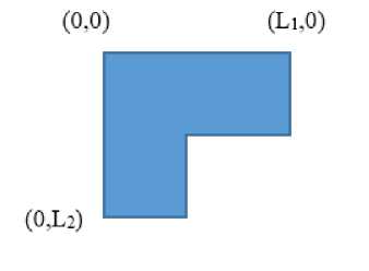
Let the 8x8 matrix be defined in a Cartesian coordinate system, with the origin at the top-left corner of the matrix, the x-axis extending along the top edge and the y-axis extending along the left edge of the matrix.
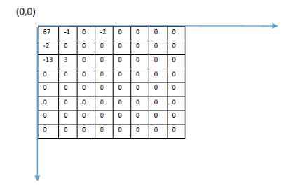
Fig.1. (A) 8 X 8 Matrix
Initially a square is defined such that its length is equal to the coefficient farthest from the origin, either in the X-direction or the Y-direction.
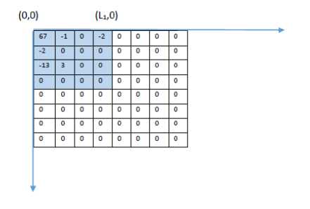
Fig.1. (B) square area s 1
Let this square be called S 1 and the length be L 1 .
Now starting from the bottom-right corner of this square (i.e. at position (L 1 ,L 1 ) ), each m x m block of coefficients is scanned, extending into the square of length L1.
If all the coefficients in a m x m block are zero, then the value of m is incremented and the next m x m block is scanned. The process is repeated until a non-zero element is found in the m × m block. Then the value of highest value of m, such that all coefficients in the m x m block are zero, is noted. Let this value be equal to L 2 and the square thus defined by length L 2 be called S 2 .
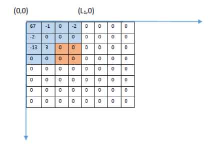
Fig.1. (C) Second Square S 2
The square S2 is snipped from the bottom-right section of square S1.
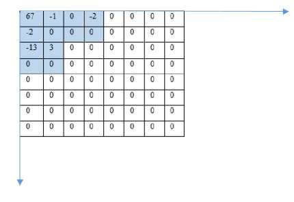
Fig.1. (D) Square S 2 Snipped from the Square S 1 (See Fig.1 (C)
Hence the shape now defined has the following shape:
-
Fig.1. (E) Final Shape and The Coordinates of the Edge Points
The coefficients contained in the shape are now numbered serially from 1 to (L 12 – L 22 ) starting from the origin (top-left corner), left to right, top to bottom, in the following manner.
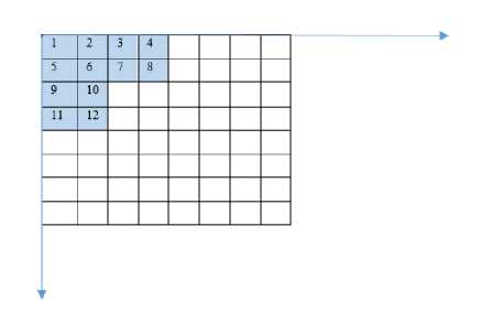
Fig.1. (F) Serial Numbering of the Squares in the Shape
-
III. Encoding of Coefficients
After the coefficients are ordered as a single string of integers, the entropy coding of these integers is necessary. The process used in this algorithm is a slight variant of the coding process used in the JPEG system. Keeping in mind the large number of zeros and frequent repetition in the integer stream to be encoded, a zero indicator and a repetition indicator bit are added prefixed to each encoded integer. Also, in the proposed algorithm, the number of bits needed to encode each pixel is encoded separately as a Huffman encoded stream, while in JPEG, this information is encoded along with the value of the pixel. A more formal discussion of the encoding algorithm is given below –
Each of the coefficients is encoded serially in the following format:
1 2 3 4
-
Fig.2. Representation of Each Coefficient
-
1 – Zero bit indicator
-
2 – Repetition Indicator
-
3 – Sign of the coefficient
-
4 - Binary representation of the absolute value of coefficient
-
• Zero-bit indicator : Used to indicate whether the coefficient is zero or non-zero. If the coefficient is zero, then a 0 is written and rest of the fields are ignored, otherwise a 1 is written.
-
• Repetition indicator: In the coefficient is a repetition of the previous coefficient, then a 1 is written to this field, and the rest of the fields are ignored.
-
• Sign of the coefficient: 1 if the coefficient is positive, otherwise 0.
The number of bits needed to represent the value of each non-zero, non-repeated coefficient are concatenated together (as per the serial number of coefficients) and are Huffman encoded. The Huffman dictionary used is shown below. The user may define their own Huffman dictionary to suit their particular application.
Table.1. Huffman Dictionary For The Luma Plane
|
Value |
Huffman Code |
|
1 |
00 |
|
2 |
11 |
|
3 |
010 |
|
4 |
0110 |
|
5 |
011100 |
|
6 |
011111 |
|
7 |
011110 |
|
8 |
0111010 |
|
9 |
01111011 |
|
Delimiter |
01 |
Table.2. Huffman Dictionary For Chroma Planes
|
Value |
Huffman Code |
|
1 |
1 |
|
2 |
000 |
|
3 |
0010 |
|
4 |
00110 |
|
5 |
001110 |
|
6 |
0011111 |
|
7 |
0011110 |
|
Delimiter |
01 |
(The delimiter is needed to signal the end of the Huffman encoded bit stream.)
Finally, the entire image is encoded in the following manner:
I 1 ZZ 2 ZZ
-
Fig.3 Encoding of Entire Image
-
1 – Huffman encoded bit stream of the number of bits needed to represent each coefficient
-
2 – Coefficients encoded as per Table 1 above
This data constitutes the ‘DCT block data’ as will be referred to in the following sections. Note that it is not possible to decode the image unless the values of L1 and L2 for each of the 16x16 blocks is known. This fact is exploited in the next section, which deals with encryption.
-
IV. Encryption Algorithm Description
In Sections II and III, the encoding process of the DCT coefficients was described in detail. In the following sections, the encryption algorithm will be described and the related results will be presented.
-
A. Encoding Process
(The following description assumes a 512x512 image, thus having 1024 16x16 blocks.)
-
1. The DCT blocks are scrambled using a w-bit long key (called as a scrambling key) using any of the scrambling algorithm described in literature.
-
2. The values of L 1 and L 2 are arranged as an integer of 2048 decimal digits, two digits corresponding to one 16x16 block. Let them be called J and K respectively.
-
3. J and K are divided into 2 parts called as J1 & J2 and K1 and K2 respectively. Let J1 have d1 decimal digits and b1 binary digits and k1 have d2 decimal and b2 binary digits. (for the rest of the paper, d1=d2=d).
-
4. The value of J1 and K1 are adjusted so that they are made equal to the nearest prime number. This is done by adding 1 to their value if they are not already odd, and then applying probabilistic primality tests, such as the Miller-Rabin strong pseudo prime test. Repeat this procedure (i.e. go on incrementing 2 to the odd numbers) till the numbers are found to be prime with probability above a sufficient threshold. This will probably distort the last 1-2 digits of J1 and K1, which may be appropriately taken care of in the header of the image file, or may be left as they are if minor errors in the output image are tolerable.
-
5. J1 and K1 thus formed are the two large prime numbers required in the RSA cryptosystem.
-
6. The key is then formed by multiplying J1 and K1 (called as N1). N1 has a maximum of and approximately equal to b1+b2 number of bits and hence the RSA system is equivalent to a (b1+b2)-RSA cryptosystem.
-
7. The w-bit key mentioned in step 1 is randomly padded as per the RSA specifications. (Ensuring that w+p < (b1+b2), where p is the number of bits padded.)
-
8. The value of the Euler’s totient function Φ, small exponent e and the modular multiplicative inverse of e, called as d, are then calculated. The same values of Φ, e and d are made available to the receiver by the following process:
-
9. The receiver can calculate the value of Φ, since the value of J1 and K1 is known. Then among the infinite set of possible values for e, the nth value is chosen, with the value of n being communicated to the receiver, possibly in the header of the image file. Also, since the value of d is given by the following equation:
-
10. The key of length w+p bits is then encrypted using the RSA encryption formula:
-
11. Each digit of J2 and K2 is transmitted as a pair (J2,K2) of 8 bits (4 bits for each of the two elements in the pair.)
-
12. The actual image data is transmitted in the following format:
e × d -1 = n × Φ (1)
where n is any integer.
The value of d may be calculated by the receiver by knowing the value of n, which, similar to e, is a fairly small value and may be communicated to the receiver in the header of the file.
C = (w+p)e mod (N1) (2)
bl- b2 bits bl -b2 bits
-
Fig.4. Actual Image Data
-
1 – N1
-
2 - (J2, K2)
-
3 – RSA encrypted scrambling key
-
4 – Actual DCT block data as per the format (encoded prior to scrambling)
-
13. The secret image key for the entire image, which is transmitted securely and separately, consists of the following values:
|
1 |
2 |
Fig.5. Secret Image Key
-
1– Value of (b1+b2), nominally 24 bits
-
2 – Binary representation of J1
-
B. Decoding Process
-
1. The value of J1 is extracted from the image data since the number of bits it occupies is known from the secret key (b1+b2).
-
2. Since the value of the public key N1 is known from the actual image data, the value of K1 is easily calculated from N1 and J1 (which is known from the secret key) and thus, the two large prime numbers are made available at the receiver.
-
3. The values of e and d are calculated as described in step 8 in the encoding section.
-
4. The scrambling key of w+p bits used to scramble the blocks is then calculated by applying the RSA decrypting formula:
-
5. After the original key of w bits is recovered (after discarding the padding p), the blocks are rearranged in the original order.
-
6. Since J1 and K1 (i.e. the values of L 1 and L 2 for all 1024 blocks) are known, the DCT block data is decoded and the image is recovered.
w + p = Cd mod (N1) (3)
-
V. Example
The algorithm described above is illustrated using a typical example.
-
A. Encoding Example
-
1. The blocks are scrambled using a 1024-bit long scrambling key using any of the scrambling algorithm described in literature.
-
2. The values of L1 and L2 are arranged as an integer of 1024 decimal digits, each digit corresponding to one 16x16 block. Let them be called J and K respectively.
-
3. J and K are divided into 2 parts, J1 & J2 and K1 and K2 respectively, with J1 and K1 having d=170 decimal digits and thus each having approximately 570 bits. (b1=b2=570)
-
4. J1 and K1 are rounded to the nearest prime numbers as discussed in (4) in the encoding section.
-
5. The RSA key N1 is obtained by multiplying J1 and K1. Hence N1 has approximately (and a maximum of) b1+b2=1400 bits. Hence the system is equivalent to RSA-1400 or RSA with a key length of 1400 bits.
-
6. The 1024 scrambling key is padded as per the OAEP padding scheme.
-
7. The values of e and d are calculated as per (8) in the encoding section and the appropriate values are mentioned in the header section (so that the receiver can obtain the same value of e and d.)
-
8. The scrambling key is encrypted according to the RSA encrypting formula as in (10) in the encoding section. The encrypted value is 1400 bits in length.
-
9. Each pair of digits of J2 and K2 (J2 and K2 have (2048-170)/2= 939 digits pairs) is transmitted as a pair (J2,K2) of 8 bits (4 bits for each of the two pairs in (J2,K2)) Hence total number of bits required is:
-
939 x 2 x 4 = 7512 bits
1 2 3 4
1400 bits 7512 bits
-
Fig.6. Transmitted Image Data
-
1 – N1
-
2 - (J2, K2)
-
3 – RSA encrypted scrambling key
-
4 – Actual DCT block data as per the format (encoded prior to scrambling)
-
4 . The values of e and d are calculated as described in (8) in the encoding section.
-
5 . The scrambling key of 1024 bits used to scramble the blocks is then calculated by applying the RSA decrypting formula as in (4) of the decoding section.
-
6 . This key is then used to rearrange the 1024 DCT blocks (i.e. reverse the scrambling.)
-
7 . By using the values of L1 and L2 and the actual DCT block data (in the transmitted image data), the DCT blocks are reconstituted and the image is thus successfully obtained.
appended to K1. In this way, J and K are formed and thus values of L1 and L2 are recovered for each block.
-
VI. Security Analysis
In this section, the resistance of the algorithm to brute force attacks is investigated. It is shown that the algorithm is extremely secure and that it is impractical for any attacker to brute force the algorithm.
-
A. Resistance to Brute Force Attack
Any attacker employing brute force has two choices:
-
1. To attack the RSA algorithm itself: Note that this is almost impossible, since the attacker employing a brute force attack is unaware of the actual length of the RSA key itself. Hence the attacker will have to take a guess at a particular key length, and then go on incrementing the key till the right key length is found. Hence, the algorithm is at best several times more secure than and at least as secure as, RSA algorithm of key length (b1+b2), if this line of attack is used.
-
2. The second line of attack is to step through the key space of length w and for each key, iterating through the possible combinations of L1 and L2. Hence the maximum number of such trials required would be:
(w)! x (136)1024 (4)
Since there are 136 possible combinations of L 1 and L 2 for a 16x16 matrix.
1 2
24 bits 570 bits
Fig.7. Secret Image Key
1– Value of (b1+b2) = 1400
2– Binary representation of J1
-
B. Decoding Example
-
1. The first 1400 bits are extracted from the transmitted image data. This is the value of N1.
-
2. The remaining bits are extracted from the secret image key. This is the value of J1.
-
3. K1 is calculated from N1 and J1 as K1=N1/J1.
-
4. The values of J2 and K2 are extracted from the transmitted image data. J2 is appended to J1 and K2 is
-
-
VII. Algorithm Variant 2
In this section, a slight variant of the above described encryption algorithm will be presented. In this section it will be shown that this variant is faster but expands the resultant file (or the bit stream) slightly. Hence, selecting one of the two algorithm variants involves a trade-off between execution speed and the final size of the encrypted image.
In this variation of the algorithm described above, two completely random prime numbers, P1 and P2, of bitlength b1 and b2, are chosen and are multiplied together to obtain N, the RSA key, of maximum bit length (b1+b2). J and K are not split and are transmitted in full.
|
1 |
2 |
3 |
4 |
Fig.8. Transmitted Image Data For Variant 2
-
1 – N
-
2 - (J, K)
-
3 – RSA encrypted scrambling key
-
4 – Actual DCT block data as per the format (encoded prior to scrambling)
The secret image key consists of the bit length of N and one of the prime numbers, P1.
-
1 2
-
Fig.9. Secret Image Key For Variant 2
-
1 – Value of (b1+b2) i.e. bit length of N
-
2 – Binary representation of P1
Note that this variant is faster than the first variant since the primality testing of (4) in the encoding of the first variant is now avoided. Also, there is no need to distort the last few digits of J1 and K1 in order to convert them to prime numbers.
However, this variant expands the bit stream size slightly, since N and the pair (J, K) are independent and need to be transmitted individually in full.
-
VIII. Algorithm Scalability
In addition to the high security, the proposed algorithm is also scalable. The algorithm allows key lengths of varying sizes; hence, the user may increase the length of the security key to increase the security of the algorithm. This increased security comes at the cost of increased time of execution and expanded file size.
-
A. Variant 1:
The algorithm could be made more secure (or possibly, less so) by changing the length of the scrambling key w used to scramble the DCT blocks; more the key length, more the key space to step through in the formula (1) above and hence more secure the algorithm. Note that the length of the RSA key N1 (by increasing the length of J1 and K1) in the actual image data and the value of J1 in the secret image key would also need to be increased proportionally since w + p < (b1+b2)
where b1 is the number of bits in J1, b2 is the number of bits in K1 and hence (b1+b2) is the maximum and approximate number of bits in N1. However, the values of J2 and K2 are then proportionally decreased, with the effect that the file size is not significantly affected and remains almost the same, even if the algorithm is scaled. (However, the image key size is increased.)
The execution time of the algorithm will be increased with increased security, since the primality tests explained in (4) will now have to be carried out for larger values of J1 and K1.
-
B. Variant 2:
Increasing the length of the scrambling key w will necessitate the increase in the length of the RSA key N (and hence increase in the values of P1 and P2) because of formula (2). Hence, the image file size is increased proportionally, since, unlike in variant 1, the number of pairs (J, K) do not decrease as N is increased.
However, the execution time of the variant 2 remains almost the same, since P1 and P2 are chosen at random, and there is no need to carry out primality tests, which are time-consuming.
Therefore it can be concluded that, as the security of the algorithm is increased, variant 1 increases the execution time slightly but maintains almost the same bit stream(or file) size, whereas variant 2 increases the bit stream(or file) size slightly, while maintaining almost the same execution time. Hence, the choice between variant 1 and variant 2 may be considered to be essentially a time vs. space tradeoff
-
IX. Resistance To Sketch Attacks
It was shown by [1] that most of the (format-compliant) JPEG encryption algorithms are leaky and susceptible to the so-called ‘sketch’ attacks, in which the number of non-zero AC coefficients are thresholded—if the number of AC coefficients in a particular block is above a particular threshold, then a 1 written to a bitmap at the position of the block, otherwise a 0 is written. In this way, it is possible to obtain a scaled down binary ‘sketch’ (outline) or a silhouette of the image, which may be satisfactory for some intruders. Most of the JPEG encryption algorithms rely on scrambling the sign of the AC coefficients by XORing them with a random bit stream, or scrambling the elements of the blocks themselves. For the sketch attack to be successful, the intruder must be aware of the number of elements in each block. However, in this algorithm, since this information is part of the encrypted data, it is not possible for the intruder to apply this method and cause the encrypted image to ‘leak’ data.
-
X. Results
-
1. In this section, the effect of the algorithm on the final length of the bit stream is reported. The parameters are as mentioned in the encoding example section. The quality factor is set at 50.
-
2. The quantization matrix for the 16x16 blocks used in the algorithm is obtained by expanding each element of the original 8x8 quantization matrix, as recommended for quality factor of 50, into a 2x2 matrix.
-
3. The size reported is for the entire image, including the two chroma components (subsampled at 4:2:0), with each chroma component having the length of the
-
4. The size of the encrypted image is excluding the secret image key, which must be transmitted separately.
scrambling key and N1 as 300 bits. (i.e. security at least equal to RSA-300.)
Test Image Set:
(d)

(e) (f)

(g)
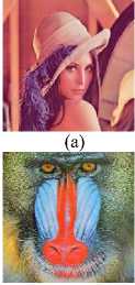
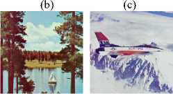
Fig.10. Test Image Set (A) Lena (B) Peppers (C) Fruits (D) Baboon (E) Sailboat (F) Aeroplane (G) Macaw
-
A. Algorithm Variant 1
Table.3 Results For Algorithm Variant 1
|
Sr No |
Image |
Unencrypted JPEG file size |
Encrypted file size (excluding the secret key) |
Percent increase in file size |
|
1 |
Lena (512 x 512) |
24.450 |
24.331 |
-0.4867 |
|
2 |
Peppers (512 x 512) |
25.540 |
28.283 |
10.740 |
|
3 |
Fruits (512 x 512) |
24.410 |
26.681 |
9.303 |
|
4 |
Baboon (512 x 512) |
49.485 |
49.577 |
0.1859 |
|
5 |
Sailboat (512 x 512) |
33.355 |
36.880 |
10.568 |
|
6 |
Aero plane (512 x 512) |
25.180 |
26.809 |
6.4694 |
|
7 |
Macaw (512 x 512) |
19.654 |
20.615 |
4.8895 |
-
B. Algorithm Variant 2
Table.4. Results For Algorithm Variant 2
Sr No
Image
Unencry pted JPEG file size
Encrypted file size (excluding the secret key)
Percent increase in file size
1
Lena (512 x 512)
24.450
24.461
0.0449
2
Pepper s (512 x 512)
25.540
28.413
11.2490
3
Fruits (512 x 512)
24.410
26.411
8.1974
4
Baboo n (512 x 512)
49.485
49.707
0.4486
5
Sailbo at (512 x 512)
33.355
37.010
10.9578
6
Aeropl ane (512 x 512)
25.180
26.939
6.9857
7
Maca w (512 x 512)
19.654
20.745
5.5510
As can be seen from the result table, both the algorithms expand the bit stream size (variant 2 more so). However, this slight expansion is justified by the scalability and the high security provided by the algorithm.
-
XI. Conclusion
A RSA-based non-format compliant JPEG encryption algorithm along with the alternate entropy coding scheme (as opposed to the zigzag scheme used in JPEG) used in the algorithm was described in the paper. A variant of the algorithm was also presented. The described algorithms gives high security and expand the bit stream only incrementally. Moreover, the algorithms are scalable, which is an additional advantage of the algorithm.
References A Non-format Compliant Scalable RSA-based JPEG Encryption Algorithm
- Weihai Li, Yuan Yuan, 'A leak and its remedy in JPEG image encryption', International Journal of Computer Mathematics, Volume 84, Issue 9, 2007.
- M. Takayama, K. Tanaka, K. Takagi, Y. Nakajima, 'A scalable video scrambling method in MPEG compressed domain', International Symposium on Communications, Control and Signal Processing, 2008.
- S. Yong, K. Yong, X. Qi, K. Tanaka, 'Beyond format compliant encryption for JPEG images', Signal Processing: Image Communication, Volume 31, February 2015, Pages 47–60.
- S. Auer, A. Bliem, D. Engel, A. Uhl, A. Unterweger, 'Bitstream-Based JPEG Encryption in Real-time', International Journal of Digital Crime and Forensics, 5(3), 1-14, July-September 2013.
- X. Niu, C. Zhou, J. Ding, B.Yang, 'JPEG Encryption with File Size Preservation', IIHMSP '08 International Conference on Intelligent Information Hiding and Multimedia Signal Processing, 2008, pp. 308 – 311.
- Shiyu Ji, Xiaojun Tong, Miao Zhang, 'Image encryption schemes for JPEG and GIF formats based on 3D baker with compound chaotic sequence generator', School of computer science and Technology, Harbin Institute of Technology, Weihai, 264209, China.
- D. Zhang, F. Zhang, 'Chaotic encryption and decryption of JPEG image', Optik - International Journal for Light and Electron Optics, Volume 125, Issue 2, January 2014, Pages 717–720.
- Y. Luo, M. Du, D. Liu, 'JPEG Image Encryption Algorithm Based on Spatiotemporal Chaos', 2012 Fifth International Workshop on Chaos-Fractals Theories and Applications (IWCFTA), 18-21 Oct. 2012 pp 191 – 195.
- B. K. ShreyamshaKumar, Chidamber R. Patil, 'JPEG image encryption using fuzzy PN sequences', Signal, Image and Video Processing, November 2010, Volume 4, Issue 4, pp 419-427.
- A. Unterweger, A. Uhl, 'Length-preserving bit-stream-based JPEG encryption', MM&Sec '12 Proceedings of the on Multimedia and security, pp 85-90.
- C. Kailasanathan, R. Safavi-Naini, P. Ogunbona, 'Compression performance of JPEG encryption scheme', 14th International Conference on Digital Signal Processing, 1-3 July 2002, Vol 2, pp. 1329-1332.
- Kazuki Minemuraa, Zahra Moayeda, KokSheik Wonga, Xiaojun Qib, Kiyoshi Tanakac, 'JPEG image scrambling without expansion in bitstream size', 2012 19th IEEE International Conference on Image Processing (ICIP), pp 261-264.
- V. Suresh and C.E. Veni Madhavan, 'Image Encryption with Space-filling Curves', Defence Science Journal, Vol. 62, No. 1, January 2012, pp. 46-50.
- Shiguo Lian, Jinsheng Sun, Zhiquan Wang, 'A novel image encryption scheme based-on JPEG encoding', Eighth International Conference on Information Visualisation, 2004. IV 2004. Proceedings, pp 217-220.
