A Novel Approach of Image Based Steganography Using Pseudorandom Sequence Generator Function and DCT Coefficients

Author: Anupam Mondal, Shiladitya Pujari
Journal: International Journal of Computer Network and Information Security(IJCNIS) @ijcnis
Article in issue: 3 vol.7, 2015.
Free access
This research paper present a novel approach of Image based steganography scheme where a pseudorandom sequence generator function is used to randomize the mapping sequence in a pseudorandom fashion. The embedding process of the secret message is done according to the pseudo-random sequence, and extraction is done using the same sequence at the other end. At the base level, 2D-DCT is used to hide the bits of secret message inside the stego image by replacing the LSBs of DCT coefficients. Since in previous paper the LSB substitution technique is already used, here in this paper the previous concept is extended and used DCT instead of LSB technique. A new text randomization algorithm (4-2 swap text randomization algorithm) is also used to modify the secret message before embedding.
Steganography, Security, Pseudorandom, DCT
Short address: https://sciup.org/15011395
IDR: 15011395
Text of the scientific article A Novel Approach of Image Based Steganography Using Pseudorandom Sequence Generator Function and DCT Coefficients
Steganography is the art as well as the science of hiding information into another covering media in such a way that nobody except the intended recipient knows about the secret message and retrieve it. Steganography (means “covered writing” in Greek) is an old art that has been used since the golden age of Greece where some practices were recorded like: writing a message on a wooden table then covering it with wax. Other techniques use invisible ink, microdots, converting channels and character arrangement. Steganography is a type of cryptography in which the secret message is hidden in a digital picture. Steganography differs from Cryptography in the sense that where cryptography focuses on keeping the contents of a message secret, whereas steganography focuses on keeping the very existence of the message secret[1-3].
Various image based steganography method namely LSB(least-significant-bit),PVD(pixel-value differencing),
GLM(gray level modification) and the method proposed by Ahmed et al. has been briefly mentioned in the following section.
-
A. Data Hiding by Least Significant Bit (LSB)
The most popular and common techniques is based on manipulating the least-significant-bit (LSB) [9], [10] and [11] planes by directly replacing the LSBs of the cover-image with the message bits. LSB methods typically achieve high capacity but unfortunately LSB insertion is vulnerable to slight image manipulation such as cropping and compression.
-
B. Data Hiding by Pixel Value Differencing Method
Another method proposed by Wu and Tsai, the pixelvalue differencing (PVD) method can successfully provide both high embedding capacity and outstanding imperceptibility for the stego image. Based on PVD method, various approaches have also been proposed. Among them Chang et al. proposes a new method using tri-way pixel-value differencing.
-
C. Data Hiding by GLM
In 2004, Potdar et al. [11] proposes GLM (Gray level modification) technique which is used to map data by modifying the gray level of the image pixels. Gray level modification Steganography is a technique to map data (not embed or hide it) by modifying the gray level values of the image pixels.
-
D. Data Hiding by the Method Proposed by AHMAD et al.
In this work a novel Steganography method for hiding information within the spatial domain of the gray scale image has been proposed. The proposed approach works by dividing the cover into blocks of equal size and then embeds the message in the edge of the block depending on the number of ones in left four bits of the pixel.
The paper has been arranged in some sections. Section I mentioned a brief introduction and a discussion on the related works in the relevant field. Section II defined about some steganographic methods. The next section (III) described the proposed procedure. Section IV described the overall procedure via an example. Next section (V) of the paper is about analyzing the experimental result. The last section (VI) concluded on the research paper.
-
II. Steganographic Methods
There are mainly three ways to hide a digital message in a digital cover [5][7][8][9].
-
A. Injection
Data injection embeds the secret message directly in the host medium. The problem with this kind of embedding is that it usually makes the host file larger, and therefore the alteration is easier to detect.
-
B. Substitution
Normal data is replaced or substituted with the secret data. This usually results in very little size change for the host file. However, depending on the type of host file and the amount of hidden data, the substitution method can degrade the quality of the original host file.
-
C. Generation of New Files
A cover is generated for the sole purpose of concealing a secret message. A sender creates a picture of something innocent that can be passed to receiver; the innocent picture is the cover that provides the mechanism for conveying the message.
Digital images can be dealt in two different domains. One is the spatial domain, where the image is considered as the two dimensional array of pixels oriented in a table format. On the other hand, in the frequency domain, images are considered as the digital signal transmitted through the physical media. In this research paper 2D Discrete Cosine Transform (2D-DCT) method [6] is used instead of Least Significant Bit (LSB) substitution technique as the fundamental hiding technique [4].
-
III. The Proposed Scheme Of Steganography
In this paper a new image based steganography scheme is presented in which both the secret message as well as the cover image is divided into a number of small but equal sized segments [4]. After that segmentation, separate segments of the secret message are embedded by using LSB method at the DCT coefficients of those image segments, but a particular segment of the cover image for a particular segment of text is selected in a pseudo-random fashion. This method makes the embedding or insertion process difficult, but imposes more security [4]. Analysis may help to detect that steganography has been implied on the cover image, but attackers cannot be able to extract the secret message from the cover image without knowing the parameters used in this process.
-
A. Embedding Method
This new steganography method is block mapping method. The entire Steganography process has two parts. One part is to insert or hide the secret text message inside a cover image, preferable colored image. This process is done at the sending end. Another part is used at the receiving end to extract the original secret text message from the stego-image.
S tep 1
The secret message is taken as the primary input. This is the secret message to be hidden inside the cover image. Total number of characters (Ch) of the secret message is counted.
S tep 2
A unique integer number named Threshold (T) is calculated through a unique message digest mechanism. It takes a one-time Password , a fixed Key (For advanced security purpose) and the secret message as input. Depending on the total number of characters and the strength of password, Threshold is calculated.
S tep 3
This Steganography algorithm segments the entire text into some equal sized blocks called Cells containing equal number of characters. The size of e a c h cell (denoted as C ) depends on the number of characters in the secret message and the value of Threshold . The size is calculated by adding the digits of the total number of characters (Ch) in the text and Threshold (T) i.e. the number of character per cell or size of cell denoted by
C = Sum of digits of Ch + T (1)
S tep 4
To calculate the total number of Cell(s) (denoted by CT), divide the total no of characters (Ch) by the size of each cell (denoted as C). The size of each cell(C) may not always be a factor of the total number of characters (Ch). So take the ceiling value of the result and add some redundant bit(s) after the last character of the last cell to equalize it with others. Spaces, dots or any other symbol can be used to fill the number of required characters in each cell. Total numbers of cells are calculated by
Ст =⌈ С ℎ/ С ⌉ (2)
S tep 5
By considering each character is consisting of 7 bits (ASCII values), total number of bits (b) in a cell is calculated by multiplying the size of cell (C) with 7. Each bit requires a LSB of 2D-DCT coefficient of each logical block of the cover image for embedding purpose. To hide a cell containing text required C×7 bits.
S tep 6
This algorithm is based on hiding of text into equal sized square blocks of cover image. That means, the cover image must be divided or segmented into a number of equal sized logical square blocks. Each logical block will hide a particular cell of text. As because the dimension of each logical block of image is square, find out the square root of b and get the whole number nearest and larger than square root of b. This number gives the dimension of each logical block of image that hides a unit of text, i.e. right ceiling of root of b:
d = [VF 1 (3)
S tep 7
The dimension is then calculated as D × D . This is the size of each square shaped logical block of the cover image and 2D-DCT is applied on each of those blocks. To make the hiding process successful, D × D must be greater than or equal to the number of bits in a unit (b), i.e.
D × D ≥ b or D2 ≥ b (4)
S tep 8
A general restriction is set on the dimension of the cover image such as cover image must be an 800 × 600 image. That means width of the cover picture W is 800 pixels and height H is 600 pixels. D is the dimension of each logical square block. After dividing height and width of the cover image by D, and ignoring the fractional part of the results, calculate M = H/D and N = W/D . M and N are the number of logical divisions along with height and width of the picture and length of each division is D. The total number of logical blocks of image denoted by B = M × N , where B is total number of Cells. B must be greater than C T , i.e. B > C T
M= HD and N= W D and B = M x N (5)
S tep 9
In this step, the entire cover image is segmented into B number of logical square blocks. On each of those logical D × D square blocks, 2D-DCT is applied and coefficients are calculated.
S tep 10
After segmentation of the cover picture into B number of logical blocks, assign some specific block(s) to hide the secret message of a particular cell into it. This assignment of block number is done in a pseudo-random fashion using a digestive mapping function. Mapping is done in pseudo-random fashion so that during extraction, the same pseudo-random sequence can be generated, but it will be difficult to predict any pattern of mapping. The mapping function depends on size of Cell(c), Threshold (T) and total number of Blocks (B).
B i = F mapping (C, Threshold, B) (6)
To generate a pseudo-random sequence that will specify the particular regions for each unit of text, location identification numbers or region identification number, also called as block numbers must be unique, whatever the number of blocks should be. Another restriction must be maintained here which is the upper bound of the generated number. The values must not exceed the total number of blocks (B). This implies that the function must be a modulus function of B or (B+1). To generate the pseudo-random sequence having sufficient spaces between the numbers so that probability of getting overlapped or to avoid collisions between those numbers, a minimum spacing is introduced by including power of C and Threshold value. Experimental result shows that the mapping function works best if the expression will be as follows:
Bi = [(T i× C i) mod (B-i)] + i (7)
Where i =1,2,3…C T . Bi is a pseudo-random number generated for a specific value of C Ti . Bi is the block number of unit number C Ti .
S tep 11
S tep 13
The stego-image in the transform domain is then converted into the spatial domain by applying IDCT. The stego-image obtained is similar to the cover image and the difference between the two images is not perceptible by the human eye [6]. This image is actually transmitted to the destination over the open and insecure channel. Fig1 depicts the injection method of the secret message inside the cover image.
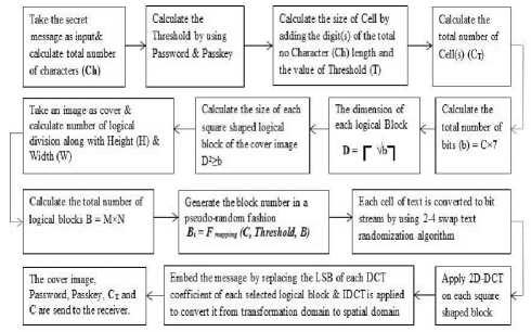
Fig. 1. SP-AM algorithm of embedding of secret message
-
B. Retrieval Method
The retrieval of the secret message from the stego-image is done by following the same algorithm applied for embedding the secret message. All the steps described earlier are repeated for the stego-image at the receiving end except the IDCT method, because there is no need to convert the image from transform domain to spatial domain. After the segmentation of the image, 2D-DCT is applied on the stego-image [6]. Then LSBs are extracted from the DCT coefficients of each logical block. After extraction of the entire bit stream of the secret message, the “4-2 swap” randomization function is applied on it. As this function is a reversible function, it re-arranges the bit stream into its original sequence. Now from this bit stream, the secret message is generated. Fig 2 shows the retrieval method of the secret message from the cover image.
|
Stego Image |
—> |
DxD Block Division |
—> |
Apply 2D DCT |
— |
|
Secret Message |
*--- |
LSBs are extracted from each. DCT |
Fig. 4. Retrieval of a secret message into an cover image
Let I(x,y) denote an 8-bit grayscale cover-image with x = 1,2,…….,M and y = 1,2,…….,N. This M×N coverimage is divided into D × D blocks and two-dimensional (2-D) DCT is performed on each of L = M×N / D2 blocks.
The mathematical definition of DCT is:
Forward DCT:
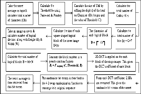
Fig. 2. SP-AM algorithm of retrieval of secret message
-
C. Use of 2D-DCT on Cover Image
The basic idea to hide information in the frequency domain is to alter the magnitude of all of the DCT coefficients of cover image. The 2-D DCT convert the image blocks from spatial domain to frequency domain. The schematic block diagram of the whole process is given in Fig 3 and Fig 4.
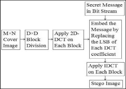
Fig. 3. Insertion of a secret message into a cover image
F(u, v) =
C(u)C(v)∑х=0 ∑;=0 f(x, y)Cos [ ( ) ]Cos[ ( т ) ]
For u = 0,…,7 and v = 0,…,7
= -for к =0
Where C (k) = √
1 ot ℎ erwise
Inverse DCT:
f(x, y) =
∑ u=0 ∑ С(u)C(v)F(u, v)Cos [ ( т ) ]Cos [ ( т ) ] 4 L lb J L lb J
For x = 0,…,7 and y = 0,…,7
-
D. 4-2 Swap Text Randomization Method
The secret message is randomized before the embedding process to impart more security to the entire steganography process. The randomization algorithm is described here.
-
I. The secret message is taken as input & the length of the message is calculated.
-
II. The entire message is segmented into some equal sized cells & padding space if required. Number of cells depends on the total no of characters (Ch) & size of cell(C).
-
III. Evaluate the ASCII values for all characters of each part for the secret message.
-
IV. Modify the ASCII values by using the Passkey & Threshold value.
-
V. Convert each ASCII value into its corresponding 8bits binary value for each character.
-
VI. Swap left most 4bits with the right most 4bits binary value.
-
VII. Swap first two bits with last two bits for efficient randomization for each binary value.
-
VIII. Convert each 8bits binary value into its
corresponding hexadecimal value.
The block diagram of Fig 5 depicts the text randomization process applied on the secret message before embedding.
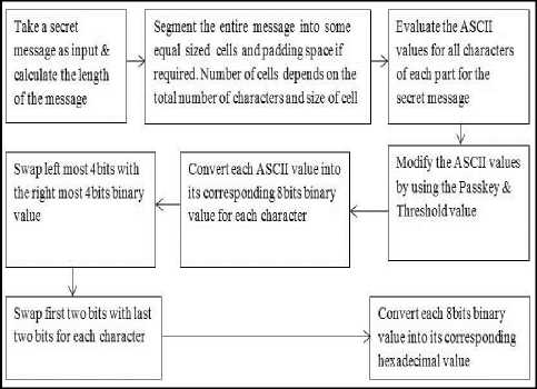
Fig. 5. 4-2 swap text randomization method
-
IV. Implementation Of An Example
-
A. Illustration of 4-2 swap Text Randomization Method
The text randomization method is illustrated with an example in this section. For example consider the secret message as “the university institute of technology at burdwan”.
Here, total number of characters (Ch) = 49
Suppose the calculated Threshold (T) = 7
The size of Cell(C) = 4+9+7 = 20
Total number of cell required = ceiling (49/20) = 3
Min number of character must contain each cell = ceiling (49/3) = 17
To equalize each cell with same number of character need ((17*3)-49) = 2 underscores (_) or spaces( ) to append after the last character of the secret message.
Now all the cells contain equal number of characters.
Cell 1 = “the university in” = 17
Cell 2 = “statute of techno” = 17
Cell 3 = “logy at burdwan__” = 17
Now for cell 1 the message is “the university in”.
The following table shows that after modification of each character the corresponding ASCII values are:
Table 1. Result of 4-2 Swap Text Randomization Method
|
Ch ar act ers |
Modi fied ASC II |
8 Bits Binary Equivalent |
4 Bits Swapped Binary Equivalent |
First 2bits swap with Last 2bits |
Decimal Equival ents |
|
t |
129 |
10000001 |
00011000 |
00011000 |
024 |
|
h |
117 |
01110101 |
01010111 |
11010101 |
213 |
|
e |
114 |
01110010 |
00100111 |
11100100 |
228 |
|
45 |
00101101 |
11010010 |
10010011 |
147 |
|
|
u |
130 |
10000010 |
00101000 |
00101000 |
040 |
|
n |
123 |
01111011 |
10110111 |
11110110 |
246 |
|
i |
118 |
01110110 |
01100111 |
11100101 |
229 |
|
v |
131 |
10000011 |
00111000 |
00111000 |
056 |
|
e |
114 |
01110010 |
00100111 |
11100100 |
228 |
|
r |
127 |
01111111 |
11110111 |
11110111 |
247 |
|
s |
128 |
10000000 |
00001000 |
00001000 |
008 |
|
i |
118 |
01110110 |
01100111 |
11100101 |
229 |
|
t |
129 |
10000001 |
00011000 |
00011000 |
024 |
|
y |
134 |
10000110 |
01101000 |
00101001 |
041 |
|
45 |
00101101 |
11010010 |
10010011 |
147 |
|
|
i |
118 |
01110110 |
01100111 |
11100101 |
229 |
|
n |
123 |
01111011 |
10110111 |
11110110 |
246 |
-
B. Algorithm Used for Embedding the Secret Message
The algorithm used for embedding process is illustrated in this section. Here the calculation of the Threshold value is also shown.
S tep 1
S tep 2
Calculate the Threshold T
T ^ C % 9
T ^ T+ P L
T ^ T % 9
T ^ T + [(9-X)((Pl-Pm)/Pl)]
(Where P L =Original Password Length & P M =Minimum Password Length/Passkey).
S tep 3
Calculate the size of unit (u) by adding the digit(s) of the string length and the Threshold (T).
S tep 4
Calculate the total number of unit (U)
U ^ [С/и]
S tep 5
Calculate Bits per unit (B)
B ^ и х 7 (Each Character is of 7 bits)
S tep 6
Calculate the dimension of each logical block (D)
D ^ \Vb ]
S tep 7
S tep 8
S tep 9
Calculate the Total no. of Logical blocks (B)
B ^ MxN
S tep 10
Generate the block numbers by
B, ^ [(F1 x и‘)mo d(B - i)] + i Where i =1 to n
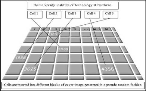
Fig. 6. A realistic view of block mapping process
S tep 11
Evaluate the ASCII values for all characters of each part for the secret message.
S tep 12
S tep 13
Convert each ASCII value into its corresponding 8bits binary value for each character.
S tep 14
Swap left most 4bits with the right most 4bits binary value.
S tep 15
Swap first two bits with last two bits for efficient randomization for each binary value.
S tep 16
Convert each 8bits binary value into its corresponding hexadecimal value.
S tep 17
Get DCT coefficients of all the D x D logical segments of the cover image.
S tep 18
Replace the LSBs of DCT coefficients by the bits of the modified bit stream of secret message generated by the 4-2 swap randomization method. Fig 7, Fig 8 and Fig 9 shows the secret message, cover image and stego-image respectively.
the university in
Fig. 7. Secret text
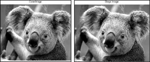
Fig. 9. Stego image
Fig. 8. Cover image
This algorithm illustrates the whole embedding process at the sending end. After embedding the secret message, IDCT is applied [6] on the image to convert it from transform domain to spatial domain and the output stego-image is generated.
-
V. Result Analysis
Experimental result shows that 2D-DCT imparts more reliability and security rather than the LSB substitution technique. Some evaluation parameters are used to measure the performance of the algorithm. The common evaluation parameters are [6] [9] MSE, PSNR, Capacity etc.
Mean Square Error (MSE)
It is defined as the square of error between cover image and stego-image. The distortion in the image can be measured using MSE and is calculated using the following equation
MSE =[ N × N ] ∑^1 ∑ i=l ( ^i- ̅ ij )2 (10)
Where
Xij: The intensity value of the pixel in the cover image.
Xij: The intensity value of the pixel in the stego image.
N: Size of an Image.
Peak Signal to Noise Ratio (PSNR)
It is the measure of quality of the image by comparing the cover image with the stego-image, i.e., it measures the statistical difference between the cover and stego-image, and is calculated using the following equation.
PSNR =10 logw db (11)
Capacity
It is the size of the data in a cover image that can be modified without deteriorating the integrity of the cover image. The steganography embedding operation needs to preserve the statistical properties of the cover image in addition to its perceptual quality. Capacity is represented by bits per pixel (bpp) and the Maximum Hiding Capacity (MHC) in terms of percentage [6].
Experimental result shows that the new approach using DCT coefficient is better than that of the earlier method using LSB substitution technique. Taking the picture of Lena and converting it into a 800×600 dimensional image, the following table shows the MSE values for 3 different block sizes.
Table 2. Experimental Result
|
Image Block Size |
Technique |
MHC (%) |
PSNR (db) |
MSE |
|
150x150 |
LSB |
55 |
39.56 |
32.45 |
|
DCT |
57 |
37.82 |
32.38 |
|
|
200x200 |
LSB |
46 |
38.58 |
32.28 |
|
DCT |
48 |
32.62 |
32.14 |
|
|
400x400 |
LSB |
34 |
35.90 |
28.98 |
|
DCT |
34 |
32.46 |
26.87 |
-
VI. Conclusion
This steganography algorithm implies a multi-level security because before embedding the characters of the secret text message into a cover image using 2D-DCT, the entire text is segmented first into multiple cells and each segment of secret message are randomized at bit level. This randomization or modification is done using a unique function which is a reversible function, i.e. the function is able to re-generate the original sequence from the randomized output. Again all the segments of text are randomly inserted into different regions of the cover image. A bit-stuffing method is used to make the number of characters of each unit equal. A new pseudo-random sequence generator function is used to generate a pseudorandom sequence to embed each of the unit of secret message into the logical square regions or blocks of the cover image in a pseudo-random fashion. Using the same pseudo-random sequence, extraction can be done to get the original message. As mentioned earlier, the input value named Threshold (T) of the pseudo-random sequence generator function depends on the secret password and a passkey known to the two intended parties (sender and receiver) only. As these are secret values, another level of security is also imposed here. This method can be improved again by increasing the strength of threshold value generation function, modifying the method of calculating the total number of characters in each unit of message and also by imposing the randomization function (4-2 swap randomization method) at the character level as well as at the bit level. Here 2D-DCT method is implied instead of LSB substitution technique in this extended version of the previous paper.
Acknowledgement
References A Novel Approach of Image Based Steganography Using Pseudorandom Sequence Generator Function and DCT Coefficients
- Huang W, Zhao Y and Rong-Rong Ni, Block-based Adaptive Image Steganography using LSB Matching Revisited, Journal of Electronic Science and Technology, Vol. 9 (4), 2011.
- Luo W, Huang F and Huang J, Edge Adaptive Image Steganography Based on LSB Matching Revisited, IEEE.
- Transaction on Information Forensics and Security, Vol. 5 (4), June 2010.
- S. Pujari, S. Mukhopadhyay, "An Image based Steganography Scheme Implying Pseudo-Random Mapping of Text Segments to Logical Region of Cover Image using a New Block Mapping Function and Randomization Technique", International Journal of Computer Applications (0975 – 8887) Volume 50 – No.2, July 2012.
- Yang C and Wang S, Transforming LSB Substitution for Image-based Steganography in Matching Algorithms, Journal of Information Science and Engineering 26, 1199-1212, 2010.
- Shiva Kumar K B, Raja K B, Chhotaray R K, Pattanaik S, Bit Length Replacement Steganography Based On DCT Coefficients, International Journal of Engineering Science and Technology, Vol. 2 (8), 3561-3570, 2010.
- T Mrkel, JHP Eloff and MS Olivier."An Overview of Image Steganography," in proceedings of the fifth annual Information Security South Africa Conference, 2005.
- L.Y. Por and B. Delina, "Information Hiding: A New Approach in Text Steganography", 7th WSEAS International Conference on Applied Computer & Applied Computational Science, April 2008, pp- 689-695.
- Analysis of LSB Based Image Steganography Techniques, R. Chandramouli, Nasir Memon, Proc. IEEE ICIP, 2001.
- J.Y. Hsiao. C.C. Chang. and C.-S. Chan. Finding optimal least significant- bit substitution in image hiding by dynamic programming strategy. Pattern Recognition, 36:1583–1595, 2003.
- Potdar V.and Chang E. Gray level modification steganography for secret communication. In IEEE International Conference on Industria lInformatics, pages 355–368, Berlin, Germany, 2004.
- HongmeiTang, GaochanJin, Cuixia Wu and Peijiao Song. (2010): "A New Image Encryption and Steganography Scheme," IEEEInternational Conference on Computer and Communication Security, pp 60 – 63.
- Mahdi Ramezani and Shahrokh Ghaemmaghami. (2010): "Adaptive Image Steganography with Mod-4 Embedding using Image Contrast", IEEE Consumer Communication And Networking Conference.
- Cheng-Hsing Yang, Shiuh-Jeng Wang, "Transforming LSB Substitution for Image-based Steganography in Matching Algorithms", Journal of Information Science and Engineering 26, 1199-1212 (2010).
