A Novel Heat Pipeline Design for North and Northwest Continental Urban and Rural Areas

Author: Evgeny B. Benenson
Journal: Доклады независимых авторов @dna-izdatelstwo
Section: Construction
Article in issue: 7, 2008.
Free access
This article discusses the state of urban and rural heat pipeline networks of various climatic regions. An emphasis is made on vulnerability of the current heat pipeline design, and necessity for some stretch design is being proved. Novel design of various heat pipeline elements is given a fairly detailed consideration; several three-dimensional views of the said elements are also shown. Examples of other countries’ heat pipeline structures are given. The design of the prefabricated elements of the project brought to discussion is not given in full detail. A complete version of the standard-format project (containing parts and units thereof) is available upon potential customers’ request. It is important to note that in addition to hot water supply, that is, heat pipeline’s routine application, the project is specific for its substantial benefits: as related heat-engineering calculation shows, superficial heat loss in the pipeline under discussion is only 23 wt/sq m, 5 times smaller a figure in contrast to that of conventional structures (119 wt/sq m) currently in use. In terms of fuel equivalent (within the price scale of 1999-2000- ies) this enables to cut expenses for per-kilometer extra heat boosting of return network water by $2,000-3,000 annually. Besides, 70-year-long trouble-free operation period is to be taken into consideration, too.
Short address: https://sciup.org/148312135
IDR: 148312135
Text of the scientific article A Novel Heat Pipeline Design for North and Northwest Continental Urban and Rural Areas
This article discusses the state of urban and rural heat pipeline networks of various climatic regions. An emphasis is made on vulnerability of the current heat pipeline design, and necessity for some stretch design is being proved. Novel design of various heat pipeline elements is given a fairly detailed consideration; several three-dimensional views of the said elements are also shown. Examples of other countries’ heat pipeline structures are given.
The design of the prefabricated elements of the project brought to discussion is not given in full detail. A complete version of the standard-format project (containing parts and units thereof) is available upon potential customers’ request. It is important to note that in addition to hot water supply, that is, heat pipeline’s routine application, the project is specific for its substantial benefits: as related heat-engineering calculation shows, superficial heat loss in the pipeline under discussion is only 23 wt/sq m, 5 times smaller a figure in contrast to that of conventional structures (119 wt/sq m) currently in use. In terms of fuel equivalent (within the price scale of 1999-2000-ies) this enables to cut expenses for per-kilometer extra heat boosting of return network water by $2,000-3,000 annually. Besides, 70-year-long trouble-free operation period is to be taken into consideration, too. An unbiased evaluation followed by a positive resolution upon the present project by various administrative and governmental bodies or private contractors gives way to the following opportunities:
-
1 . Development of high-tech production facilities or renovation of the operating ones to manufacture block units and components for efficient heat conduits;
-
2 . Availability of governmental or private investments as operation of the high-tech heat conduits is a definitely profitable business (see item 4 below);
-
3 . New jobs as a consequence of virtually limitless scope of work to do;
-
4 . Unprecedented substantial benefits from operating and controlling the high-tech heat conduit networks involving virtually no overhaul-related expenses whatsoever for a long time;
-
5 . A rapid and efficient invigoration of the municipal engineering as well as the entire socio-economical situation in a city or a village.
Contents
-
А. State of the Art
-
B. Offer Details
-
С. Description of Design and Materials Properties
-
D. Engineering Calculation Data
-
F. Terms of Embodiment References
-
A. State of the Art.
The urban underground hot-water and heat supply pipelines currently in use seem to be unable to provide reliable long-term operation under minimum heat loss even though built in strict compliance with construction rules and specifications. This can be explained by the fact that simplest possible engineering solutions were applied in heat conduit construction predetermined by shortage of facilities, materials, and time. Besides, no other option seems to have been known by then. While constructing a heat piping climatic conditions, frost penetration, soil mobility, and wandering subterranean waters of the north and northwest regions have not been given due regard. These prerequisites taken together come as cause of emergency conditions and shorter service life. It is only a year’s time to observe numerous spots showing complete destruction of the insulation blanket, threatening pipe corrosion, and lower supports flooded with ground water.
Under the standing rules and standards for heat conduits there is no way for altering the situation. Expansion of emergency job scope will remain as endless trouble on an yearly basis. What is more, related expenditures will only be increasing in the course of time.
The western countries employ a tube-in-tube design of the heat conduits where cylindrical inter-tube space is filled with foamed polyurethane to form a heat insulating layer upon solidification. Both central and external tubes are made of a polymer. The design is attractive for its apparent simplicity; there is no need of any slide leg at all, and the tubes do not corrode. This design is given a large-scale dissemination. However it should be noted that the above design is only applicable in the moderate climate zones preferably in horizontal and straight sections of the piping. It should also be remembered that polymer tube connection (lineup and gluing) technique is not easy requiring strict abidance by specifications whatever the conditions . No displacement of the tube edge resulting in cracking is at all admissible. Meanwhile the tubes proper are exposed to the threat of crack-forming at the temperatures ranging within -15 -20оС.
With regard for urban heat supply network configuration complexity, harsh climatic conditions involving sharp temperature differences in the northwest regions and deep frost penetration in the extreme north areas, absolute reliability of the polymer-based heat piping under the above conditions is arguable.
There is a trend of developing independent heat supply systems. Both efficacy and usability of these systems are irrefutable, however their advent and full-fledged development along with complying with relevant ecological requirements are only possible under specific territorial and economic conditions which are still be to be established . This is the matter of time.
Besides it stands to reason to state that through 21-22 centuries and on, the central heating systems will retain their usability.
Developing a novel heat conduit design is an absolute must to radically reduce urban and rural heat conduit maintenance costs to completely exclude the maintenance or repairs for a long period of operation , reduce expenditures on fuel of every kind, and finally, save time in the course of economic development.
However, to these ends, construction concept for both heat conduit components and urban heat piping is to be radically changed (see Description of Design and Materials Properties ...).
For the time being, a production project is available to describe now the 2nd version of the urban heat conduits’ components for harsh climatic conditions.
-
B. Offer Details
An alternative design of the conduits with pipes ranging 76-325mm in outer diameter is offered to enable the following :
-
1. A complete protection (confinement) of the space of hot water conduit from penetration of hostile environments (ground water and the like) using a specially designed concrete shell.
-
2. Minimum heat loss (23 wt/sq m) and heat conduit’s external temperature of 8,3 - 9°C under the heat carrier temperature as high as 100 - 120°C and environmental temperature of 0°C (cf.: conventional heat conduit’s external temperature is 29°C (provided the latter is in good working order); and heat loss is as big as 116 wt/sq m under the same conditions).
-
3. Excluding a possibility of heat conduit freezing following a sharp temperature decrease or a disconnection from a hot water supply in winter (or because of an emergency).
-
4. A pre-designed urban heat conduits’ ability of faultless operation for a minimum spell of 70 years . The said long-term trouble-free operation is primarily dependent on both engineering and mechanical state of the heat-carrying tubes as well as quality of welded joints which can be monitored when connection of the components and units is complete.
-
5. Excluding repairs in the coming years of heat conduit operation. Here, an operating heat conduit of 219–273-mm in diameter is capable of reducing per-annum fuel expenditures by at least $2000 for every 1,000 m of its length (the figures are given for one singledirection heat conduit in the price scale of 1999–2000-ies).
-
С. Description of Design and Materials

Along with application of fundamental laws of thermodynamics, calculation methods of heat flow in a closed annular space appearing in formulae proposed by Eckert and academician A.M. Mikheyev (free-convection closed-space dissipation [1] ) were used in developing the project.
Structurally, the design of every components of the heat conduit — tees, off-takes (bended tube sections), collectors, and straight sections — is virtually the same. Figures 1, 2, 3, 4 below give a 3D presentation of some of the heat conduit’s components.
The present heart conduit’s design is specific in that the heat-carrying tube proper (hot water tube) is not covered with an insulating layer (see Figures 1, 2, 3, 4).
A cast concrete sheath specific for high moisture and crack resistance, freeze-thaw durability and enhanced strength (1.5-1.65 times as much as compared to conventional structures) comes as main carrying and protective structure . Composition of the concrete sheath includes С3 plasticizers or complex modifying agents; here, consumption of cement is reduced by 20%, according to manufacturer’s data. Internal cylindrical surface of the sheath is to be smooth with no coarse or even average grade of finish. Some (special) conditions enable to use an external surface of 2-3mm-thick plastic tube as a base surface in casting of the concrete sheath. When both forming and normal hardening of the concrete is complete, the sheath has the following specifications: water tightness: W14; ductility: П5; freeze-thaw durability: Р400; strength: 53 MPa (at the age of 29 days) and 37 MPa (at the age of 7 days). The sheath’s outer surface can be of cylindrical shape, while the inner surface can be square or square-unit one (for 2, 3, or 4 pipelines).
The sheath’s inner surface is covered with a cylindrically-shaped thermal insulation layer with thickness corresponding to a specific thermal design (60-50 mm in the selected version). Fiberglass having heat conductivity factor of 0,035 wt/(М*°C) or a foam-insulating plastic having heat conductivity factor of 0,035 – 0,04 wt/(М*°C), are used as heat insulators. The heat-insulating layer is formed consecutively form separate cylinder-shaped units 200, 300, 500mm in length (depending on specific nominal size or format). The butt ends are cone-shaped (90о) to ensure tighter coupling. Other reasonable versions like filling preliminarily limited cylindrical space with a thick foamed polyurethane 0,044 wt/(М*°C), are definitely welcome.
A steel tube with anticorrosion coating on both inner and outer surfaces is positioned centrally. The tube is kept in its central position by means of several special slide legs (2 -3 pcs. per a 8-9-meter-long straight section); the number of legs is defined according to specific design and related calculations. These are integrally cast legs made of a heat-resistant polymer containing a metal insert from the side of sliding surface. This polymer component withstands heat exposure of 90-140°C; material’s estimated allowable stress is within 80-160MPa; density is 0.92-1.78 g/cub cm. The legs rest on the inner surface of the concrete sheath (see Fig. 4), and are mounted in a set order jointly with installation of the heat-insulation units.
Some air space serving as additional heat resistance factor is formed between external surface of the steel tube and inner surface of the insulation layer as a result of assembling. Layer’s effective height is to be defined through a corresponding thermal calculation.
Every thermal broadening of the steel tubes within the sheath with regard for thermal variators’ design is duly taken into account.
Installation of specially designed steel expansion pipes is envisaged at the junction points of old and new pipelines to prevent moisture from stealing into new heat conduit’s environment.
The legs (see Fig. 1) positioned at the site of pipe-laying ensure general requirements as to pipeline’s proper positioning. The legs’ design adds to easier and faster components’ reciprocal positioning during onsite connection. Specially designed mini-sized cylindrical piles coming as part of the legs’ design are oriented perpendicular to the legs’ horizontal axial plane to prevent ant displacement or skewing in other crossing planes of the heat conduit’s central axis thereby improving heat conduit’s overall stability.
Other specific designs of the heat conduits can also be made. However, formation of closed circular space around the heat-carrying tube, that is, the core principle of the present concept is to be left unchanged.
A STRAIGHT SECTION: GENERAL VIEW
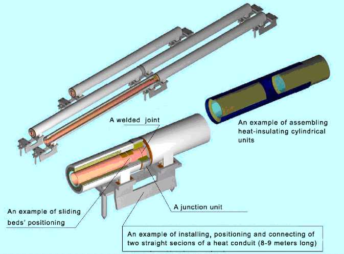
Fig. 1
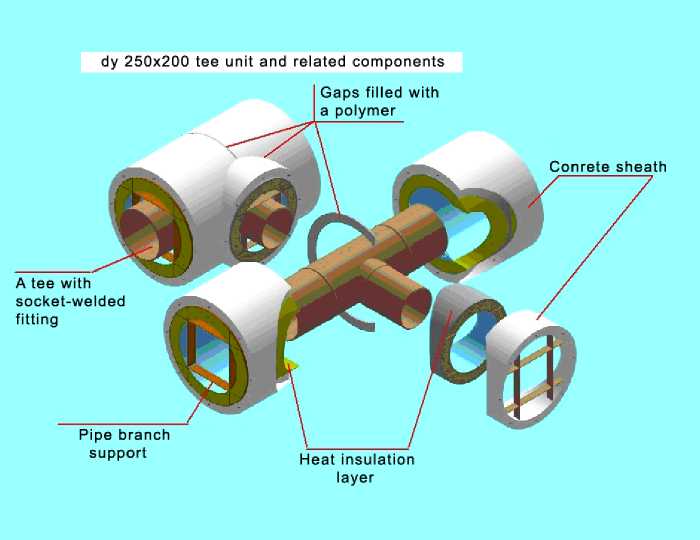
Fig. 2
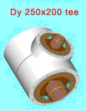
Fig. 3
Sliding bed’s position at the end of cast concrete sheath
A fiberglass layer
Cast concrete sheath
Tube 0 273 x 7
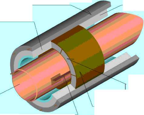
A fiberglass layer
Filling of six sections of the bed with crumbs of fiberglass or foam polyurethane
Bed
Tube’s bilateral I torque limiter
Fig. 4
-
D. Engineering Calculation Data
Charts shown below demonstrate the results of thermal engineering calculations of the new and operating structures of underground hot water conduit. Here, a comparative minimum heat loss value in two different structures and efficiency of the novel structure offered are shown.
Charts of comparative temperature dependencies and superficial thermal losses in two types of heat conduits under ambient temperature variation
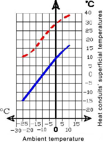
Presentation of dependencies of thermal properties in conventional structures

-15
-5
-30 -20 -10
О 10
wt/sq
ISO
IIO
GO
Ambient temperature
m
CO co о
CD
CD
CD
E
CD
co
О
CO
w
О
co
Presentation of dependencies of thermal properties in heat conduits of novel design
F. Terms of Embodiment
All parts, elements and units of the hear conduits are to be manufactured in plant’s conditions. To these ends, development of dedicated production facilities is necessary. There should be no place to a doubt of a possibility of having the said facilities equipped correspondingly. There is related experience in developing and manufacturing of cylinder-shaped heat-insulating units complying with the present offer’s specifications. There are related technology and experience of manufacturing the cast concrete sheaths corresponding to the present offer’s specifications. And finally, there must be no doubt as to designer’s ability for developing appropriate building berths, master plates and machinery to be built for further operation at workshops. The equipment should be completely faultless in terms of heat conduit’s parts manufacturing and erection phases. A production unit can be selected proceeding from the following two conditions:
-
1. Manufacturing of parts, metal structures, circular heat insulation units, concrete sheaths and beds as well as assembling of all the components and units of the heat conduit is to be made at dedicated workshops of the same production plant.
-
2. Manufacturing of parts, metal structures, circular heat insulation units, concrete sheaths and beds is made by a sister production unit. A dedicated assembling company carries out all kinds of erection works using the parts and units manufactured by the sister production units.
The equipment of the production units should be in keeping with a selected production sequence. Manufactured components and units are transported to a prepared site of heat conduit laying. On-site works include:
-
1. Placement of components and units onto special setting piles which apart from complying with general specifications also serve for easier and faster components’ reciprocal positioning during on-site connection.
-
2. Welding of steel tubes’ components and units to at the point of their connection to sliding beds.
-
3. Non-destructive ultrasonic flaw detection in welded joints.
-
4. Testing of the assembled section of the heat conduit.
-
5. Placing of heat-insulation ring and sealing joints units using a special technique. The technique enables a safe binding of the sealing ring with the bulk of the concrete sheath of components and units eliminating a threat of crack formation at the connection points.
Provided a well-reasoned engineering preparation is done, the rate of heat conduit laying is 3-5 times faster than the one made following conventional construction sequence.
