A novel method for crack detection in steel cantilever beam using wavelet analysis by combination mode shapes

Author: H. Rouhollah Pour, J. Asgari Marnani, A. A. Tabatabei
Journal: International Journal of Image, Graphics and Signal Processing @ijigsp
Article in issue: 4 vol.10, 2018.
Free access
The first step in Structures Health Monitoring (SHM), are determining the location, intensity and type of damage in structures. Crack is a damage that often occurs in structural elements and may cause serious ruptures in the structure. One of the important approaches is the wavelet analysis of vibration modes structures. In this study, it has been performed the crack detection method in steel cantilever beam structure, using an optimized wavelet-based model. The wavelet analysis has been performed based on the higher orders of the structure’s mode shapes. The results show that the proposed method is able to accurately detect all kinds of cracks, in which the cracks location are variable. In this study also, cracks with length of 20%, 10%, 5% and 2% of the beam’s depth have been considered and one of the most prominent results is introducing a method for detecting robust and environmental noisy cracks. The proposed method is capable of accurately detecting crack in the cantilever beams in noisy conditions about 20 dB of SNR.
Structures Health Monitoring, Cantilever Beam, Wavelet Analysis, Crack Detection, Mode Shape
Short address: https://sciup.org/15015950
IDR: 15015950 | DOI: 10.5815/ijigsp.2018.04.01
Text of the scientific article A novel method for crack detection in steel cantilever beam using wavelet analysis by combination mode shapes
Published Online April 2018 in MECS DOI: 10.5815/ijigsp.2018.04.01
In context of Structures Health Monitoring (SHM), the discovery of damage in structures has a special standing. The first step in rehabilitation of structures’ behavior, is determining the location, intensity and type of damage in structural elements. Cracks are a damage that often occurs in structural elements and may cause serious collapse in the structure. Many non-destructive methods are discovered based on the changes in the dynamic properties of the structure (frequencies, mode shapes, transfer functions, etc.), which are caused by damage. According to vibrations dynamics, analysis of these changes can make it possible to detect cracking. Dimarogonas et al, as a preliminary idea, modeled the crack as a localized softness, experimentally and studied the equivalent hardness [1]. Gudmaunson [2], by using the chaotic-based method to predicted the changes in the natural frequencies generated by the cracks in the structure. Rizos et al, proposed a method for use to measure the amplitude of mode shapes at two points in the cantilever beam, which is shaken in one of its natural modes [3]. Such studies have been continuing as important challenges in this media. The first parameter used to diagnose the health of structures is the natural frequency of the vibration in which the natural frequency of the structure is obtained locally using special equipment and then compared with the normal frequency of the health structure. Farrar et al. [4], investigated the damage of the bridge by identifying changes in the natural frequency. They found that there was a slight change in frequency when the severity of one of the main controllers was significantly reduced. The natural frequency of the structure is a general characteristic of the structure and it is only capable of detecting structural failure and will not give any information about the location or the severity of the failure. Another method is to use the mode shape fashion. The West's research, [5] was one of the first investigations to detect a failure using a mode shape form without using the finite element modeling. In their research, the correlation between the same structure, before and after loading, is determined and the location of the failure is recognized as a comparison. The Fox study showed that West's method for detecting some failures has defects, and therefore suggests using more points to measure the mode shapes [6]. Ratcliffe proposed the other dynamic characteristic that has been considered the curvature of the mode shape. The mode shape curvature actually represents the second derivative of the mode shape. The curvature is related to the strain of the surface of the test member, and therefore, with changes in stiffness due to the failure, the curvature mode will also be changed locally [7].
The Fourier transform provides information about the frequencies in a signal. However, it does not provide any information since the occurrence of a specific frequency. A useful method for this purpose is to analyze wavelet signals that do not have this problem. Wavelet transforms can detect many unknown aspects of information that other signal analysis methods can't detect. The main idea of detecting damage by a wavelet is that the damage to the structures can create singular or single points in the form of a mode shape of the structure. The study of
Banks and colleagues [8], was one of the first published papers on crack discovery using the wavelet method. This paper presents an attempt to identify cracks in a beam with a simple support. Loutridis et al, identified double cracks by analyzing the position of the cracks as the main vibration mode of a double cracked cantilever beam using continuous wavelet transformation [9]. They determined the position of the cracks, by displacement response calculation of the considered beam using wavelet transform. Wavelet transform computed for scales 1 through 25 with sym4 wavelet function. It was found that wavelet transform coefficients exhibit high values at the cracks’ location. Sherif et al, using a wavelet transform and piezoelectric stimuli to detect collapse in bridges. In this method, data from vibration signals were used to identify the failure in a steel bridge of railway lines and results of the mathematical and empirical model of the bridge were also compared [10]. Studies by Jeon et al, using the wavelet analysis, introduced a crack detection method in a steel frame structure. This method is based on an algorithm for image processing by wavelet analysis that detects crack images of the oxidized material on elements [11]. Yong et al, discovered the location of cracks in beam structures by the combination of wavelet analysis and fractal dimension. They used a wavelet method to analyze the mode shape of the crack and found that small cracks can't be detected and require the use of fractal dimension. Also they performed their study on the cantilever beam and validated their method by simulating the effectiveness of the method [12]. Abdulkareem et al, investigated a diagnosis of damage in a steel plate. They used a combination of modes healthy structures and faulty structures and used the analysis as a twodimensional wavelet transform method [13]. Most of the reported wavelet transformations are devoted to the first mode shape, and even to the three of first modes. This is because the lower-order mode shape is much easier to achieve than the higher order. Okafor et al, examined three laboratory forms of modes and six forms of numerical mode shape for a cantilever beam by wavelet analysis. They conclude that the first and third transverse sections of the damage site are clearly shown, but the second form of the mode is unsuccessful, since damage occurs in the empty space passing through zero for the second mode shape [14]. Another study showed that damage may occur in places with poor sensitivity for certain modal forms. Consequently, neither the lower mode forms nor any of the higher single modes can be considered as useful for detecting the damage by default. They also stated that accessible modes or practical reflective forms should be reviewed [15]. In a numerical study by Castro et al, the quality of the damage detection was studied based on the order of vibrational modes, which formulated the modes order effect on damage detection. They stated that higher-order modes are better suited to detect damage [16]. Modal analysis in high degrees due to technical constraints has been extremely difficult until recently, while high-level modes contain useful information. With the advent of laser shakescanning, it was possible to analyze the higher degrees of modes shape. The wavelet analysis has been done on damage detection in a steel cantilever beam by examining higher degrees of mode shapes. He studied the efficiency of wavelet analysis by higher-order mode shapes for the beam and by examining the first eight modes, verified the effectiveness of continuous wavelet analysis [17]. Naresh et al, studied simulation of up to 10 mode shapes in this sector [18].
According to the literature review of this field, although various studies have been carried out by researchers in this field, the methods for detecting cracks in structures such as cantilever beam have been optimized, so that present studies have a large dispersion. Researchers of this domain have reported different wavelets and sometimes they have also used conflicting features. In the present study, it has been provided a method for detecting cracks in the structure of a steel cantilever beam, using a wavelet analysis and optimized it based on mode shapes. What kind of wavelet function and method for tracking cracks in the beam are optimal and provide better results, also have been examined. The purpose of this study was to provide a non-destructive method for crack detection using optimal wavelet analysis on the cantilever steel structure by determining the type of optimal wavelet analysis. The application of this research results is in all structural industries such as constructions, tunneling, oil and gas installations, etc. Finally, we are going to implement a basic reference method that analyzes the wavelet on the higher mode shapes on the beam and then, will find out the basic problems of this method to provide a total solution. In the next step, it was evaluated in different types of cracks in the cantilever beam, cracks with different distances from the support, multiple cracks on the structure, Crack with depth of 20%, 10%, 5% and 2% of the beam height and check the crack detection in noisy conditions.
-
II. A Review of Wavelet Analysis
Most of the reported signal analysis methods are based on Fourier transform, which transforms each signal into an infinite group of complex exponential functions, each of which has different frequencies. In fact, the Fourier transform takes a signal from the spatial domain to the frequency domain, so in this transformation it is not possible to detect the time (space) which a special occurrence. In order to correct this defect, a method called wavelet analysis was presented. The wavelet analysis specification is that wavelet analysis can show the location of breakpoints and singular or single points in a function (the main idea of detecting damage by a wavelet). The wavelet of a given function is assumed to be with a mean of zero, and the expansion is in terms of the transitions and the change in the scale. The wavelet transform can show the important characteristics of the signal in the time-frequency domain.
-
A. Continuous Wavelet Transform (CWT)
Assume that ψ (t) is a function with real or complex value in the space of square-integral functions and with the mean zero. We call the function ψ (t) as a wavelet if the following conditions are true:
+»
V( t ) dt = 0, ||T( t )||= 1 (1)
—да
The wavelet transform analysis function with the scale S and the transfer b is computed by:
+” 1 * t -b
WF ( b , s ) = f ( t)^ V (----) dt
-” 5s 5
Where the * represents the mixed conjugate [19].
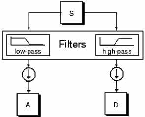
Fig.1. Filtering process in DWT analysis
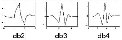
Fig.2. Three examples of Daubechies family wavelets [20]
-
B. Discrete wavelet transform (DWT)
In discrete wavelet analysis, we often talk about approximation and detailed coefficients. The approximation coefficients have a high scale and low frequency signal components. The details have low scale and the frequency components are high. The filtration process, at the basic level, is as shown in Fig. 1. The main signal S passes through two complementary filters, and after sampling, it converts to two signals, which these filters are made up of wavelet functions [20].
-
C. Wavelet Functions
For wavelet functions, ψ, various suggestions such as Haar, Morlet, Mexican hats, are presented. Ingride Daubechies, one of the most prominent researchers in the wavelet domain, has invented a wavelet function known as orthonormal wavelet; the name of the wavelets family is written in dbN, where db represents the wavelet's name and N is the wavelet order. In Figure 2, you will see three wavelet types of the Daubechies family as samples. These wavelets have properties that have led us to be used to conduct our current research [21-24]. These characteristics are: time-invariant, fast calculations, sharp pass bands in a filter that minimizes the effects of the boundary between frequency bands.
-
III. Detecting the Cracks by Wavelet Analysis on Higher Vibrational Modes
The general technique for crack detection is as following: for a given one-dimensional signal (for example f(x), that here it is the shape of a cantilever beam), the wavelet transform can find the singular points in the f(x). The location of the damage is obtained by finding the points of the continuous wavelet transform module that is maximal. The wavelet transform modulus (WTM) is equal to the absolute magnitude of a continuous wavelet transform. Choosing the appropriate wavelet function type is vital for effective application of wavelet analysis in identifying damage. Using wavelet functions that produce the highest number of coefficients close to zero makes it easier to identify damage. In this case, strong singular values are observed only in the places where the damage occurs. For example, Gaussian wavelets were tested in [17], which could be the best candidates for damage detection by transforming a continuous one-dimensional wavelet. In that research, numerical simulations were carried out on the first eight mode shapes. The CWT, by the Gaussian wavelet family, is computed on the eight of first mode shapes of the beam.. The selected wavelet functions produce the most near-zero wavelet coefficients and generate non-zero values at the damage location. The crack will appear on the WTM curve for the eight mode shapes. We will continue to implement this technique and present its drawbacks and provide a solution.
-
IV. Implementation of the General Crack Detection Technique
The profile of the underlying cantilever beam is similar to the cantilever beam modeling in reference [17], which both Euler-Bernoulli modeling and practical experiments have been studied, and their results can be considered as a benchmark for the current research results. The profile of the cantilever beam is as follows: a steel cantilever beam in accordance with Fig.3, and its parameters as a 198.25GPa elastic modulus, a mass density of 7718.59 kg/m3 and a Poisson factor of 0.3. The cross section is square with a surface of 1cm2, and length of the beam is 40cm. In addition, the depth of cracking on the beam is expressed in percentage of beam height. In the present study, we use two softwares ABAQUS and MATLAB [20, 25].
0.1 0.2 0.3 0.4
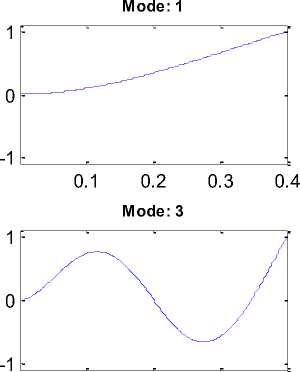
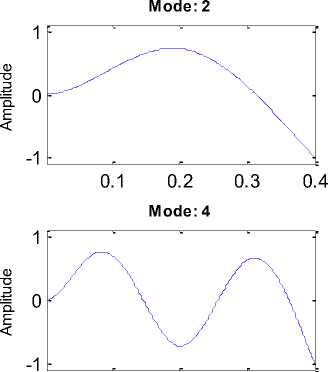
In order to model the cantilever beam and solve the problem, we use the finite element method with the ABAQUS software. To do this, we created and perform mesh process for beam using the software. Then, we obtained the eight first mode shapes (natural frequencies) by calculating eigenvalues by the LANCZOS method. The crack is placed with a depth of 20% of the beam height, i.e. a crack with a depth of 2 mm in the beam. The crack distance from the support-end is xd=0.201m and the crack width is also 0.002m. Fig.4. shows the modeled beam. We first got the mode shapes for the cracked beam. Fig.5 shows the displacement movements obtained from the beam by vibration in the first to the eighth modes. It is observed that in some mode shapes like mode eighth in the place of the existence of a crack, a very small singular point has arisen that indicates an occurrence at that point where wavelet analysis can detect it. After having mode shape, they are delivered as a signal to be analyzed with
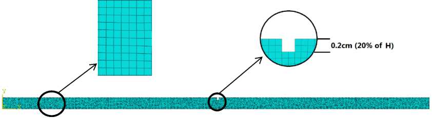
Fig.4. A beam with a crack with depth of 0.002m (equivalent to 20% of the beam height) at a distance of x d =0.201m from the support end.
0.1 0.2 0.3 0.4
Mode: 7
-1
CD
-1
Mode: 8
о
0.1 0.2 0.3 0.4
0.1 0.2 0.3 0.4
Beam Length (m)
Beam Length (m)
Fig.5. Eight mode shapes for a beam with crack at xd=0.201m from the support.
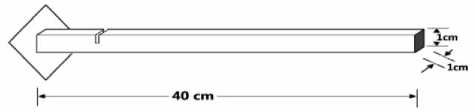
Fig.3. the dimension of underlying cantilever beam
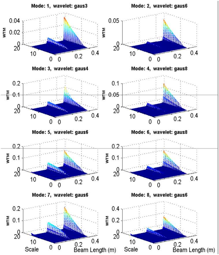
Fig.6. The WTM curves obtained for the first to eighth mode shapes for the cracked beam
According to Fig. 6, the results of Wavelet analysis showed that increasing the amount of WTM amplitudes in the crack location indicates a good location recognition that was better in the seventh mode analysis than in others. So far, we have done the simulation in accordance with the usual technique in the articles in this area.
-
V. The drawback of the CWT Method in General Technique
With general technique, continuous wavelet analysis was used on the first to eighth mode shapes signals [17]. But their methodology has challenges that must be taken into consideration. They used the Gaussian family of wavelet function in the continuous CWT transform method, and according to literature in this area, that wavelet family had the best results in detecting cracks in cantilever beams. It should be noted that the family of Gaussian wavelet functions itself contains various functions such as gaus1, gaus2, etc. In fact, the Gaussian function is derived and new functions are created.
We analyzed signals of mode shapes with different families of wavelets by the CWT method, and we confirm the previous reports, which the best results are produced with the Gaussian family. But there are some important points in this regard.
First, in a time-consuming process, for each mode of the first to eighth, it should be examined separately to determine which type of function is appropriate for the Gaussian function family. For example, according to Fig.6, we checked for the first mode of the whole Gaussian family and after analyzing the signal, we finally realized that the gaus3 wavelet has the best result. We tried again for the second and found that the gaus6 wavelet had the best answer, and so on. But, just with change the place of crack or change its depth, that function of the wavelets does not suit the correct answer; and again, all Gaussian functions must be observed to see which function is suitable for the mode shapes. This scenario point is a fundamental problem. Because we were already aware of this example, and we knew that the cantilever beam was defective and cracked, and knew where it was, we watched different wavelets to see which one finally finds the cracks. In general, such a way does not respond if the cracks and its location are unknown and we do not know and want to find it. In the meanwhile, it may be defective, and basically a good wavelet for that mode is not found at all. Interestingly, this family of wavelets (Gaussian) has had the best response and results. Therefore, finding the appropriate wavelet analysis method is an important issue to consider. Next problem is about crack detection in which mode shape. With the change of the cracks in the beam, it is observed that any mode shape has one or more regions in which the sensitivity to damage detection is lost by CWT. The reason for the presence of blind areas is that these places are in places where the size of the shape of the mode is zero (the place of the Mode nodes). Higher order of mode shapes have more blind points. Therefore, it can be said that higher modes, although they are more sensitive to damage and detect them better, but with the disadvantage that there are more blind spots for them. Therefore, because a crack may not affect some mode shape, in order to detection of cracks, the wavelet analysis of all the mode shapes must be checked. According to the above, finding the appropriate wavelet analysis method is an important issue to be addressed.
At the endpoints of the beam, in which the CWT wavelet analysis points create large coefficients that may be identified with a mismatch. This topic is referred to the turbulence problem of the terminal region of the signal. As mentioned, continuous wavelet transformation is defined as the integral of the multiplication of the wavelet function in an indefinite length signal function, whereas the mode shape that is evaluated as the input signal is limited in length. As a result, distortion occurs at the extreme edges (at the base of the support). In this situation, the wavelet coefficients at the end of the signal will be relatively large, and these points should not be identified as damage locations. This issue is not problem of our study and can solve easily with some tricks such as extrapolation which was discussed in some studies [17].
-
VI. Proposed Method for Crack Detection by Wavelet Analysis of Mode Shape
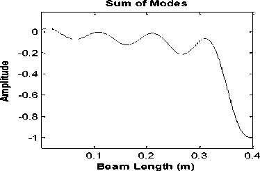
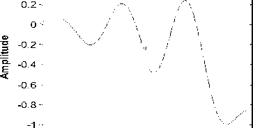
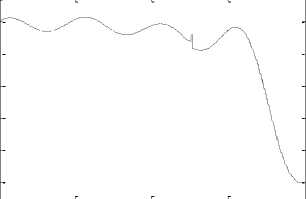
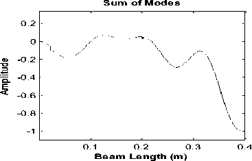
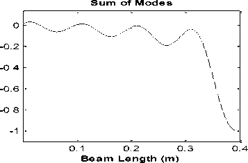
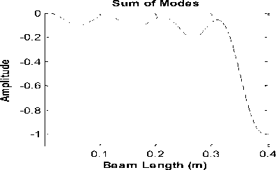
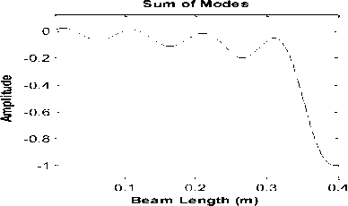
Based on the results, we propose using a DWT method and a proper family wavelet function instead of applying the CWT method. A new approach is proposed in this section. Instead of survey the entire mode shapes, we use this method; according to Fig.7, first, we obtain the mode shapes and normalize them in range 1 and -1. Then, the sum of all the mode shapes is computed. In replace of the eight signal categories, we get one signal that we apply DWT for it. Thus, regardless of which crack appear in which mode shape, it will appear in a single category of final wavelet coefficients. So, firstly, there is only a single mode shape, then it is necessary to find only one wavelet function. Secondly, the cracks can be detected by the DWT of a single mode shape as the final result, and it is not necessary to check all the primary mode shapes.
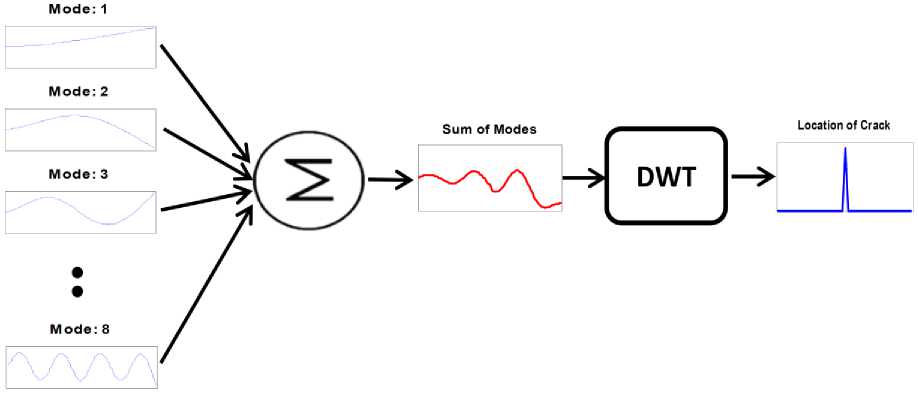
Fig.7. Proposed method for detection of cracks by combining the mode shapes
For the effective use of the discrete wavelet transform method (DWT), it is necessary to use a family wavelet function. To this end, we propose the functions of the wavelet family of the Daubechies [21]. We recommend this family after repeated surveys and simulations on different cracks and their success. It should be noted that bringing the results of detecting the cracks on the beam for all types of wavelet families, within each family of functions, is outside the scope and requirements of this paper, but it should be noted that we have several types of discrete wavelets in various simulations have been investigated frequently and we have seen that the Daubechies family has made the best results to others. So, we chose it as the main wavelet.
-
VII. Simulation Results
In this section, we present the simulation result of the proposed method in several different detection situations.
-
A. Detecting crack at different intervals
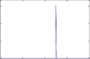
In order to demonstrate the efficiency of the method, we create a crack at a depth of 20% of the beam height, is a crack with a depth of 2 mm in the beam. We perform our proposed method for four positions of crack for examples. The distance of crack from support of beam is at 4 sites: x d1 =0.021m, x d2 =0.201m, x d3 =0.251m and x d4 =0.381m. As shown in Fig. 8, the position of crack is clearly seen, which is well illustrated by the success of the method in crack detection. It is no longer necessary to check the wavelet analysis of the single modes and can easily identify the position of the crack from a final wavelet analysis form.
-
B. Detection of more than one crack
0.14
0.12
0.1
0.08
0.06
0.04
0.02
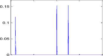
In order to study the efficiency of the method in detecting more than one crack simultaneous on the beam, we simulate other states. Firstly, we create two cracks at a depth of 20% of the beam height, i.e. cracks with a depth of 2 mm in the beam. The first crack distance from the support is xd1=0.021m and the crack width is also 0.002m. The second crack is at xd2=0.201m with the same width as the previous one. As shown in Fig. 8, this simulation shows that the detection of cracks is well done. In the second simulation, we create three cracks at a depth of 20% of the beam height, i.e. cracks with a depth of 2 mm in the beam. The first crack distance from the support is xd1 = 0.021m and the crack width is also 0.002m. The second and third cracks are at xd2=0.201m and xd3=0.251m, respectively. As shown in Fig. 9, this simulation also shows how well the cracks are detected.
DWT coefficients (Location of Crack)
0 0 0.1 0.2 0.3 0.4
Beam Length (m)
Fig.8a. Detection of crack at x d1 =0.021m from beam support using the proposed method

Sum of Modes
DWT coefficients (Location of Crack)
0.15
0.4
0.1 0.2 0.3 0.4
Beam Length (m)
0.1

0.05
0 0.1 0.2 0.3 0.4
Fig.8b. Detection of crack at x d2 =0.201m from beam support using the proposed method
Beam Length (m)

Sum of Modes
DWT coefficients (Location of Crack)
-0.2
-0.4
Е -0.6
-0.8
-1
0.15
0.1 0.2 0.3 0.4
Beam Length (m)

0.1
0.05
0 0.1 0.2 0.3 0.4
Beam Length (m)
Fig.8c. Detection of crack at x d3 =0.251m from beam support using the proposed method

Sum of Modes
DWT coefficients (Location of Crack)
0.2
0.1 0.2 0.3 0.4
Beam Length (m)
0.15

0.05
0.1 0.2 0.3 0.4
Beam Length (m)
Fig.8d. Detection of crack at x d4 =0.381m from beam support using the proposed method

DWT coefficients (Location of Crack)
0.15
0.1
0.05
0 0.1 0.2 0.3 0.4
Beam Length (m)
Fig.9a. Detection of cracks in the beam with two cracks at x d1 =0.021m and x d2 =0.201m

Sum of Modes
DWT coefficients (Location of Crack)
Amplitude Amplitude
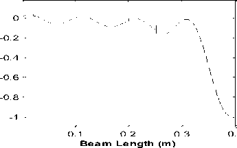
Fig.9b. Detection of crack in the beam with three cracks at x d1 =0.021m, x d1 =0.201m and x d2 =0.251m
0 0.1 0.2 0.3 0.4
Beam Length (m)
0.08
0.06
i 0.04
0.02
Fig.10a. Detection of crack in the beam with crack at x d =0.201m and depth of 10% of beam height
DWT coefficients (Location of Crack)
0.1 0.2 0.3
0.4
Beam Length (m)
DWT coefficients (Location of Crack)
0.05
0.04
0.03
Е
< 0.02
0.01
0 0.1 0.2 0.3 0.4
Beam Length (m)
Fig.10b. Detection of crack in the beam with crack at x d =0.201m and depth of 5% of beam height
DWT coefficients (Location of Crack)
0.035
0.03
0.025
30.02
^0.015
0.01
0.005
0 0 0.1 0.2 0.30.4
Beam Length (m)
Fig.10c. Detection of crack in the beam with crack at x d =0.201m and depth of 2% of beam height
-
C. Detection of cracks at various depths
In order to check the efficiency of the method in detecting cracks at different depths, we created a cracks at 0.201m and made it at four depths of 20%, 10%, 5% and 2% of the height of the beam equivalent to 0.001m and 0.0005m and 0.0002 simulations. See the result in Fig. 10. It can be seen that the location of the occurrence of the crack has been well recognized. The amplitude of the wavelet coefficients can also indicate the depth of cracking to some extent.
Beam Length (m)
Fig.11. An example of noise that is supplemented to ideal mode shapes waveform signals
-
D. Investigation of noise conditions in the proposed method for detection of crack
0.1 0.2 0.3 0.4
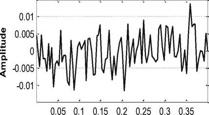
The most important factor in detecting damage in structures such as crack is noise discussion. When in practical mode shapes signals are recorded as Operating deflection shape (ODS), it contains noises. In order to show the performance of our proposed method in noisy conditions, we show it with a simulation. At this stage, we create a crack at a depth of 20% of the height of the beam, i.e. a crack with a depth of 2 mm in the beam. The crack distance from the stand is x d =0.201m and the crack width is also 0.002m. To illustrate the effect of noise, we add noise to simulated forms of mode shapes to simulate the behavior of the real environment. To this end, we add random noise to modal signals. Fig.11 shows a sample of noise that is added to clean signals. The noise in this figure for ideal modal signals (i.e. clean and no noise) creates a signal-to-noise ratio (SNR) of 20dB. The SNR ratio is, according to the definition, SNR = 20 × log (S / N) where S is the signal energy and N is the noise energy. We used the most comprehensive noise, the white noise of the Gaussian.
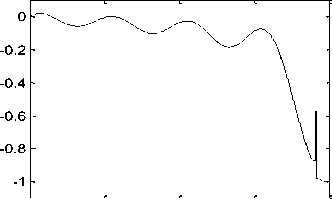
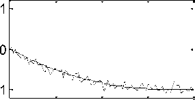
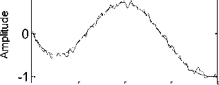
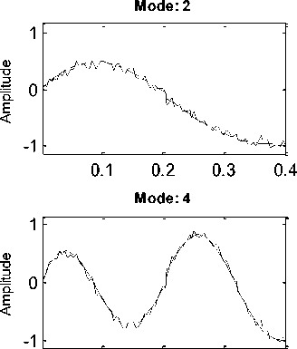
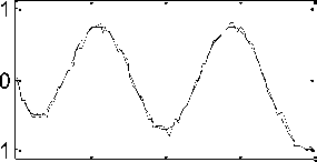
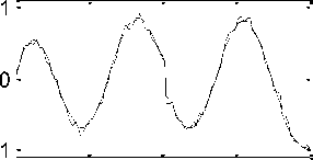
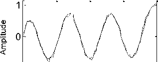
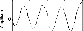
The first to eighth waveform curves after adding noise with SNR = 20dB were obtained as shown in Fig.12. It is noticeable that noise effectively damaged the mode shapes. In Fig.13, see the results of implementing our proposed method by implementing DWT on the sum of mode shapes. It is observed that the crack (at x d =0.201m from the support) is well detected with a noise signal with SNR = 20dB.
Mode: 1
Mode: 3
0.1 0.2 0.3 0.4
0.1 0.2 0.3 0.4
Mode: 5
0.1 0.2 0.3 0.4
Mode: 6
0.1 0.2 0.3 0.4
Mode: 7
-1
Mode: 8
-1
0.1 0.2 0.3 0.4
Beam Length (m)
0.1 0.2 0.3 0.4
Beam Length (m)
Fig.12. First to eighth mode shapes after adding noise with SNR = 20dB
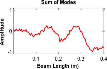
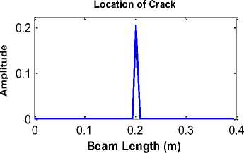
Fig.13. Results from the proposed DWT method, after adding noise with SNR = 20dB
-
VIII. Conclusion
In this research, wavelet analysis was performed based on the mode shapes of higher orders of the structure. First, we examined what kind of wavelet function and method for tracking cracks in the cantilever beam are optimal and provides more suitable results. Then, with the simulation of the basic conventional method that performed the wavelet analysis on the all mode shapes on the cantilever beam, we proposed a solution to improve it.
Finally, using our proposed technique, we evaluated it in different types of cracks in the cantilever beam. In the first result of this study, we distinguish the DWT method more suitable than CWT method by performing some experimental simulations.
According to literature, conventional method using high order mode shapes, it need to use a wavelet function for each Mode shape. Moreover, since mode shapes are influenced by the position, intensity and depth of the cracks, naturally, the pre-determined wavelet function do not act properly by new cracks with different characteristics (e.g. location and depth). So, to find the proper functions, we went through simulation of various types of functions known in the DWT space, and it has been found the db3 best function of the Daubechies family. The fact that the db3 function produces more appropriate results suggests that wavelet analysis is able to extract the singular points of the given signal (the mode shape of the cracked beam), and the more distinct points are more similar to the wavelet function. So, as the second result, the db3 function as the best wavelet function for this problem has been found.
By implementing the proposed method on a number of simulations, it shown that the proposed method is able to crack cracks with a variety of distances from the support, multiple cracks on the structure, Cracks with length of 20%, 10%, 5%, and 2% of the beam depth with a careful look.
The most important and prominent feature of this technique is in the discussion of the conditions of the noise signal, which is vital in realizing the practicality of any method. It shown that the proposed method is capable of detecting cracks in beams with recorded noisy signals.
-
[1] Dimarogonas A.D., Vibration Engineering, West Publishes, St. Paul, MN, 1976.
-
[2] Gudmaunson P., Engine frequency changes of Structures Due to cracks, notches or other geometrical changes. Journal of Mechanics and Physics of Solids vol. 30, pp. 339-353, 1982.
-
[3] Rizos P., Aspragathos N., Dimaroginas A.D., Identification of crack location and magnitude in Cantilever beam from the vibration modes. Journal of Sound and Vibration vol. 138, pp. 381-388, 1990.
-
[4] Farrar,C.R and D.V Jauregui,”Damage Detection Algorithms Applied experimental and numerical modal data from I-٤٠ bridge”, Los Alamos national laboratory report LA-13704-MS, 1996.
-
[5] West, W.M,”Illustration of the use of modal assurance criterion to detect structural changes in an orbiter test specimen: in proc. Air force conference on aircraft structural integrity,pp. 1-6,1984.
-
[6] Fox,C.H.J.,”The location of defect in structures :A
comparison of the use of natural frequency and mode shape data”, in proc. Of the 10th international modal analysis conference, pp. 522-528, 1992.
-
[7] Ratcliffe, C.P,” Damage detection using a modified
Laplacian operator on mode shape data”. Journal of Sound and Vibration, vol. 204, pp. 505-507, 1997.
-
[8] Banks H.T., Inman D.J., Leo D.J., Wang,Y.; “An experimentally validated damage detection theory in smart structures”, Journal of Sound and Vibration vol. 19, pp. 859-880, 1996.
-
[9] S. Loutridis, E. Douka, A. Trochidis, " Crack identification in double-cracked beams using wavelet analysis" Journal of Sound and Vibration, pp. 1025–1039, 2004.
-
[10] Sherif Beskhyroun,Toshiyuki Oshima and Shuichi Mikami, "Wavelet-based technique for structural damage detection" Published online in Wiley InterScience , 2013.
-
[11] Jeon Y., Choi D., Lee S., Yun P., "Defect detection for corner cracks in steel billets using a wavelet
reconstruction method", Journal of the Optical Society of America, vol.31(2), pp. 227-237, 2014.
-
[12] Yong-Ying Jiang, Bing Li, Zhou-Suo Zhang, Xue-Feng Chen, "Identification of Crack Location in Beam Structures Using Wavelet Transform and Fractal Dimension", Journal of Shock and Vibration, 2015.
-
[13] M. Abdulkareem, N. Bakhary, M. Vafaei, N. M. Noor, "Wavelet-based Damage Detection Technique via Operational Deflection Shape Decomposition", Indian Journal of Science and Technology, Vol 9(48), 2016.
-
[14] Okafor A.C., Dutta A., Structural damage detection in beams by wavelet transforms, Smart Materials and Structures, 9, 906-917, 2000.
-
[15] Gentile A., Messina A., "On the continuous wavelet transforms applied to discrete vibrational data for detecting open cracks in damaged beams", International Journal of Solids and Structures, 40, 295-315, 2003.
-
[16] Castro E., Garcia-Hernandez M.T., Gallego A., Defect identification in rods subject to forced vibrations using the spatial wavelet transform, Applied Acoustics, vol. 68, pp. 699-715, 2007.
-
[17] Rucka M., "Damage Detection in Beams Using Wavelet Transform on Higher Vibration Modes", Journal of Theoretical and Applied Mechanics, Vol. 49 (2), pp. 399417, 2011.
-
[18] Naresh Jaiswal, Deepak Pande, "Wavelet Transform of Modal Data of Beam in Damage Detection Exercise", Indian Journal of Science and Technology, Vol 9(26), 2016.
-
[19] Mallat, S." A Wavelet Tour of Signal Processing", Academic Press, San Diego, CA. 1998.
-
[20] MathWorks, Inc., Matlab, www.mathworks.com , ver. 2014.
-
[21] Daubechies I., Ten Lectures of Wavelets, Publisher: Society For Industrial & Applied Mathematics U.S., ISBN: 9780898712742, June 1992.
-
[22] T. M. Thasleema, N. K. Narayanan, "Multi Resolution Analysis for Consonant Classification in Noisy Environments", I.J. Image, Graphics and Signal Processing (IJIGSP), vol.4, no.8, pp. 15-23, 2012.
-
[23] S. Sridhar, P. Rajesh Kumar, K.V.Ramanaiah, "Wavelet Transform Techniques for Image Compression – An Evaluation", I.J. Image, Graphics and Signal Processing (IJIGSP), vol.6, no.2, pp. 54-67, 2014.
-
[24] Vandana Roy, Shailja Shukla, "Automatic Removal of Artifacts from EEG Signal based on Spatially Constrained ICA using Daubechies Wavelet", I.J. Image, Graphics and Signal Processing (IJIGSP), vol.6, no.7, pp. 31-39, 2014.
-
[25] ABAQUS/CAE, www.3ds.com , ver. 2016.
References A novel method for crack detection in steel cantilever beam using wavelet analysis by combination mode shapes
- Dimarogonas A.D., Vibration Engineering, West Publishes, St. Paul, MN, 1976.
- Gudmaunson P., Engine frequency changes of Structures Due to cracks, notches or other geometrical changes. Journal of Mechanics and Physics of Solids vol. 30, pp. 339-353, 1982.
- Rizos P., Aspragathos N., Dimaroginas A.D., Identification of crack location and magnitude in Cantilever beam from the vibration modes. Journal of Sound and Vibration vol. 138, pp. 381-388, 1990.
- Farrar,C.R and D.V Jauregui,”Damage Detection Algorithms Applied experimental and numerical modal data from I-٤٠ bridge”, Los Alamos national laboratory report LA-13704-MS, 1996.
- West, W.M,”Illustration of the use of modal assurance criterion to detect structural changes in an orbiter test specimen: in proc. Air force conference on aircraft structural integrity,pp. 1-6,1984.
- Fox,C.H.J.,”The location of defect in structures :A comparison of the use of natural frequency and mode shape data”, in proc. Of the 10th international modal analysis conference, pp. 522-528, 1992.
- Ratcliffe, C.P,” Damage detection using a modified Laplacian operator on mode shape data”. Journal of Sound and Vibration, vol. 204, pp. 505-507, 1997.
- Banks H.T., Inman D.J., Leo D.J., Wang,Y.; “An experimentally validated damage detection theory in smart structures”, Journal of Sound and Vibration vol. 19, pp. 859-880, 1996.
- S. Loutridis, E. Douka, A. Trochidis, " Crack identification in double-cracked beams using wavelet analysis" Journal of Sound and Vibration, pp. 1025–1039, 2004.
- Sherif Beskhyroun,Toshiyuki Oshima and Shuichi Mikami, "Wavelet-based technique for structural damage detection" Published online in Wiley InterScience , 2013.
- Jeon Y., Choi D., Lee S., Yun P., "Defect detection for corner cracks in steel billets using a wavelet reconstruction method", Journal of the Optical Society of America, vol.31(2), pp. 227-237, 2014.
- Yong-Ying Jiang, Bing Li, Zhou-Suo Zhang, Xue-Feng Chen, "Identification of Crack Location in Beam Structures Using Wavelet Transform and Fractal Dimension", Journal of Shock and Vibration, 2015.
- M. Abdulkareem, N. Bakhary, M. Vafaei, N. M. Noor, "Wavelet-based Damage Detection Technique via Operational Deflection Shape Decomposition", Indian Journal of Science and Technology, Vol 9(48), 2016.
- Okafor A.C., Dutta A., Structural damage detection in beams by wavelet transforms, Smart Materials and Structures, 9, 906-917, 2000.
- Gentile A., Messina A., "On the continuous wavelet transforms applied to discrete vibrational data for detecting open cracks in damaged beams", International Journal of Solids and Structures, 40, 295-315, 2003.
- Castro E., Garcia-Hernandez M.T., Gallego A., Defect identification in rods subject to forced vibrations using the spatial wavelet transform, Applied Acoustics, vol. 68, pp. 699-715, 2007.
- Rucka M., "Damage Detection in Beams Using Wavelet Transform on Higher Vibration Modes", Journal of Theoretical and Applied Mechanics, Vol. 49 (2), pp. 399-417, 2011.
- Naresh Jaiswal, Deepak Pande, "Wavelet Transform of Modal Data of Beam in Damage Detection Exercise", Indian Journal of Science and Technology, Vol 9(26), 2016.
- Mallat, S." A Wavelet Tour of Signal Processing", Academic Press, San Diego, CA. 1998.
- MathWorks, Inc., Matlab, www.mathworks.com, ver. 2014.
- Daubechies I., Ten Lectures of Wavelets, Publisher: Society For Industrial & Applied Mathematics U.S., ISBN: 9780898712742, June 1992.
- T. M. Thasleema, N. K. Narayanan, "Multi Resolution Analysis for Consonant Classification in Noisy Environments", I.J. Image, Graphics and Signal Processing (IJIGSP), vol.4, no.8, pp. 15-23, 2012.
- S. Sridhar, P. Rajesh Kumar, K.V.Ramanaiah, "Wavelet Transform Techniques for Image Compression – An Evaluation", I.J. Image, Graphics and Signal Processing (IJIGSP), vol.6, no.2, pp. 54-67, 2014.
- Vandana Roy, Shailja Shukla, "Automatic Removal of Artifacts from EEG Signal based on Spatially Constrained ICA using Daubechies Wavelet", I.J. Image, Graphics and Signal Processing (IJIGSP), vol.6, no.7, pp. 31-39, 2014.
- ABAQUS/CAE, www.3ds.com, ver. 2016.
