A Novel Object Position Coding for Multi-Object Tracking using Sparse Representation
Author: Mohamed ELBAHRI, Kidiyo KPALMA, Nasreddine TALEB, Miloud CHIKR EL-MEZOUAR
Journal: International Journal of Image, Graphics and Signal Processing(IJIGSP) @ijigsp
Article in issue: 8 vol.7, 2015.
Free access
Multi-object tracking is a challenging task, especially when the persistence of the identity of objects is required. In this paper, we propose an approach based on the detection and the recognition. To detect the moving objects, a background subtraction is employed. To solve the recognition problem, a classification system based on sparse representation is used. With an online dictionary learning, each detected object is classified according to the obtained sparse solution. Each column of the used dictionary contains a descriptor representing an object. Our main contribution is the representation of the moving object with a descriptor derived from a novel representation of its 2-D position and a histogram-based feature, improved by using the silhouette of this object. Experimental results show that the approach proposed for describing moving objects, combined with the classification system based on sparse representation provides a robust multi-object tracker in videos involving occlusions and illumination changes.
Multi-object tracking, Object representation, Orthogonal matching pursuit, Sparse representation, Classification
Short address: https://sciup.org/15013894
IDR: 15013894
Text of the scientific article A Novel Object Position Coding for Multi-Object Tracking using Sparse Representation
Published Online July 2015 in MECS DOI: 10.5815/ijigsp.2015.08.01
Video surveillance systems are widely used in public places. To make it more effective, the technical parts of computer vision emerging as a tracking of moving objects permit now to recognize, index, and track the path of everything moving in a video. In tracking systems, the challenge is to ensure the persistence of the object's identity by addressing the issues perturbing tracking algorithm such as target position changes, occlusion and illumination changes.
In the present study, tracking is formulated as a classification system. An online dictionary composed of sub-classes is used: each element of a sub-class representing the same object. Each column of the dictionary contains a descriptor of a detected object in previous frames. Initially, the dictionary is empty; it is then updated during the detection of any moving object.
A new sub-class is created in the dictionary to label any object appearing for the first time, and the system classifies the object into the same sub-class when it reappears again in the next frames. Sparse representation (SR) is used in different areas of computer vision and image processing [1,2,3,4,5,6]. The main goal of using sparsity is to represent [7] or classify an input signal by choosing a subset of models or features from data acquired during learning rather than the data itself [8,9]. In our work, we use sparse representation to classify the input test object. Object recognition can be expressed as a classification system through a linear regression model. This problem of SR-based classification can be addressed by computing the ℓ1 minimization [8,10,11,12]. In the present study, Orthogonal Matching Pursuit (OMP) is used to classify objects according to the sparse solution. This algorithm, proposed by Y. Pati [13], is an extension of the matching pursuit algorithm developed by Mallat et Zhang [14]. This algorithm aims at determining the sparse coefficients. The first step of OMP, is to select the column of the dictionary which generates the largest inner product with the current feature vector. Hence, the largest inner product generated by this vector with the ith column of the dictionary means that this column represents the same object in one of the previous frames.
The contribution of this work consists of the representation of objects. To get the largest product between two vectors representing respectively, two objects having similar colors and sharing the same location, we propose to represent moving objects, with two major parts. The first part represents the appearance of the object and the second its position. In our experiments, we focus on the people tracking video. Hence the object body is divided into two parts: the upper part and the lower one [15]. The motivation is that in everyday's life, people wear upper part clothes of colors different than those of lower part clothes. Moreover, instead of using bounding boxes like in the existing approaches, this description is then improved by using masks derived from the silhouette of the object to get the appearance feature, and by using a vector to represent the object position.
In the rest of this paper, we discuss the following issues: Section II presents some related work. In section III, we detail the proposed scheme to build the object descriptor. In section IV we give a brief introduction to sparse representation and summarize the OMP algorithm. Section V presents and discusses the experimental results while section VI concludes the paper.
-
II. Related work
In the literature, several approaches have been developed for object tracking [16,17,18,19]. In these methods, some authors locate the target object using information from the future frames and process for detection over large temporal windows. Black et al. [20] based their work on the optical flow to represent target objects. Jepson et al. [21] used a Gaussian mixture model of pixels to represent objects via an online expectation maximization (EM) algorithm. David et al. [21], implemented tracking with a particle filter instead of blobs of pixels. Avidan [23] trains a discriminative model using a Support Vector Machine (SVM) to detect moving objects and separate them from the background. In [24], some methods are proposed using classifiers to distinguish the moving objects.
Most recent research works have focused on sparse representation to deal with the problem of object tracking [25,26,27,28,29]. Lu et al. [15] present some experimentation of OMP and LARS [30] for tracking. Furthermore, the authors in [31] propose a kernel-based method with multikernel fusion into SR for robust visual tracking within the particle filter framework.
The proposed approach consists of two major steps: detection and recognition of moving objects. In this context, the adopted strategy is to describe moving objects by their appearance features and by their positions in the scene. For more accuracy, all of the information belonging to the background is removed. So after segmentation, the color histogram is computed and used as the first part of the descriptor. In section III-B, experimental results are given to illustrate how much background information can disturb the appearance description. To solve this problem, the proposed solution computes the histograms from a mask derived from the silhouette of the object.
The object descriptor, containing the appearance feature only, cannot assure the persistence of the objects identity. Integrating the object position in the descriptor will indeed contribute to improve the recognition. In several works [15,32,33], the position is encoded using the simple coordinates of the object for its representation; others use position to compute the distance between objects and the camera. In the present work, the position is encoded as a vector derived from the whole frame; this vector is concatenated with the vector representing the appearance feature.
-
III. Object detection and representation
Within the object-tracking framework, the detection and representation of the moving object are crucial steps. The objectives of these steps consists of detecting as accurately as possible moving object, and to represent it, with a model robust to illumination changes and to the occlusion problem.
-
A. Object Detection
In the case of a fixed camera, using background subtraction [34] is an effective way for motion detection. The result of this operation may however contain some undesirable noise due to background changes as illumination changes and undesirable movements that must be filtered. Other approaches are proposed in the literature such as "Mixture of Gaussian" to separate the foreground from the background [35], or some classification systems using features such as in Hog [36] and in Haar [37,38].
Fig.1 illustrates a background subtraction by computing the absolute difference between the background (Fig.1.a) and another frame acquired at a particular time (Fig. .b). After thresholding the result of the background subtraction, the bodies shapes are visible in Fig.1.(c).
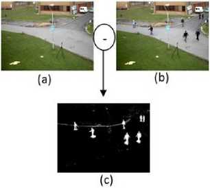
Fig. 1. (a) Background reference. (b) Observed scene. (c) Thresholded result of the background subtraction.
It is to note that in Fig. 1.c, the result of the subtraction does not include just the bodies’ shapes but some noise also. To improve the extraction of the detected moving objects bodies, mathematical morphology operations are used [39,40]. Erosion is applied to eliminate noise such as the one characterized by the white line due to the movement of the horizontal ribbon. This process uses a structuring element that consists of a (7x7) matrix of 0's and 1's values. The proposed structuring element eliminates the scattering pixels or those constituting horizontal shapes. However, erosion generates an adverse effect and dissociates bodies’ limbs as can be seen in Fig. 2 .(b), so we apply a dilation with another structuring element consisting of a (9x9) matrix to reconstruct the bodies shapes.
It was observed that the background subtraction technique is not very robust for the detection of the bodies shapes, when the scene is very crowded and the objects overlap. An approach has been proposed in the section III. D which aims to deal with the overlapping objects.
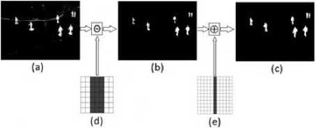
Fig. 2. (a) Background subtraction result. (b) Erosion result. (c) Dilation result. (d) Structuring element used for erosion. (e) Structuring element used for dilation.
-
B. Object Description
After the detection of the object's shape, edge detection is applied to the binary image resulting from the background subtraction to delineate the silhouette of the body of the moving object. In the proposed approach, the histogram is derived from this silhouette, while the majority of techniques used in this field calculate the histogram from bounding box of the object. So the proposed histogram is more accurate and more representative of the object. Fig. 3 represents the obtained edge detection.
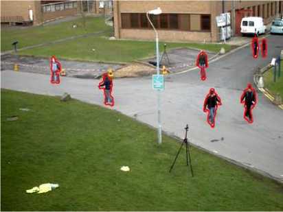
Fig. 3. Detected edges superposed on the original image.
For each detected object, a rectangular mask is extracted from the binary image (Fig.2.c) . Fig. 4 shows a zoom of a detected object (Fig.4.a) as well as the mask extracted for the same object (Fig.4.b). A 0 value represents the background (black), while a 1 value represents pixels of the object body silhouette (white).
Using silhouettes as masks of the objects makes histograms more accurate since only pixels representing the moving objects are accounted. In the following example (Fig.5), the histograms are computed from two bounding boxes representing the same person in different frames. From each bounding box, the histogram is computed in two ways: the first using the mask and the second without it.
After that, the similarity is measured between each pair of histograms. Figures 5.a and 5.c show the same person Black pixels represent 42% of the entire box, hence, the background pixels distort the curve of the graph representing the histogram.in different frames and in locations with different backgrounds. Fig.5.b shows only a person without the background pixels.
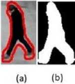
Fig. 4. (a) Contour of the object (b) Corresponding mask of the object.
It is noted that in the graph corresponding to Fig.5.a, the peak at level L a represents the background pixels and it is higher than the one at level Lb of the graph corresponding to the Fig.5.b. The peak at level La is reduced when the histogram is computed using the mask. The goal of this approach is to improve the similarity between two histograms representing the same person and subsequently reducing the effect of the background. As can be seen, for example, the green graphs in figures 5.b and 5.d are more similar than those of figures 5.a and 5.c. This is confirmed by the similarity measured in both situations.
The degree of similarity between two images can be measured with the correlation between their histograms. Let ℎ-£ arid ℎ2 be the histograms of two images ^1 and /2 , respectively. The correlation between these histograms is defined as:
dc (ℎi,ℎ2)=
∑ ( t ) ^2 ( t )
√∑ £1 hi ( t ) ∑ £1 h2 ( t )
where C ∈ { R , G , В } with 0≤ d-c (ℎ ,ℎc2)≤1 , and if d-c (ℎ ,ℎ2)≈1 then ℎ and ℎ 2 are similar.
Let ℎ ,ℎ ̂ ,ℎ 2 ,ℎ ̂2 , be the histograms corresponding to Fig.5.a, Fig.5.b, Fig.5.c and Fig.5.d, respectively. The average correlation between the histograms of the three color channels of the example in Fig.5 is as follows: ̅̅̅̅ ( ̅ ℎ ̅̅̅ , ̅ ℎ ̅̅̅ ) ̅ = 0 ,53 avid ̅̅̅̅ ( ̅ ℎ ̂̅̅̅ , ̅ ℎ ̅̂̅̅ ) ̅ = 0,83. It is to notice that ̅̅̅̅ ( ̅ ℎ ̂̅̅̅ , ̅ ℎ ̅̂̅̅ ) ̅ > ̅̅̅̅ ( ̅ ℎ ̅̅̅ , ̅ ℎ ̅̅̅̅ ).
The correlation of histograms representing the same person in different scenes with different backgrounds using silhouette masks is greater than that using a bounding box. Based on this observation, we confirm that using the silhouette as a mask in the histogram construction is highly beneficial.
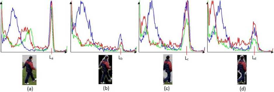
Fig. 5. Example of Color histograms of the images.
C. Position Feature
The position of the moving objects contributes to the objects recognition. It is represented in literature with the coordinates of the center of the object. The classification algorithm used in this work for recognition is based on the inner product for the selection of the most correlated column in the dictionary with the input test object. However, the inner product of simple coordinates cannot provide information about the distance between two objects: two objects can be highly correlated but far from each other and close objects can be weakly correlated.
To illustrate this statement, let Р[ s be the positions of three objects at tl, and ̂ s be the positions of the same three objects at ^2 , respectively, where Р[ , ̂ ∈ ℝ2×1 and i , j ∈ {1,2,3}. Following the example in Fig.6, we obtain the following equation:
("person1" and another that we call "person2") are illustrated by figures 7.b.2 and 7.c.2, respectively. It is noted that in each position matrix, the red cell corresponds to the object center. For the other cells, their color is modified according to the distance between them and the red one.
To implement the used approach, matrix Q ∈ ℝ , initially contains only zeros. We set the value a ∈ ℝ + to
cell , corresponding to the coordinates ( x ,у) of the
object center where =
⌊ I ⌋ ,1= ⌊ ? ⌋
, with i , j ∈ ℕ, ℎ is
∀ I , argmaxj 〈 Pi , ̂ 〉 =3 (2)
where 〈 Pi , ̂ 〉 =./×
/ . After observing the results
of the inner product of the different positions in Table1,
we confirm formula (2), and the largest inner product is the one generated with the position ̂3 corresponding to the farthest object from the origin.
However, we need to represent the position such that:
∀ i , argmaxj 〈 Pt , ̀ 〉 = i
To satisfy the formula (3), a novel representation of the position is proposed in this work. The idea is to create a structure to encode the position of each detected object. This structure is derived from a matrix Q ∈ ℝ , created for each detected object. This matrix, called the position matrix, is used to sample the image in small areas.
Fig.7 shows the position matrices of three detected objects. The frame in Fig.7.a.1 is acquired at ti and the position matrix in Fig.7.a.2 is used to represent the position of the person that we call "person1". figures 7.b.1 and 7.c.1 show the frame acquired at ^2 , and the position matrices corresponding to two persons
the image height and w its width. The other cells values are:
0 • ={ a - Y^if ≥0 (4)
, ={ 0 (4)
where
Y
= max(|
I'
-
i
|,|
j’
-
j
|)
and S
∈
ℝ:0
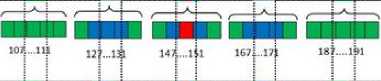
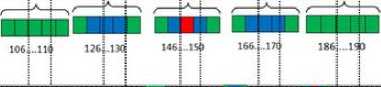
The position matrix must be modified in order to be concatenated with the vector encoding the histogram representing the appearance feature. A position vector is created by applying a zig-zag scan on the position matrix. Figures 8.a, 8.b and 8.c show the position vectors corresponding to the position matrices of figures 7.a.2, 7.b.2 and 7.c.2, respectively.
Table 1: Result of the inner products of the objects' positions according to Fig. 6
|
〈 Pi , ̂ 〉 |
j=1: (30,15) |
j=2: (60,30) |
j=3: (90,50) |
|
i=1: (20,15) |
825 |
1650 |
2250 |
|
i=2: (60,25) |
2175 |
4350 |
6650 |
|
i=3:(100,45) |
3675 |
7350 |
11250 |
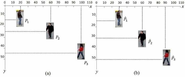
Fig. 6. (a) Objects positions at t1 . (b) Objects positions at t2 ..
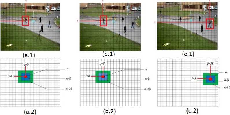
Fig. 7. Different Q position matrices. The red colored cell corresponding to the center of the object contains value a. (a.2), (b.2) and (c.2) show the position matrices of the detected objects.
llllllllllllllllllllllllllllllll lllllllllll lllllllllll lllllllllll llllllllllll lllllllllllllllllllllllllllllllllllllllllllllllllllllllll
lllllllllllllllllllllllllllllll llllllllll lllllllllll lllllllllll lllllllllll llllllllllllllllllllllllllllllllllllllllllllllllllllllllll
liiiiiiiiiiiiiiiiiiiiiiiiiiHiiHiiiiiiiiiiiiiiiiiiiiiiii iiiiiiiiiii iiiiiiiiiii iiiiniiiiiiT iiiiiiiiini iiiiiiiiiiiiiiiiiiiiiiiiiini
(a)
(b)
(c)

136....140 156...160 176....180 196....200 216....22O
Fig. 8. Position vectors. (a), (b) and (c) represent the linearization of the position matrices corresponding to figures 7. (a.2), 7. (b.2) and 7. (c.2), respectively.
We call Vpos it ion. E Kmxn the vector obtained after a zig-zag scan of the Q position matrix. Let Et = {1,..., PJ an d Et+1 = {1,..., Pt +3 be the set of indices of the objects detected at t and t+1 , andVpo s it io n1 the position vector of object . If (Vp osi tion\ Vp os it ionu) » 0 , Where 1 E Et nnd u E
, then the two objects are located in positions close to each other. If(Vposition1, Vpositionu) = 0, then the distance between the positions of both objects is large.
For example, we suppose that
, , are the position vectors shown in figures 8.a, 8.b and 8.c, respectively.
Since the location of the colored areas of vector matches that of vector and does not match that of vector Vposition3 , the inner product 〈Vposition1, Vposition2〉≫〈Vposition1, Vposition3〉.
-
D. Overlapping Objects
As mentioned above, overlapping represents a tough problem in the detection process, especially when the background subtraction is used as the detection technique. The overlapped objects may be considered as one; this case is detected when the width of the bounding box containing the object exceeds 55% of its height. In the case where overlapping is lateral, we use the mask to divide the box into two boxes, each one containing the shape of one object. The distribution of white pixels in the upper part of the mask, permits to determine the number of overlapped objects (Fig.9). Threshold Δ is set in order to get the number of heads of people figured in the bounding box. Once the objects are correctly detected, the proposed tracker computes their appearance features again.
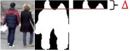
Fig. 9. Overlapped objects.
-
E. Object Descriptor
In this study, the proposed descriptor is defined as a concatenation of two major vectors: the appearance feature and the position feature. As introduced previously, the RGB histogram is built after dividing the body into two parts, the upper part and lower one from the center. Three vectors are obtained for each half, meaning six vectors to describe the entire body: { VRUP ∈ ℝ к ×1, VGup ∈ ℝ к ×1, VBup ∈ ℝ к ×1, VRiow ∈
ℝ к ×1, VGl0W ∈ ℝ к ×1, VBl0W ∈ ℝ к ×1 } where к represents the number of levels of each color channel. We denote by VH the concatenation of these six vectors. VH represents the vector encoding the appearance feature. The descriptor У of a detected object (see Fig.10), is a concatenation of seven vectors VRup , VGup , VBup , VRiow , VGl0W , VBl0W , and. Vposition . Descriptor У is normalized in order to be used in the classification system employed for object recognition presented in section (IV).
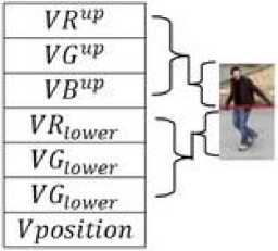
Fig.10. Object descriptor.
-
IV. Object Recognition Using Sparse Representation
Recognition can be formalized as a classification process through a linear regression model. This problem can be addressed by solving the ℓ1 minimization based on sparse representation [8]:
у= + E (5)
Solving the linear system (5) can be the key to addressing the recognition problem; where У ∈ ℝ м ×1 is the descriptor of the moving object and E is the tolerated error. This vector contains information representing the object description defined above. All descriptors of objects detected in the previous frames are collected in a dictionary A ∈ ℝ м × N . The coefficients of P ∈ ℝN are needed to determine the class of this object.
-
A. Sparse Representation-based Classification (SRC)
The main goal of this work is to discriminate detected objects and to index them with the same label wherever they are located in the scene, even when they leave the scene and return back after a few frames. The used classification system based on sparse representation, can be expressed as follows:
The dictionary A , contains N object descriptors collected from previous frames.We denote by no the number of labeled objects, for the ith one ,we regroup its П[ descriptors detected in the previous frames to create the object class Act =[ Vil , Vi2 , vt3 ,…, ^tllt ] ∈ ℝ M × "i , where V ∈ ℝ M ×1 , 0< i ≤ no and ∑ ™1 П[ = . By proceeding this way, the dictionary can be considered as the concatenation of no classes corresponding to no labeled objects:
A =[ Aci , AC2 , Асз ,…, ^c no ] . The descriptor У of the test object detected from current frame, can be approximated by the linear combination of known objects as in formula (5), where β =( β 1, β 2, β N) ∈ ℝN is the sparse vector. It is stated k-sparse if | supp ( p )|≤ к , where supp ( p )={ j : ≠0 }
Fig.11.a, shows an input signal У to be linearly approximated. Figures 11.b, 11.c, 11.d and 11.e, represent classes of labeled objects. These classes constitute dictionary A . They contain descriptors of objects detected at the previous frames. As can be seen in Fig.11.b, the class contains three vectors representing the same object at different detection steps.
The sparse solution can be solved as a linear regression problem, and can be formulated by the following stable ℓ1 -minimization problem derived from the sparse solution of formula (5) :
( ℓ 1): ̂= argmin {‖ У - AP ‖2+ T ‖ p ‖1 } (6)
where T is a cost parameter. To classify each new test object represented by У , we compute its sparse representation by minimizing the number of nonzero entries of sparse vector p and the residual.
̂ = ‖ ‖ subject to ‖ - ‖ ≤ (7)
Now, for associating the object represented by to the ith class in the training set, can be approximated by:
̂= (8)
where =[0,..,0, , ,.., ,0,..,0] is a vector obtained by setting to zero all entries not associated to the class. The linear representation of can be rewritten as:
̂ = + +⋯+(9)
Using this approximation, any detected object can be assigned to the ith class that satisfies:
()= ‖ - ̂)‖ = ‖ - )‖(10)
where 0< ≤.
When non-zero coefficients are scattered over all classes, and:
max(∑ )< ∑ where 0< <1 is a threshold constant, then the object is considered as a new class.
(a) (b) (c) (d) (e)
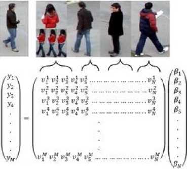
Fig. 11. Graphic representation of the linear system y=Αβ. (a): Detected object test. (b), (c) , (d) and (e) represent classes of labeled objects.
Fig.12 represents an example of the adopted solution. The dictionary employed for the recognition contains 30 labeled training objects corresponding to 6 classes (Fig.12.a). After computing the sparse solution for two detected objects, the coefficients of the corresponding vectors are represented in figures 12.b and 12.c. The first object has already appeared and thus exists in the dictionary. Its sparse coefficients are grouped in the second class (see the second class of Fig.12.a). However, the object in Fig.12.c is new, so it does not exist in the dictionary: as a consequence, its sparse coefficients are scattered over many classes.
As explained before, the problem of recognition consists of finding the values of the sparse coefficients. To get these values, SRC can operate as an iterative greedy algorithm that selects at each step the column of which generates the largest inner product with the current residuals respecting formula (9). This is done by the OMP algorithm described below.
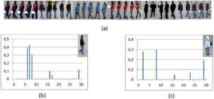
Fig. 12. Linear approximation of two objects, existing one and new one. (a) 30 labeled training objects corresponding to 6 classes. (b) Graph representing the sparse coefficients of a detected existing object. (c) Graph representing scattered coefficients of a new object.
-
B. OMP Algorithm
In SRC, several algorithms are proposed [30,41]. Our implementation consists of an OMP used to find the sparse coefficients. This algorithm was chosen for its speed of convergence due to the orthogonal projection [42,43]. In [15], Weizhi Lu et al. have shown that even when the dictionary has some false training samples, the sparse coefficients can be correctly grouped using the OMP algorithm.
The OMP algorithm can be presented as follows:
As inputs, we have a signal ∈ℝ × and a matrix ∈ℝ × containing columns. ( )is a submatrix of where ⊆{1,2,…, } represents a subset. We denote by the number of iterations and by the subset corresponding to the iteration. Once the residual or the number of iteration reaches some fixed threshold, then the vector ̂∈ℝ × contains the sparse solution, where is the last step.
Algorithm. 1 : Orthogonal Matching Pursuit algorithm
Input : and .
Output : ̂ .
Initialize : r0=y, A( c0 )={}.
t=1;t=t+1
Stage 1. Find the column that solves the maximization problem 〈 , where ∈{1,2,…, } \
Update =
Stage 2. Compute ̂=( ( ) ( )) ()
and = ( ) ̂, where denote the projection onto the linear space spanned by the elements of ()
Stage 3. Update =( -)
Stage 4. If ‖ ‖ < or reaches the maximum number of the authorized iterations, then stop the algorithm. .
-
C. Online Dictionary Updating
Once the object is classified, it will be stored temporarily until the end of the procedure for all objects. After that, it is added to the dictionary, more precisely in the appropriate class. All descriptors belonging to the same class will also be amended by updating the position part to become the same as the position part of the new descriptor added to their class.
-
V. Experiments And Results
The proposed algorithm is experimentally validated on a benchmark video and compared with other methods of the literature: MTUSR [15], ETHZ [44] and EPFL [45]. In our experiments the Q matrix is of size 20 x 20; it is set relatively to the size of the image and the moving objects. We computed the histogram and stored it without any quantification for more precision. So the size of each of the six histogram vectors is 256. The total size of our descriptor is therefore (256*6+20*20)=1936.
-
A. Dataset
We benchmarked our algorithm on PETS '09 dataset [46]. This video is filmed to be a reference in object tracking and it is used in many approaches. This video is not very crowded but the discrimination is a big challenge because the people wear clothes with similar colors. In 800 frames forming the video, 10 people must be initially indexed at their first appearance in the scene and must be recovered when they leave the scene and reappear again.
-
B. Results
All persons are correctly initialized and recognized [47]. They are indexed starting from 0 according to the order of their appearance in the video. The use of the position vector presented in section III-b, contributes when the colors are similar. In Fig.13.a the descriptor used for this example is built only with color histograms. When some objects are hidden (person number 2 on the left frame of Fig.13.a is hidden on the right frame), there is some confusion between this person and another who appears for the first time on the right frame of Fig.13.a. Fig.13.b is an example showing the efficiency of adding the position vector in our descriptor. Furthermore, the position vector makes the tracker robust in the case of the partial occlusion (see Fig.14). In Fig.15 the proposed method dealt successfully with overlapping and allowed detecting as much as possible moving objects. In frame_0160 of Fig.15, two objects are not detected by MTUSR because of overlapping, but they are well detected by ETHZ, EPFL and the proposed method. In frame_0031 of the same figure, two persons are considered as one by MTUSR, but are well separated by ETHZ, EPFL and our method. The reason is that, in the MTUSR approach, when the bounding box size containing the moving object is excessively large, the algorithm simply avoids this case of detection or considers two objects as one if they overlap a little; while we solved this kind of problem as explained in section
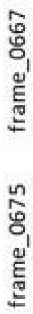
III-d. The similarity of the clothes colors causes a confusion between intersecting objects. Some methods are not very robust to handle these situations. As can be seen in Fig.16, the overlapping reverses the indices of objects 6 and 8 between frame_0667 and frame_0675 using the EPFL method based on the trajectories of the moving objects; it is mentioned in [45] that EPFL is not applicable when the object's movements are way too erratic. The ETHZ, MTUHZ methods and the proposed approach based on the online trained dictionary, seem robust in these cases.
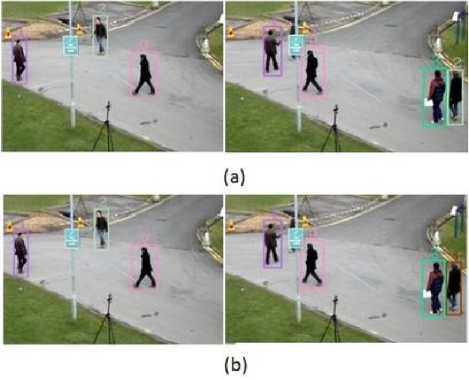
Fig. 13. Recognition using our algorithm.(a) New person is indexed as an existing person. (b) Correct initialization of new objects.
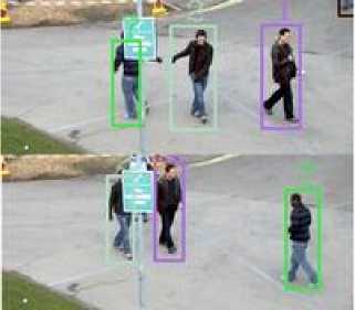
Fig. 14. Example of the partial occlusion.
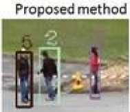
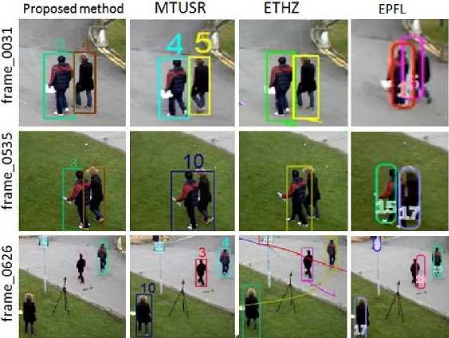
When the objects leave the scene and reappear again in the future frames, the system must recover them. In Fig.17 our method, maintains the index of the person number 5 in frame_0063 and frame_0471. The MTUSR approach works well too. Both MTUHZ and our method use the appearance features and the position feature; but for ETHZ using a particle filtering framework and for the EPFL methods, we can see that the recovery process is false, and the same person is differently colored in the frames. In Fig.18, the persons indexed as 3 and 4 in frame_0031 are well recovered in frame_0535 and frame_0626 by the proposed method. MTUSR does not recover the persons indexed as 4 and 5 in frame_0535 and they are considered as a new person indexed as 10. In frame_0626, only the person indexed as 4 is recovered by MTUSR. ETHZ does not detect the person in frame_0535 and switches the identity of two persons in frame_0626. EPFL does not recover the persons correctly between frames_0031 and the other frames. The reason making our method more effective is the way to represent the objects as described in section III-b.
Table 2 summarizes the number of the persons entries and reappearance in the scene. The proposed approach seems robust for a good recognition. According to Table 2, MTUSR, ETHZ and EPFL have respectively 2, 6 and 7 errors of initialization and recovery.

Fig. 15. Visual comparison of the overlapping treatment with four approaches.
MTUSR ETHZ EPFL
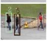
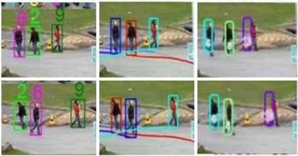
Fig. 16. Illustration of the problem of identity switch caused by overlapping: visual comparison of our method with MTUSR, ETHZ and EPFL.
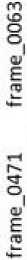
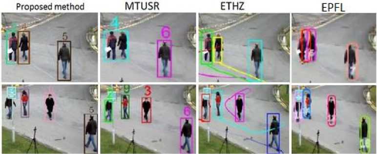
Fig. 17. Illustration of the recovery process with a visual comparison of the proposed method with the MTUSR, ETHZ and EPFL recovery processes.
Proposed method MTUSR ETHZ
EPFL
Fig. 18. Illustration of the problem of the false initialization and the recovery process with a visual comparison of the proposed method with MTUSR, ETHZ and EPFL.
Table 2. Objects entries and reappearance in the scene, the F value means false object initialization. The last column contains the number of errors of each method
|
Objects |
0 |
1 |
2 |
3 |
4 |
5 |
6 |
7 |
8 |
9 |
N |
|
Number of entries |
2 |
4 |
2 |
2 |
2 |
2 |
1 |
1 |
2 |
1 |
E |
|
Proposed approach |
2 |
4 |
2 |
2 |
2 |
2 |
1 |
1 |
2 |
1 |
0 |
|
MTUSR |
2 |
4 |
2 |
1 |
1 |
2 |
1 |
1 |
2 |
1 |
2 |
|
ETHZ |
2 |
4 |
2 |
1 |
1 |
1 |
1 |
1 |
F |
F |
6 |
|
EPFL |
1 |
2 |
1 |
1 |
1 |
1 |
1 |
1 |
2 |
1 |
7 |
-
VI. Conclusion
In this paper, a tracking algorithm based on sparse representation with an online dictionary learning is proposed. The proposed tracker uses only the color histogram and position as information to describe the moving object. To assure the persistent identity of the objects, we have proposed a new way to describe the object position and to improve its appearance feature. Experimental results obtained by applying this new technique to a complex benchmark video, demonstrate the efficiency of our approach compared to some existing methods. To get this precision, we have built large descriptors and thus the processing time has increased with the growth of the dictionary. We therefore suggest as a perspective work the use of some parallel implementation to reduce the computation time.
Acknowledgments
This work was supported in part by the Franco-Algerian cooperation program PHC TASSILI grants. Entitled “Système Conjoint de Compression et d’Indexation Basé-Objet pour la Vidéo (SCCIBOV),” the project gathers members of Institut National des Sciences Appliquées (INSA) de Rennes, Université de Technologie de Compiègne (UTC), the University of Sidi Bel Abbès and the University of Mascara.
References A Novel Object Position Coding for Multi-Object Tracking using Sparse Representation
- J. Starck, M. Elad, and D. Donoho, "Image decomposition via the combination of sparse representation and a variational approach," IEEE Trans. on Image Processing, vol. 14, no. 10,pp. 1570–1582, 2005.
- Y. Li, A. Cichocki, and S. Amari, "Analysis of sparse representation and blind source separation," Neural Computation, vol. 16, no. 6, pp. 1193–1234, 2004.
- B. Olshausen, P. Sallee, and M. Lewicki, "Learning sparse image codes using a wavelet pyramid architecture," in NIPS, 2001, pp. 887–893.
- M. Elad and M. Aharon, "Image denoising via learned dictionaries and sparse representation," in CVPR, 2006.
- M. Elad, B. Matalon, and M. Zibulevsky, "Image denoising with shrinkage and redundant representation," in CVPR, 2006.
- S. Zhao,Z.Hu " Modular Fisher Discriminant Sparse Representation for robust face recognition " Optik 125 (2014) 6505–6508
- E. Cande`s, "Compressive Sampling," Proc. Int'l Congress of Mathematicians, 2006.
- J. Wright, A. Y. Yang, A. Ganesh, S. S. Sastry, and Y. Ma, "Robust face recognition via sparse representation," IEEE Tran. PAMI, vol. 31, pp. 210–227, 2009.
- M. Yang and L. Zhang, "Gabor feature based sparse representation for face recognition with gabor occlusion dictionary," in ECCV, 2010.
- S. Chen, D. Donoho, and M. Saunders, "Atomic decomposition by basis pursuit," SIAM J. Scientific Computing , vol. 20, no. 1, pp. 33–61, 19
- I. Drori and D. Donoho, "Solution of L1 minimization problems by LARS/Homotopy methods," in ICASSP, 2006, vol. 3, pp. 636–639.
- Emmanuel J. Candès and Yaniv Plan. "Near-ideal model selection by ?1 minimization". Ann. Statist. Volume 37, Number 5A (2009), 2145-2177.
- Y. Pati, R. Rezaiifar, and P. Krishnaprasad, "Orthogonal matching pursuit: Recursive function approximation with applications to wavelet decomposition," in 27th Annual Asilomar Conference on Signals, Systems, and Computers, 1993.
- S. Mallat and Z. Zhang, "Matching pursuits with time-frequency dictionaries," IEEE Trans. on Signal Processing, vol. 41, pp. 3397–3415, 1993.
- W. Lu, C. Bai, K. Kpalma and J. Ronsin "Multi-object Tracking using Sparse Representation", ICASSP 2013, May 26-31, 2013, Vancouver, Canada (2013).
- M. Andriluka, S. Roth, and B. Schiele, "People-Tracking-by-Detection and People Detection-by-Tracking," Proc. IEEE Conf. Computer Vision and Pattern Recognition, 2008.
- J. Berclaz, F. Fleuret, and P. Fua, "Robust People Tracking with Global Trajectory Optimization," Proc. IEEE CS Conf. Computer Vision and Pattern Recognition, 2006.
- H. Fang, J. Kim and J. Jang "A Fast Snake Algorithm for Tracking Multiple Objects" Journal of Information Processing Systems, Vol.7, No.3, September 201
- B. Leibe, K. Schindler, N. Cornelis, and L.V. Gool, "Coupled Object Detection and Tracking from Static Cameras and Moving Vehicles," IEEE Trans. Pattern Analysis and Machine Intelligence, vol. 30, no. 10, pp. 1683-1698, Oct. 2008.
- M. J. Black. Eigentracking: Robust matching and tracking of articulated objects using a view based representation. In ECCV, pages 329–342, 1996.
- A. D. Jepson, D. J. Fleet, and T. F. El-Maraghi. Robust online appearance models for visual tracking. PAMI, 25(10):1296–1311, 2003.
- D. Ross, J. Lim, R.-S. Lin, and M.-H. Yang. Incremental learning for robust visual tracking. IJCV, 77(1-3):125–141, 2008.
- S. Avidan. Support vector tracking. In CVPR, pages 184–191, 2001.
- S. Avidan. Ensemble tracking. PAMI, 29(2):261–271, 2007.
- J. Shao et al. " Multi-part sparse representation in random crowded scenes tracking "Pattern Recognition Letters 34 (2013) 780–788
- M. Xue and L. Haibin, "Robust visual tracking using l1 minimization,"in Proc. Int. Conf. Comput. Vision, 2009, pp. 1436–1443.
- C. Bao, Y. Wu, H. Ling, and H. Ji, "Real time robust l1 tracker using accelerated proximal gradient approach," in Proc. IEEE Conf. Comput.Vision Pattern Recogn., Jun. 2012, pp. 1830–1837.
- Z. Han, J. Jiao, B. Zhang, Q. Ye, and J. Liu, "Visual object tracking via sampled-based adaptive sparse representation," Pattern Recogn., vol. 44, no. 9, pp. 2170–2183, Mar. 2011.
- Q. Wang, F. Chen, W. Xu, M. Yang : "Online discriminative object tracking with local sparse representation". WACV 2012: 425-432
- B. Efron, T. Hastie, and R. Tibshirani, "Least angle regression," Annals of Statistics, vol. 32, pp. 407–499,2004.
- L. Wang, H. Yan, K. Lv, and C. Pan "Visual Tracking Via Kernel Sparse Representation With Multikernel Fusion", IEEE TRANSACTIONS ON CIRCUITS AND SYSTEMS FOR VIDEO TECHNOLOGY, VOL. 24, NO. 7, JULY 2014.
- Y. Lin, Q. Yu, G. Medioni "Efficient detection and tracking of moving objectsin geo-coordinates" Machine Vision and Applications (2011) 22:505–520.
- W. Sai, L. Zhengyi, H. Chuanwen "An Implementation of Distance Measure for Dynamic Scene" 2013 Fourth International Conference on Intelligent Control and Information Processing (ICICIP) June 9 – 11, 2013, Beijing, China.
- A. Amato, M. Mozerov, F. X. Roca, and J. Gonzlez,"Robust real-time background subtraction based on local neighborhood patterns," EURASIP J. Adv. Sig. Proc., 2010.
- Yu, Guoshen . "Solving Inverse Problems with Piecewise Linear Estimators: From Gaussian Mixture Models to Structured Sparsity". IEEE Transactions on Image Processing 21 (5): 2481–2499.
- N. Dalal and B. Triggs. Histograms of oriented gradients for human detection. In Proc. CVPR, 2005.
- P. Viola and M. Jones, "Robust real-time face detection," presented at Second International Workshop on Statistical and Computational Theories of Vision - Modeling, Learning, Computing, and Sampling, Vancouver, Canada, pp. 1-25, 2001.
- P. Viola and M. Jones, "Rapid object detection using a boosted cascade of simple features," presented at 2001 IEEE Computer Society Conference on Computer Vision and Pattern Recognition, pp. I-511-I-518 vol.1, 2001
- A. Belgherbi.,A. Bessaid: " Morphological Segmentation of the Spleen From Abdominal CT Images " IJIGSP Vol.4, No.4, May 2012
- Liang JI, Jim Piper, "Erosion and dilation of binary images by arbitrary structuring elements using interval coding", Pattern Recognition Letters Volume 9, Issue 3, April 1989, Pages 201–209
- Q. Feng , "Novel classification rule of two-phase test sample sparse representation" Optik 125 (2014) 5825–5832
- T. Tony Cai and Lie Wang "Orthogonal Matching Pursuit for Sparse Signal Recovery With Noise" IEEE TRANSACTIONS ON INFORMATION THEORY, VOL. 57, NO. 7, JULY 2011
- J. Zhang , H. Zhang , Z. Li ,"A hierarchical structure with improved OMP sparse representation used with face recognition", Optik 125 (2014) 4729–4735
- M. D. Breitenstein, F. Reichlin, B. Leibe, E. KollerMeier, and L. V. Gool, "Online multi-person tracking-by-detection from a sing and uncalibrated camera," IEEE Trans. PAMI, vol. 33, no. 9, pp. 1820–1833, 2011.
- H. B. Shitrit, J. Berclaz, F. Fleuret, and P. Fua, "Tracking multiple people under global appearance constraints,"in ICCV, 2011.
- J. Ferryman, A.-L. Ellis "Performance evaluation of crowd image analysis using the PETS2009 dataset" Pattern Recognition Letters 44 (2014) 3–15
- "Online Multi-object tracking using Sparse representation " https://www.youtube.com/watch?v=8WX2Rvn36mQ
