A Novel Solution for Discriminating Wormhole Attacks in MANETs from Congested Traffic using RTT and Transitory Buffer

Author: Maria Sebastian, Arun Raj Kumar P.
Journal: International Journal of Computer Network and Information Security(IJCNIS) @ijcnis
Article in issue: 8 vol.5, 2013.
Free access
Nowadays, the computing and communication services are accessed while on the move. Setting up of fixed access points and backbone infrastructure is not always viable. So in order to provide communication where there is lack of infrastructure or inconvenience in using the existing infrastructure, Mobile Adhoc Networks (MANETs) are used. This inherent flexibility allows MANETs to be used for a wide range of applications such as rescue operations, military applications, vehicular communication, and business meetings. As there is no apriori trust relationship between the nodes of an ad hoc network and basic network functions like packet forwarding and routing are performed by the available nodes, security is an essential component in MANETs. Various attacks in MANETs are blackhole attack, byzantine attack, resource consumption attack, rushing attack, and wormhole attack. Wormhole attack is a severe threat among the other threats in MANET. Existing solutions to detect wormhole attacks include Packet Leashes, SECTOR, DelPHI, RTT-TC, TTM, etc. These solutions require special hardware or strict synchronized clocks or cause message overhead. Some solutions do not locate the wormhole, and some other may generate false alarms or does not consider network congestion into account. In this paper, wormhole attack detection is proposed based on RTT between successive nodes and congestion detection mechanism. If the RTT between two successive nodes is higher than the threshold value, a wormhole attack is suspected. If a wormhole is suspected, node's transitory buffer is probed to determine whether the long delay between the nodes is due to wormhole or not, as delays can be caused due to congestion or by queuing delays. The proposed method prevents both the hidden and the exposed attack. Advantage of our proposed solution is that it does not require any specialized hardware or synchronized clocks.
MANET, Wormhole attack, RTT, Transitory buffer
Short address: https://sciup.org/15011216
IDR: 15011216
Text of the scientific article A Novel Solution for Discriminating Wormhole Attacks in MANETs from Congested Traffic using RTT and Transitory Buffer
Published Online June 2013 in MECS
With the proliferation of cheaper, smaller, and more powerful mobile devices, mobile ad hoc networks
(MANETs) have become one of the fastest growing areas of research. This new type of self-organizing network combines wireless communication with a high degree of node mobility. Due to numerous constraints such as lack of infrastructure, dynamic topology and lack of preestablished trust relationships between nodes, most of the envisioned routing protocols for ad hoc networks are vulnerable to a number of disruptive attacks. In this paper, we focus on the so-called wormhole attack which is known to be particularly challenging to defend against and has been causing a potential damage to a wide range of ad hoc routing protocols.
-
A. MANETs
The absence of infrastructure and the consequent absence of authorization facilities in MANETs impede the usual practice of establishing a line of defense, separating nodes into trusted and non-trusted. Since there is no prior security classification, all nodes need to cooperate in network operations. Additionally in MANETs a node can join or leave the network at any time and without notice. Therefore it may be difficult in many cases to have a clear view of the adhoc network membership. In such an environment, there is no guarantee that a path between two nodes would be free of malicious nodes or not. The mechanisms currently incorporated in MANET routing protocols cannot cope with disruptions due to malicious behavior.
-
B. Wormhole Attack
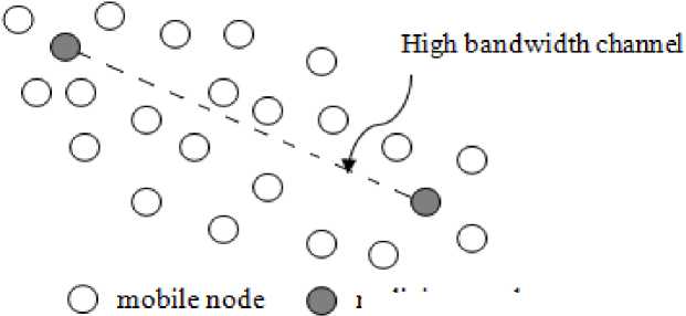
Wormhole attack is a type of attack in which attackers work in collusion and create a tunnel called wormhole tunnel. The colluders silently record packets at one location and tunnel them to another location in the network. If the attack is done using encapsulation called the exposed attack, the path appears to be shorter. If the attack is done using an out of band channel, the transmission becomes faster and is called the hidden attack. The hidden wormhole attack is shown in Fig. 1. As a result, the malicious path will be selected as the optimal path during the route discovery process and subsequently packets routed through that path can be modified, dropped, or sniffed to cause DoS attacks.
malicious node
Figure 1. Hidden Wormhole attack
Wormhole Attack Detection
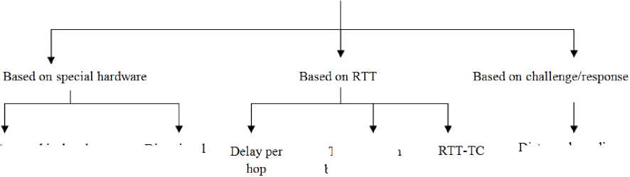
Figure 2. Classification of Wormhole attack detection mechanism
Geographical and Temporal leashes
Directional
Antennas
Distance bounding algorithm
Transmission between every two successive nodes
Contributions in the paper are as follows:
-
• Differentiates wormholes from congested traffic
-
• Pinpoints the location of wormhole
-
• Detects both hidden and exposed attack
-
• Simulation of the proposed system
-
• Reduces the rate of false alarms
Rest of the paper is organized as follows: Section II discusses the various existing methods for detecting the wormholes. Section III gives the motivation for the detection of wormhole attack. Section IV explains our proposed system. Section V gives the simulation results. Section VI concludes the paper.
-
II. Related works
Several approaches have been developed to detect wormhole attacks in Mobile Adhoc Networks. In this section the detection mechanisms shown in Fig. 2 are discussed.
-
A. Based on special hardware
Yih-Chun Hu et al. in [1] presented geographical and temporal leashes for detecting wormholes. A geographical leash requires each node to know its own location and all nodes to have loosely time synchronized clocks. The nodes need to securely exchange location information. A sender node can then ensure that the receiver is within a certain distance and detect discrepancies therein. With temporal leashes, all nodes must have tightly synchronized clocks. The receiver will compare the receiving time with the sending time attached with the packet. It can determine if the packet has travelled too far in too little time and detects the wormhole attack. For the construction of geographical leash, each node must know its own location which requires the need for a Global Positioning system and for temporal leash all nodes must have tightly synchronized clocks. Special hardware is needed to achieve stringent time synchronization between the nodes which makes the setup complex and costly. This approach considers the processing and queuing delays to be negligible and does not take congestion into account.
In [2], directional antennas based on the zone of the arriving signal were proposed to detect wormhole attacks. If a node uses a specific zone of its antenna to communicate with its neighbors, this neighbor should reply using the opposite zone. This method is based on the co-operation between nodes in sharing directional information. This method requires no location information or clock synchronization but requires special hardware with each node and suffers from antennas directional errors.
-
B. Based on RTT
In [3], sender node detects wormhole attack by finding delays of different paths to the receiver. Hop count and delay information of disjoint paths are collected and delay per hop value is computed to serve as an indicator of detecting wormhole attacks. Under normal scenario, the delay that the packet experiences in propagating one hop should be similar along each hop in the path. But, under wormhole attack the delay is unreasonably high due to the presence of malicious nodes along the path. Therefore if a path has high delay per hop value, it is subjected to a wormhole attack. By comparing the delay per hop values among these disjoint paths, a wormhole can be identified. This method prevents both exposed and hidden attack but cannot locate wormhole attack. Since the length of the paths can be changed by every node, wormhole nodes could change the path length in a way that makes them unable to detect.
The authors in [4] detect wormhole attacks during route setup procedure by computing the transmission time between every two successive nodes along the established path. Wormhole is identified based on transmission time between two fake neighbors that is within the radio ranges of each other. Wormhole attacks interfere in the route setup before they cause any damage. TTM requires no special hardware. But as only delays are measured, two legitimate neighbors suffering link congestion is not taken into account and thus suffers from high false alarm rate.
The mechanism developed in [5] called RTT-TC is based on the topological comparison and round trip time measurements (RTT-TC). In this method, a wormhole attack is suspected using RTT measurements and genuine neighbors are excluded from the suspected list using topological comparison. In this method, a Neighbor List includes two segments: Trusted (TRST) and Suspected (SUS). Two nodes suspect a wormhole tunnel between them if the RTT between them is more than 3 times of their current RTT avg . If there is a wormhole tunnel, those two node’s NodeID is inserted to their respective SUS lists. Wormhole detection method is triggered when a source node finds non empty SUS list. A node sends request packets to all nodes in the SUS part of its Neighbor List. In response, the recipients reply back with its TRST list to the source, which is later compared with the TRST list of the source to detect whether a link is attacked by the wormhole. This method has higher detection rate and does not need any clock synchronization but has high message overhead.
-
C. Based on challenge/ response mechanism
Another method in [6] uses a challenge-response system to minimize all possible delays without CPU involvement. Using a distance bounding algorithm, it calculates the distance between two neighbors by sending a one bit challenge and determines if the calculated distance is within maximum possible transmission range. Since they calculate the upper bound on the distance within one hop, they cannot provide solution to exposed wormhole attack problem. This method requires a special hardware that can respond to one bit challenge without delay. Table I summarizes the existing solutions for wormhole attack.
As seen in Sections II. A, II.B, and II.C many of the existing solutions require special hardware or strict synchronized clocks or can cause message overhead. From Table I, it is evident that some solutions do not locate the wormhole attack, generates false alarms, or does not take network congestion into account. Also, some methods detect only one type of wormhole attack. If only RTT between nodes is considered, it may generate false alarms since RTT can increase due to congestion or queuing delays. So a congestion detection mechanism is needed to detect whether the increase in RTT is due to wormhole or congestion. These factors motivated us to propose an efficient detection mechanism for the wormhole attacks.
-
IV. PROPOSED SYSTEM
In this section, the proposed wormhole detection mechanism is discussed in detail. Our proposed system does not require any synchronized clocks or special hardware to detect the wormhole attacks but makes use of its local clock to calculate the RTT between successive nodes on the established path. In the proposed scheme, AODV routing protocol [7, 8, 9] is considered. The proposed method detects wormhole attacks before it causes any harm to the network since wormhole detection is done just after the route setup procedure.
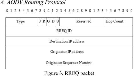
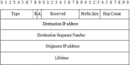
Figure 4. RREP packet
AODV (Adhoc On Demand Distance Vector routing protocol) is an on demand routing protocol. RREQ and RREP packet formats are shown in Fig. 3 and Fig. 4.When a source node wants to send a packet to a destination node and does not have a valid route in its routing table, it broadcasts a RREQ (Route Request) packet. If a node receiving the RREQ is not the destination node or does not have a valid route to the
III. Motivation
destination node, it will re-broadcast the packet and add itself to the path to create a reverse route. Otherwise, a RREP (Route Reply) packet is sent to the source node. The destination node receiving multiple RREPs will respond only to the first RREQ received.
-
B. Modified RREP packet
In our proposed system, a wormhole attack is suspected between two nodes if the RTT between those nodes is greater than or equal to the threshold value. The source node is responsible for calculating the RTT between all the successive nodes in the path established during the route setup procedure. In order to calculate the RTT difference, all the intermediate nodes have to send their RTT values to the source. For this, the RREP packet is modified to carry two additional fields
Table I. Comparison of existing wormhole detection mechanism
|
Detection Method |
Existing Method |
Advantages |
Disadvantages |
||
|
Using specialized hardware |
Packet Leashes-Temporal and Geographical Leashes |
Geographical leash |
Loose time synchronization. Attacker can be caught if it pretends to be in multiple locations. |
Geographical leash |
Need GPS for location information. Cannot detect exposed attack |
|
Temporal Leash |
No need for location information |
Temporal Leash |
Tightly synchronized clocks. Detect only hidden attack |
||
|
Using Directional Antennas |
Need no location information Need no clock synchronization |
Requires directional antennas and suffer from antennas directional errors |
|||
|
Using RTT |
DelPHI |
No need for location or time synchronization Does not require special hardware |
Cannot pinpoint the location of wormhole Does not work well when all paths are tunneled |
||
|
TTM |
No special hardware required Pinpoints the location of wormhole |
Does not take link congestion into account Generate false alarms |
|||
|
RTT-TC |
No need for special hardware or clock synchronization. Higher detection rate |
High message overhead |
|||
|
Using challenge/ response mechanism |
SECTOR |
Requires no location or clock synchronization |
Requires specialized hardware to respond to one bit challenge Cannot detect exposed attack |
||
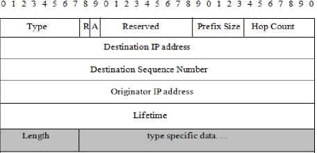
Figure 5. MRREP : RREP packet with additional fields
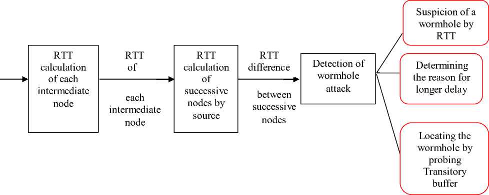
Figure 6. Proposed System
In MRREP packet,
Length = {m x (Hop Count -1)} (1)
Proposed system as shown in Fig. 6 consists of the following modules
-
• RTT calculation of each intermediate node
-
• RTT calculation of successive nodes by source
-
• Detection of wormhole attack
-
C. RTT calculation of each intermediate node
RTT of each node is calculated as the time between a RREQ packet is sent and the corresponding MRREP packet received. In our proposed system, every node ‘X’ maintains a local clock and records the time when it broadcast the RREQ packet (T RREQ (X)). When the node receives the MRREP it saves the time of receiving the reply (T MRREP (X)). It then calculates the RTT as in (2).
RTT(X) = TMRREP (X) - TRREQ (X) (2)
where RTT(X) is the RTT of node X.
Fig. 7 represents the timeline diagram of each node sending RREQ and receiving the MRREP for a normal path. In Fig. 7, S is the source and D is the destination. B,
F and G are the intermediate nodes. Also the time (in ms) of sending and receiving RREQ and MRREP is shown (Time shown is just an example and is not based on the experiments). Each node saves the time of forwarding RREQ packet and receiving MRREP and calculates its RTT as follows
RTT (S) =24-1 =23
RTT (B) = 21-4 = 17
RTT (F) =18-7 = 11
RTT (G) =15-10= 5
Once the RTT is calculated, the intermediate nodes send their RTT values along with the MRREP packet to the source. The destination node will allocate space in MRREP for carrying the RTT on the basis of hop count as explained in Section IV.B
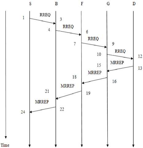
Figure 7. Timeline diagram for RREQ and MRREP of normal path
-
D. RTT calculation of successive nodes by source
The source node gets the RTT values of intermediate nodes from the
RTT (A, B) = RTT (A) - RTT (B) (3)
According to Fig. 7, RTT between successive nodes is calculated as follows
RTT (S, B) = RTT (S) - RTT (B) =23-17=6
RTT (B, F) = RTT (B) - RTT (F) =17-11=6
RTT (F, G) = RTT (F) - RTT (G) =11-5=6
-
E. Detection of wormhole attack
Det ection of wormhole attack is further classified into the following subsystems:
-
• Suspicion of a wormhole by RTT
-
• Determining the reason for longer delay
-
• Locating the wormhole by probing Transitory buffer
E.1. Suspicion of a wormhole by RTT
In our proposed mechanism for wormhole detection, a wormhole attack is suspected if the RTT value between two successive nodes in the path established during the route setup procedure shows considerable difference than between other nodes. The source node is responsible for calculating the RTT between all the successive nodes in the path established. The intermediate nodes embed their RTT value in the
There are two types of wormhole attacks: Hidden attack and Exposed attack. In a hidden attack, there is an out of band high bandwidth channel between the wormhole nodes. The malicious nodes hide that they forward packets. In a hidden attack, the malicious nodes would be located near the sender and the receiver. So the sender and the receiver appear to be immediate neighbors. In an exposed attack, the wormhole nodes are not hidden but there will be a number of nodes in between these malicious nodes through which packet will be encapsulated and sent. In this type of attack, the malicious nodes appear to be neighbors.
E.1.1 Hidden Attack
In a hidden attack, there is a high speed link between the wormhole nodes. The existence of these nodes is not known to other nodes since they hide that they forward packets. Since they are hidden, two fake neighbors appearing to be real neighbors will have a higher RTT than the RTT between true neighbors. Fig. 8 shows the timeline diagram of sending RREQ and receiving RREP through a path under hidden wormhole attack.
In Fig. 8, S is the source, D is the destination and W1 and W2 are the hidden wormhole nodes. The RTT calculations are done as in Section IV.C and IV.D. RTT of each node is calculated as follows
RTT (S) =35-1=34
RTT (A) =32-4=28
RTT (P) = 23-12=11
RTT (Q) =20-15= 5
Now RTT between successive nodes are calculated.
RTT(S, A) =34-28=6
RTT (A, P) =28-11=17
RTT (P, Q) =11-5=6
Here it can be seen that RTT value between A and P is considerably greater than that between other nodes.
E.1.2. Exposed Attack
In an exposed attack, wormhole nodes are not hidden and other nodes know about their existence. But there will be a number of nodes in between these wormhole nodes through which packet will be encapsulated and sent. Thus these wormhole nodes appear to be neighbors and the RTT between these nodes will be higher. Fig. 9 shows the timeline diagram of sending RREQ and receiving MRREP through a path under exposed wormhole attack. In Fig. 9, S is the source, D is the destination. W1 and W2 are the wormhole nodes and X, Y and Z are the nodes in between the wormhole nodes through which the packet is tunneled. The RTT calculations are done as in Sections IV.3 and IV.4. RTT of each node is calculated as follows
RTT (S) =42-1=41
RTT (W1) =39-4=35
RTT (W2) =27-16=11
RTT (J) =24-19=5
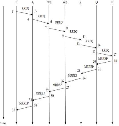
Figure 8. Timeline diagram for RREQ and MRREP for path under hidden wormhole
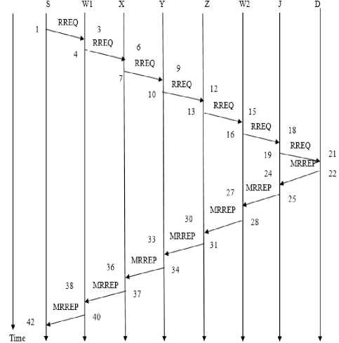
Figure 9. Timeline Diagram of RREQ and MRREP through path under exposed wormhole
E.3. Locating the wormhole by probing Transitory Buffer
Let HHR (Hop with Highest RTT) be the hop at which RTT difference is greater than or equal to the threshold value. {q, p} indicates p is the type of packet and q is a field of p.
Algorithm 1. Pseudo-code for detecting and locating the wormhole
Step 1: Start
Step 2: Source sends a TBREQ packet along the established path
Step 3: : Each node receiving a TBREQ packet
-
3 .a. Generates a TBREP packet containing its Trans_B, copies {hop count, TBREQ} to {Node Number, TBREP} and send it to source.
-
3 .b. Increments
field of TBREQ and forwards it to the next node.
Step 4: for each TBREP if ({node number, TBREP} = HHR)
if ({Trans_B, TBREP} >= MaxTh),congestion else Wormhole detected
Step 5: Stop
RTT between successive nodes are calculated as follows
RTT (S, W1) =41-35=6
RTT (W1, W2) =35-11=24
RTT (W2, J) =11-5=6
Here, RTT value between W1 and W2 is considerably greater than other RTT values.
E.2. Determining the reason for longer delay
A wormhole is suspected if the RTT between two nodes is considerably greater than the RTT between the other nodes in the established path. But RTT can increase due to longer delays caused by congestion or queuing delays and may not always be caused by a wormhole. Therefore a mechanism is needed to detect whether the long delays caused is due to congestion or queuing delays. This mechanism detects congestion at a node level by calculating queue status value and finding congestion status.
Whenever a wormhole is suspected, node’s transitory buffer is probed to determine whether the longer delay is due to congestion or wormhole. For congestion detection [10], we assume that each node in the network maintains a buffer of size buffer_size. For constructing buffer we use the base design of Random Early Detection. The MinTh (Minimum Threshold) and MaxTh (Maximum Threshold) of each buffer is given in (4). Each node maintains a variable called Trans_B (Transitory Buffer) which gives the number of packets currently in its buffer. Trans_B is incremented each time a packet arrives and decremented each time a packet leaves. We assume that the malicious node will update the value of Trans_B correctly and will not change the correct value.
MinTh = 25% buffer_siz e, MaxTh =3*MinTh
To determine whether the longer delay is due to wormhole or congestion, source node compares Trans_B of the TBREP packet with
Each node receiving a TBREQ packet sends a TBREP packet containing their Trans_B to the source. TBREP packet copies the
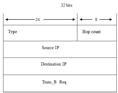
Figure 10. TBREQ packet
32 bits
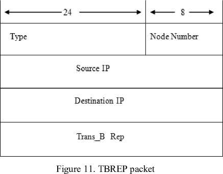
source node, the Trans_B of the packet whose
Fig. 12 shows the flowchart of the proposed system. Our method of detecting wormhole attacks takes place just after the route setup procedure. During the route setup procedure, MRREP carries the RTT of each node in the established path. When MRREP packet reaches the source node, it calculates the RTT between all successive nodes in the established path. If the RTT between two successive nodes (RTT diff ) is greater than or equal to the threshold value, a wormhole is suspected between those links and node’s transitory buffer is probed to determine whether congestion exists since longer delays causing higher RTT may be due to congestion in the network. Otherwise, no wormhole is detected.
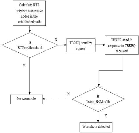
Figure 12. Flowchart for the proposed wormhole detection method
For congestion detection, the source node sends a TBREQ packet along the established path. All the nodes receiving TBREQ packet will send a TBREP packet containing their Trans_B to the source. The source node compares the Trans_B of the packet whose
-
V. Performance Evaluation
-
A. Simulation Setup
Performance of the proposed system is evaluated using NS2 Simulator [11]. The routing protocol used for simulation is AODV. In the simulation, 50 nodes including the wormhole nodes are deployed randomly in a square area of 1200m X 1200m. The nodes may be disconnected at times during network operation due to mobility. The simulation parameters are shown in Table II. Maximum buffer size of each node is set as 64. In the
simulation experiment, three different scenarios are considered: normal scenario, wormhole attack scenario and congestion scenario.
B. Determining the threshold value
In our proposed system, a wormhole attack is suspected if the RTT between two successive nodes in the path established during the route setup is greater than or equal to the threshold value. RTT between two successive nodes is found out by calculating the RTT of each node and subtracting the RTT values. In the simulation experiment, an exposed wormhole attack is implemented by creating a tunnel between the wormhole nodes using encapsulation. The effect of background traffic is not considered while determining the threshold
value. . RTT between successive nodes (RTT diff ) for different path lengths are calculated and the
Table II. Simulation Parameters
-
• The minimum tunnel length is 2 and RTT max when the tunnel length = 2 is greater than the RTT between neighbouring nodes in a normal scenario.
-
• RTT max keeps increasing as tunnel length
increases
-
C. Normal Scenario
In the normal scenario, a source and a destination pair is selected randomly. RTT of each node and RTT difference between successive nodes (RTT diff ) are calculated .There is no significant variation in the RTT values as shown in Fig. 15. The highest RTT difference (RTT high ) between two successive nodes is compared with the threshold. RTT high .is found to be less than the threshold, hence no wormhole.
-
D. Attack Scenario
In the attack scenario, two wormhole nodes are introduced in the path between the source and the destination. These nodes create a tunnel in between them using encapsulation. As in the normal scenario, RTT of each node and the RTT difference is calculated. Due to space limitations, only the result for tunnel length 4 is shown in Fig. 16. Similarly the experiments are conducted for tunnel length 2, 6, 8, 10 and 12. As seen from Fig. 16, the RTT difference at hop 5 is greater than the threshold value and so a wormhole is suspected between 5th and the 4th node from the source.
-
E. Congestion Scenario
In the congestion scenario, background traffic is generated by a random generator. Fig. 18 represents the results when path length= 7, with light and heavy background traffic. It is evident from the figure that RTT difference between most of the successive nodes is greater than the threshold value. Hence a wormhole is suspected. As in the wormhole scenario, the source node probes Trans_B in order to confirm the cause of high RTT. Trans_B of the node with
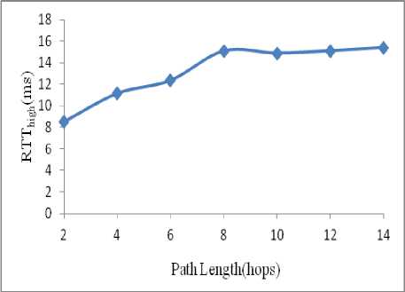
Figure 13. Highest RTT for different path lengths(normal scenario)
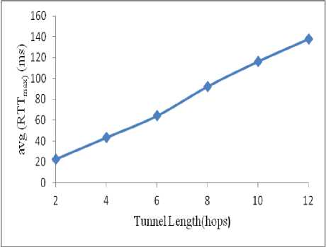
Figure 14. Average of RTTmax for different tunnel lengths (wormhole scenario)
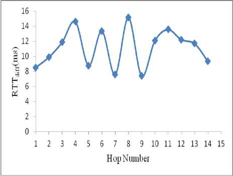
Figure 15. RTT difference between nodes at each hop (normal scenario)
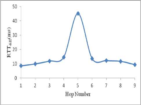
Figure 16. RTT difference between nodes at each hop when tunnel length=4 (wormhole scenario)
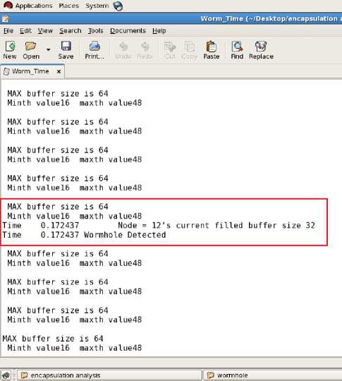
Figure 17. Trans_B of 5th node from source after wormhole is suspected (wormhole scenario)
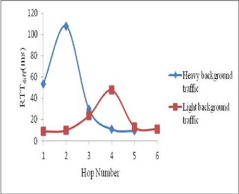
Figure 18. RTT difference between nodes at each hop (congestion scenario)
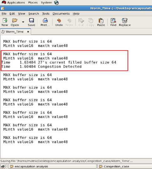
Figure 19. Trans_B of 2nd node from source after wormhole is suspected (congestion scenario)
-
VI. Conclusions
In this paper, various existing methods for the detection of wormhole attacks have been analyzed. Existing methods mostly depend on specialized hardware, strict synchronized clocks, or a special hardware to respond to one bit challenge. Some methods do not detect both types of wormhole (hidden and exposed attack) and results in high false alarms. Our proposed method combines RTT and congestion detection mechanism to detect the wormhole attacks. This method does not require any specialized hardware or synchronized clocks, but pinpoints the location of wormhole. Using NS2, we have simulated normal, wormhole, and congestion scenarios. Using NS2 our proposed system is compared with TTM in the experiments. From experimental results, it is seen that like TTM resulted in false positives as it was unable to detect congestion. But our proposed system detects the presence of congestion and completely eliminates the false positives in detecting the wormhole. Also, by lowering the threshold value it eliminates false negatives in detecting the wormhole. Our proposed system differentiates the rise in RTT due to wormhole and congestion. The simulation has been done for exposed attack. The minimum RTT between two fake neighbors in hidden attack is equivalent to the RTT between the wormhole nodes in exposed attack when the tunnel length is 2. Hence, the proposed system also detects for hidden attack.
References A Novel Solution for Discriminating Wormhole Attacks in MANETs from Congested Traffic using RTT and Transitory Buffer
- Yih-Chun Hu, Adrian Perrig, and David B. Johnson," Packet Leashes: A Defense against Wormhole Attacks in Wireless Networks," In Proceedings of the IEEE Conference on Computer Communications (Infocom), 2003, p. 1976-1986.
- L. Hu and D. Evans, "Using directional antennas to prevent wormhole attacks," In Proceedings of the IEEE Symposium on Network and Distributed System Security (NDSS), 2004
- Hon Sun Chiu and King-Shan Lui, "DelPHI: Wormhole Detection Mechanism for Ad Hoc Wireless Networks," International Symposium on Wireless Pervasive Computing (ISWPC), 2006.
- T Phuong Van Tran, Le Xuan Hung, Young-Koo Lee, Sungyoung Lee, and Heejo Lee, "Transmission time-based mechanism to detect wormhole attack," In Proceedings of the IEEE Asia-Pacific Service Computing Conference, Dec. 11-14, 2007, p. 172-178.
- Mohammad Rafiqul Alam and King Sun Chan, "RTT-TC: A Topological Comparison Based Method to Detect Wormhole Attacks in MANET," 12th IEEE International Conference on Communication Technology, 2010, p. 991-994.
- S. Capkun, L. Buttyan, and J.P. Hubaux., "SECTOR: Secure tracking of node encounters in multi-hop wireless networks," In Proceedings of the 1st ACM workshop on Security of ad hoc and sensor networks (SASN 03), 2003, p.21–32.
- Rutvij H. Jhaveri, Ashish D. Patel, Jatin D. Parmar, and Bhavin I. Shah, "MANET Routing Protocols and Wormhole Attack against AODV," International Journal of Computer Science and Network Security (IJCSNS), vol 10 No.4, April 2010, p. 12-18.
- Amrit Suman, Praneet Saurabh, and Bhupendra Verma, "A Behavioral Study of Wormhole Attack in Routing for MANET," International Journal of Computer Applications (0975 – 8887), vol 26 No.10, July 2011, p. 42-46.
- C. Perkins, E. Belding-Royer, and S. Das, "Ad hoc On-Demand Distance Vector (AODV) Routing," RFC 3561, IETF Network Working Group, July 2003.
- T. Senthil kumaran, Dr. V Sankaranarayanan, "Early detection Congestion and Control Routing in Manet," In Proceedings of Seventh International Conference on Wireless and Optical Communication Networks, Sept 2010, p 1-5.
- Ns2 simulator http://www.isi.edu/nsnam/ns/.
