A Novel VideoTransmission Evaluation Framework based on TCP-Friendly Congestion Control Mechanism

Author: Xiao fu, Hu Ting, Yu JianPing, Sun Lijuan, Wang RuChuan
Journal: International Journal of Computer Network and Information Security(IJCNIS) @ijcnis
Article in issue: 2 vol.2, 2010.
Free access
TFRC protocol is suitable for video transmission in a wire network, and quality assessment is also essential in a video transmission system. In this paper, a real-time video transmission system based on TFRC protocol is proposed, and the evaluation model about the system is improved in the framework of Evalvid. It assesses the quality and efficiency of the video transmission according to the actual video file, and analyzes losses frame in different video types during transmission as well as the video quality in receiver. The results of simulation experiment in NS-2 show that when real-time video transmitted in wire network environment using this system, the receiver can get satisfactory video quality by reason of the TFRC protocol friendliness and the smoothness of sending rate. Based on the characteristic of high error rate in wireless network, the novel TCP friendly congestion control algorithm TFRC-JI proposed in our previous work [1] was adopted, which introduces the latency vibration to distinguish the link congestion from code error, thus different speed control mechanism is feedback to the transmitting end. Simulation experiment results indicated that compared with the traditional TFRC, the TFRC-JI suites well for real-time service transmission.
TFRC, Quality evaluate, NS2, Congestion control, Streaming video
Short address: https://sciup.org/15010991
IDR: 15010991
Text of the scientific article A Novel VideoTransmission Evaluation Framework based on TCP-Friendly Congestion Control Mechanism
Published Online December 2010 in MECS
Recently more telecommunication systems are supporting different kinds of real-time transmission, and video transmission is one of the most important applications. This increasing deployment causes the quality of the supported video to become a major issue. TCP has a congestion control mechanism of halving its rate, which makes data transmission rate fluctuate badly, while UDP does not have any congestion control mechanism, which means UDP flows will occupy too much bandwidth over TCP flows. At the same time increase its own package losses when the network is congested and make the network environment even worse. So both TCP and UDP are not suitable for real-time streaming application. TCP Friendly Rate Control (TFRC) is an equation based congestion control technique for best effort networks that provides a smoother throughput variation over time, which make it more suitable for multimedia streaming applications.
Packet losses are the only congestion sign in the current internet. However, some links, such as wireless and satellite links, are characterized by high link error rates and thus, packet loss can occur due to link errors. TFRC assumes that packet loss in wire networks is primarily due to congestion, and as such is not directly applicable to wireless networks in which the main cause of packet loss is at the physical layer. TFRC can’t distinguish between packet loss due to buffer overflow and that due to physical channel errors, resulting in underutilization of wireless bandwidth. Hence streaming rate control and congestion control mechanism over wireless are still open issues. Consequently, there have been a number of efforts to improve the performance of TFRC over wireless links. To gain a better understanding of the spectrum of approaches to rate control over wireless, we briefly review TFRC solutions over wireless.
Recently, some schemes have been proposed to address this issue. TFRC-ASN [2] is designed to discriminate wireless losses from congestion losses when the receiver estimates the packet loss interval, which used Additional Sequence Number (ASN) to count the number of packets sent over wireless link. In contrast to existing schemes, TFRC-ASN can discriminate accurately wireless losses and also packet error rate can be estimated in wireless link. WM-TFRC [3] uses the access point (AP) in wireless LAN to measure the rate of wireless loss events and feeds back to the sender periodically. Meanwhile, the receiver also provides feedback about the rate of total loss events (including wireless loss and congestion loss) to the sender. Therefore, the sender can deduce the rate of congestion loss events. It can eliminate the effect of wireless losses in flow control and substantially reduce the abrupt quality degradation of the video streaming caused by the unreliable wireless link status. Arya proposed Accurate and Explicit Differentiation (AED) [4] by assuming that agents are deployed before and after each wireless link. AED aims to inform the TFRC receiver about wireless and congestion losses so that it can send an accurate feedback to the sender. The agents snoop through each packet and detect a loss by finding a packet with an out-of-order sequence number. ECN-based TFRC [5] refine the well-known Floyd's TCP throughput model by taking into account the dormant period followed by each congestion window reduction in the congestion avoidance phase. ECN-marked packet is used as a congestion indicator and the TCP-friendly rate is computed using the refined TCP throughput model. ECN-based TFRC effectively eliminate the effect of wireless losses. It significantly improves the quality of delivered video in a wireless environment, compared with the conventional loss-based TCP-friendly flow control scheme.
All the above proposals try to differentiate non-congestion losses from congestion losses and mask them from the calculation of sending rate. However, all of them require the supports from the intermediate nodes, which are not easy to be deployed in the existing network facilities. In our previous work [1], an end-to-end enhancement of TFRC is proposed. Specifically, our enhancement distinguishes non-congestion losses and congestion losses. Non-congestion losses will make less contribution to the calculation of the sending rate than congestion losses do. Our simulation results show that, such modification can improve TFRC performance over wireless networks. Furthermore, it does not require any supports from the intermediate nodes.
Jirka Klaue[6] presented a complete framework and tool-set for evaluation of the quality of video transmitted over a real or simulated communication network firstly. Besides QoS parameters and subjective video quality of the received video is evaluated based on the frame-by-frame PSNR calculation. Chih-Heng[7] extend the connecting interfaces of EvalVid to replace its simple error simulation model by a more general network simulator like NS2.With this combination, researchers and practitioners in general can analyze through simulation the performance of UDP video streams. However UDP flows will occupy too much bandwidth over TCP flows and increase its own package losses when the network is congested.
Based on these above research works, we present a real-time video transmission system based on TFRC-JI protocol and an evaluation model about the system in the framework of EvalVid. The rest of this paper is organized as follows: Section 2 introduces the basic mechanism of TFRC-JI we presented and the EvalVid which is the framework and toolkit for a unified assessment of the quality of video transmission. And the QoS assessment framework for video traffic enabled by the new tool-set that combines EvalVid and NS2 is proposed in section 3. To evaluate the system and model, experiments are conducted in section 4. The paper concludes with section 5.
-
II. BASIC MECHANISM OF TFRC AND OVERVIEW OF EVALVID
-
A. Basic mechanism of TFRC and TFRC-JI
In order to compete fairly with the majority TCP traffic in the Internet, the concept of TCP-friendly was created [8] where the generated network traffic has a behavior close enough to that of TCP traffic in similar conditions thus inheriting the congestion control properties of TCP. The rate-based congestion control of a TCP-friendly flow does not aggressively find and use available bandwidth, but maintains a relatively stable sending rate while still being responsive to congestion.
The basic mechanism of traditional TFRC can be characterized as follows:
The friendliness TFRC keeps to TCP is achieved by using the TCP throughput equation directly. Basically, the process includes these four steps:
-
1) Measure the loss event rate at the receiver, and feed it back to the sender.
-
2) Measure the RTT (Round Trip Time) using the feedback information at the sender.
-
3) Calculate the current permitted transmit rate keeping TCP friendliness using the throughput congestion.
-
4) Update the transmit rate according to the result of comparison of the calculated one with the current one.
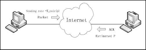
Figure 1. Basic mechanism of TFRC
In order to derive an acceptable TCP-friendly transmission, the TFRC sender adjusts its transmission rate based on the measured loss rate and RTT. Using TCP throughput model, a control equation has been derived for the use of the adjustment of sending rate to achieve TCP-friendliness. The control equation is:
S (1)
X_calc =-------. --------j=----------- v 7
RTT(t^2bp + t^ (3^3|p)p (1 + 32p2)
Here, X calc is the upper limitation of calculated throughput in B/s, s is the size packet in bytes, RTT (t) is the round trip time in seconds, b is the number of packets the TCP receiver acknowledges for one time, usually equal 1, p is the stable state loss event rate, is the TCP , p , tRTO retransmission time out value in seconds, the bigger one of 4R and 1 second [9-11].
The calculation of the loss event rate at the receiver is one of critical parts of TFRC. The Average Loss Interval method computes a weighted average of the loss rate over the last n loss intervals. The principle can be described as follows: The receiver judges a packet is lost when three packets with higher sequence number than it arrived. The term loss event refers to several packets lost within one round-trip time. Note that the subsequent losses following the first loss in the round-trip time are ignored, i.e., at most one loss event in one round-trip time. The term loss interval is defined as the number of packets between loss events. The value of a loss interval is obtained by subtracting the sequence number of the first lost packet in a loss event from the sequence number of the firs lost packet in the subsequent loss event. The use of a weighted average by the Average Loss Interval method reduces sudden changes in the calculated rate that could result from unrepresentative loss intervals. In TFRC, the receiver uses the method, history discounting with the Average Loss Interval, to smooth the oscillation of transmission rate in order to make a TFRC flow more stable.Figure2 illustrates the relationship between loss events and loss intervals [12].
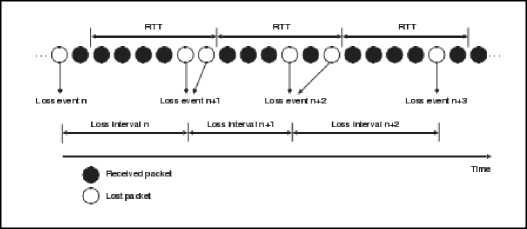
Figure 2. An example of loss events.
Let Ai be the with recent loss interval, and Wi be the weight of Ai .The receiver calculates the average loss interval of the recent n loss intervals as follows:
A = twtAt[tw (2)
In TFRC, the default value of n is 8, and w1=w2=w3=w4=1, w5=0.8, w6=0.6, w7=0.4, w8=0.2.
Finally, the loss event rate, p, is given by p = 1 A (3)
TFRC is an equation based congestion control technique for best effort networks that provides a smoother throughput variation over time, making it more suitable for streaming multimedia applications.
Delay jitter is the transfer delay difference of two neighboring packets in one connection. If we set Si as the send time of Packet i, Ri as the arrive time of packet i, then the delay jitter of the two neighboring packets ( i , i+1 ) can be described as
D(i,i+1)=(Ri+1-Si+1)-(Ri-Si) (4)
Delay jitter from the formula shows that, while D =0,the delay of the packet i and i+1 is equal; If D>0, the delay of the packet i+1 is longer than packet i, which means packet i+1 was queuing processing in the network. Thus delay jitter can be treated as a divisional of the lost package reason. When the jitter is larger than the setting threshold value, it means the current network is in the congestion state, and loss events is caused by congestion; otherwise, packet loss is caused by physical channel errors,
TFRC-JI introduced a new method of statistical package interval. Whether current delay jitter exceed the threshold can be used as the judgments of loss package reasons, and make adjustments by the current lost package interval. When delay jitter is larger than the setting threshold K, it means the current network is in the congestion state, so we reduce the current loss package interval according to a certain proportion of factors in order to increase loss package incident rate P. Due to the incensement of the value of p, the sender reduce its sending rate, so as to achieve the purpose of congestion control. When delay jitter is smaller than the setting threshold K, it means the current network is not in the congestion state, and the current loss package is caused by bit error, so we increase the current loss package interval according to a certain proportion of factors in order to increase the current sending rate. Finally, we achieve the purpose of improving throughput rate.
-
B. Overview of EvalVid
Publicly available tools for video quality evaluation often assume synchronized frames at the sender and the receiver side, which means they can’t calculate the video quality in the case of frame drops or frame decoding errors. In this paper we first introduce EvalVid, a framework and a toolkit for a unified assessment of the quality of video transmission. EvalVid has a modular structure, making it possible to exchange at users discretion both the underlying transmission system as well as the codec’s, so it is applicable to any kind of coding scheme, and might be used both in real experimental setups and simulation experiments.
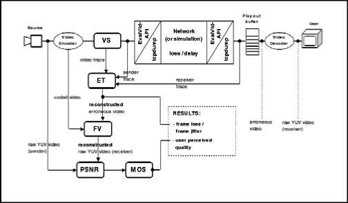
Figure 3. Schematic illustration of the evaluation framework
The main components of the evaluation framework are described as follows:
Source : The video source can be either in the YUV QCIF (176×144) or in the YUV CIF (352×288) formats.
Video Encoder and Video Decoder: Currently, EvalVid only supports single layer video coding. It supports three kinds of MPEG4 codecs, namely the NCTU codec, ffmpeg, and Xvid. The focus of this investigation is NCTU codec for video coding purposes.
VS (Video Sender): The VS component reads the compressed video file from the out-put of the video encoder, fragments each large video frame into smaller segments, and then transmits these segments via packets over a real or simulation network. For each transmitted packet, the framework records the timestamp, the packet ID, and the packet payload size in the sender trace file with the aid of third-party tools, such as tcp-dump or win-dump, if the network is a real link. Nevertheless, if the network is simulated, the sender trace file is provided by the sending entity of the simulation.
ET (Evaluate Trace): The heart of the evaluation framework is a program called ET (evaluate traces).Here the actual calculation of packet and frame losses and delay/jitter takes place. For the calculation of these data only the three trace files are required,since there is all necessary information included to perform the loss and jitter calculation,even frame/packet type based.The calculation of loss is quite easy,considering the availability of unique packet id’s. With the help of the video trace file,every packet gets assigned a type.Every packet of this type not included in the receiver trace is counted lost.Frame losses are calculated by looking for any frame,if one of it’s segments(packets)got lost and which one.If the first segment of the frame is among the lost segments,the frame is counted lost.This is because video decoder cannot decode a frame.
PSNR (Peak Signal Noise Ratio): PSNR is one of the most widespread objective metrics to assess the application-level QoS of video transmissions. The following equation shows the definition of the PSNR between the luminance component Y of source image S and destination image D: N col N row
PSNR ( n ) dB = 20logtoW ek 4 1 NC0Nr w ZD Y ( n,i , j ) - Y d ( ni , j )] 2 ] / i = 0 j = 0
Where V peak = 2k - 1 and k equal the number of bits per pixel (luminance component). Since the PSNR is calculated frame by frame it can be inconvenient, when applied to videos consisting of several hundred or thousand frames.Furthermore, people are often interested in the distortion introduced by the network alone.So they want to compare the received (possibly distorted) video with the undistorted video sent.This can be done by comparing the PSNR of the encoded video with the received video frame by frame or comparing their averages and standard deviations.
MOS (Mean Opinion Score): MOS is a subjective metric to measure digital video quality at the application level. This metric of the human quality impression is usually given on a scale that ranges from 1(worst) to 5(best) [13-15].In this framework; the PSNR of every single frame can be approximated to the MOS scale using the mapping shown in table I.
TABLE I. possible PSNR to MOS conversion
|
PSNR[dB] |
MOS |
|
>37 |
5(Excellent) |
|
31-37 |
4(Good) |
|
25-31 |
3(Fair) |
|
20-25 |
2(Poor) |
|
<20 |
1(Bad) |
-
III. New Network Simulation Agents
Fig.4 illustrates the QoS assessment framework for video traffic enabled by the new tool-set that combines EvalVid and NS2. As shown in Fig.4, three connecting simulation agents, namely myEvalvid, myTfrc, myfrc-Sink is implemented between NS2 and EvalVid. These interfaces are designed either to read the video trace file or to generate the data required to evaluate the quality of delivered video.
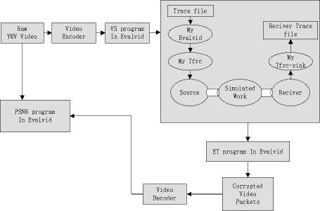
Figure 4. Interfaces between EvalVid and NS2
Consequently, the whole evaluation process starts from encoding the raw YUV video, and then the VS program will read the compressed file and generate the traffic trace file. The myEvalvid extracts the frame type and the frame size of the video trace file generated from the traffic trace file, fragments the video frames into smaller segments, and sends these segments to the lower MyTfrc layer at the appropriate time according to the user settings specified in the simulation script file. MyTfrc is an extension of the Tfrc agent, this new agent allows users to specify the output file name of the sender trace file and it records the timestamp of each transmitted packet, the packet ID, and the packet payload size. The task of the MyTfrc agent corresponds to the task that tools such as tcp-dump or win-dump performs in a real network environment.
MyTfrc-Sink is the receiving agent for the fragmented video frame packets sent by MyTfrc. This agent also records the timestamp, packet ID, and payload size of each received packet in the user specified receiver trace file. After simulation, based on these three trace files and the original encoded video, the ET program produces the corrupted video file. Afterward, the corrupted video is decoded and error concealed. Finally, the reconstructed fixed YUV video can be compared with the original raw YUV video to evaluate the end-to-end delivered video quality.
-
IV. SIMULATION RESULTS
Fig.5 presents the simple simulation topology, in which Host A delivers a video traffic stream to Host B through routers R1 and R2. The delivered video is a “foreman” QCIF format sequence composed of 400 frames. The bottleneck link has a capacity of 180 Kbps and is situated between router R1 and router R2. The queue limit at each router is set to 10 packets.
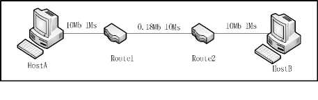
Figure 5. Simulation topology
Experiments are carried out in three steps. First we use UDP as a transport layer protocol. Secondly, MyTfrc is used and thirdly we use MyTfrc-JI. The comparison of the data which use the above three different protocols are showed in the Table II and Figure 6.
TABLE II. packet loss and frame loss
|
I |
P |
B |
|
|
ALL |
|||
|
Frame |
Frame |
Frame |
|
|
Packet |
|||
|
Video sent 548 |
173 |
109 |
266 |
|
Source Frame 400 |
45 |
89 |
266 |
|
sent |
|||
|
Packet |
|||
|
lost 70 |
49 |
14 |
7 |
|
Udp Frame 43 |
23 |
13 |
7 |
|
lost |
|||
|
Packet |
|||
|
, , гт. о lost 10 |
4 |
1 |
5 |
|
MyTfrc os Frame 7 |
1 |
1 |
5 |
|
lost |
|||
|
Packet |
|||
|
,, „ lost 6 |
4 |
0 |
2 |
|
MyTfrc-JI ost Frame 3 |
1 |
0 |
2 |
|
lost |
Table III presents frame images from 210th frame to 214th frame with UDP, MyTfrc separately. The results of simulation experiment in NS2 show that when this system transmits real-time video in network environment, the receiver can get satisfactory video quality by reason of the protocol friendliness and the smoothness of sending rate of TFRC.
TABLE III. frame images from 210 to 214
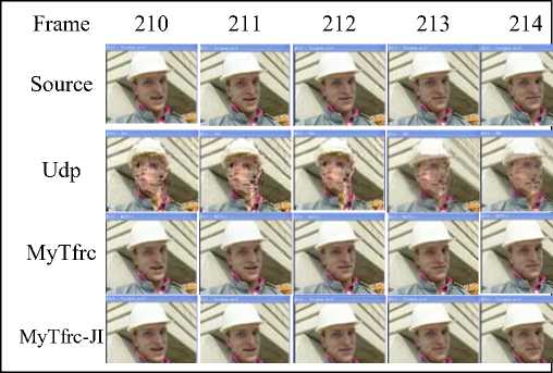
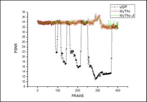
Figure 6. PSNR comparision of frame image under UDP and MyTfrc
In wireless networks however, packet loss can also be caused by physical channel errors. TFRC can’t distinguish between packet loss due to buffer overflow and that due to physical channel errors, resulting in underutilization of wireless bandwidth. Hence streaming rate control and congestion control over wireless are still open issues.
In our previous work [1], we proposed an end-to-end enhancement of TFRC. Specifically, our enhancement distinguishes non-congestion losses and congestion losses. Non-congestion losses will make less contribution to the calculation of the sending rate than congestion losses do. Our simulation results show that, such modification can improve TFRC performance over wireless networks. Furthermore, it does not require any supports from the intermediate nodes.
Experiments are carried out in wireless environment, and we set error rate ER= 0.0001, 0.00001 and 0.000001.
TABLE IV. ERROR RATE = 0.000001 packet loss and frame
LOSS
|
ER= 0.000001 |
ALL |
I Frame |
P Frame |
B Frame |
|
|
Packet |
|||||
|
Video |
sent |
548 |
173 |
109 |
266 |
|
Source |
Frame sent Packet |
400 |
45 |
89 |
266 |
|
MyTfrc |
lost |
17 |
8 |
3 |
6 |
|
Frame lost Packet |
11 |
2 |
3 |
6 |
|
|
MyTfrc-JI |
lost |
9 |
4 |
1 |
4 |
|
Frame lost |
6 |
1 |
1 |
4 |
|
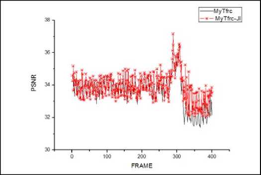
Figure 7. ERROR RATE = 0.000001 PSNR comparision of frame image under MyTfrc and MyTFRC-JI
TABLE VI. ERROR RATE = 0.0001 packet loss and frame loss
|
ER= 0.0001 |
ALL |
I Frame |
P Frame |
B Frame |
|
|
Video |
Packet sent |
548 |
173 |
109 |
266 |
|
Source |
Frame |
400 |
45 |
89 |
266 |
|
MyTfrc |
sent Packet lost |
100 |
35 |
16 |
49 |
|
Frame |
73 |
8 |
16 |
49 |
|
|
MyTfrc-JI |
lost Packet lost |
58 |
22 |
11 |
25 |
|
Frame |
41 |
5 |
11 |
25 |
|
|
lost |
|||||
TABLE V. ERROR RATE = 0.00001 PACKET LOSS AND FRAM
|
ER= 0.00001 |
Packet |
ALL |
I Frame |
P Frame |
B Frame |
|
Video |
sent |
548 |
173 |
109 |
266 |
|
Source |
Frame sent Packet |
400 |
45 |
89 |
266 |
|
MyTfrc |
lost |
23 |
8 |
5 |
10 |
|
Frame lost Packet |
17 |
2 |
5 |
10 |
|
|
MyTfrc-JI |
lost |
11 |
4 |
2 |
5 |
|
Frame lost |
8 |
1 |
2 |
5 |
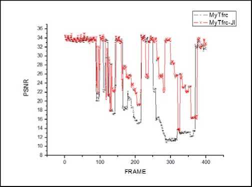
Figure 9. ERROR RATE = 0.0001 PSNR comparision of frame image under MyTfrc and MyTFRC-JI
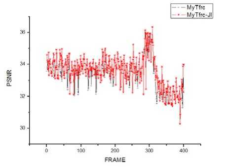
Figure 8. ERROR RATE = 0.00001 PSNR comparision of frame image under MyTfrc and MyTFRC-JI
-
V. CONCLUSION
This paper analyzes the real-time transport of MPEG-4 video based on UDP and TFRC. Simulation results show that TFRC protocol is very suitable for video transmission in a wire network, and quality assessment is also essential for a video transmission system. It assesses the quality and efficiency of the video transmission according to the actual video file, and analyzes different types of video frame losses during transmission as well as the picture quality in receiver. In wireless networks, however, packet loss can also be caused by physical channel errors . Based on the characteristic of high error rate in wireless network, a novel TCP friendly congestion control algorithm TFRC-JI [1] was quoted in this article, which introduces the latency vibration to distinguish the link congestion from code error, thus different speed control mechanism is feedback to the transmitting end. Simulation experiment results indicated that compared with the traditional TFRC, the TFRC-JI suites well for real-time service transmission.
Acknowledgment
We are grateful that this subject is sponsored by the National Natural Science Foundation of China(61003236 、 60973139 、 60773041 、 60903181 、 60903168); Doctoral Fund of Ministry of Education of China (20103223120007)); Science and Technology Support Program Project of Jiangsu Province(BE2010197, BE 2010198); The Six Kinds of Top Talent of Jiangsu Province (2008118); The Science & Technology Innovation Fund for Higher Education Institutions of Jiangsu Province(CX10B-196Z, CX10B-197Z, CX10B-198Z, CX10B-200Z), etc.
References A Novel VideoTransmission Evaluation Framework based on TCP-Friendly Congestion Control Mechanism
- XIAO Fu,WANG Ru-chuan,SUN Li-juan,WANG Hua-shun . Research of TCP-friendly Congestion Control Protocol in Wireless Network[J]. Computer Science. 2010, 3(7):.50-53.
- Lee.H,Choi,Chong.H, A loss discrimination scheme for TFRC in last hop wireless networks[C].IEEE Wireless Communications and Networking Conference, WCNC, 2007:3084-3088
- J.Y.Pyun,Y.Kim,K.H.Jang,J.A.park, S.J.Ko.Wireless Measurement Based Resource Allocation for QoS Provisioning over IEEE 802.11 Wireless LAN[J]. IEEE Trans.on Consumer Electronics,vol.49, pp.1103-1127.2003.
- V.Arya,and T.Turletti.Accurate and Explicit Differentiation of Wireless and Congestion Losses[C].in Proceedings of International Conference on Distributed Computing Systems Workshops(ICDCSW’03), 2003.
- S.J.Bae,and S.Chong.TCP-Friendly Flow Control of Wireless Multimedia using ECN Marking[J]. Signal Processing:Image Communication,vol.19,pp.405-419,2004.
- J.Klaue,B.Rathke,and A.Wolisz.EvalVid-A framework for video transmission and quality evaluation[C].Proceedings of the International Conference on Modelling Techniques and Tools for Computer Performance Evaluation,2003:pp..255-272.
- Chih-Heng,Ce-KuenShieh,Wen-Shyang,Hwang,Artur-Ziviani.An Evaluation Framework for More Realistic Simulations of MPEG Video Transmission[J].Journal of Information Science and Engineering, 2008, 24(2):425-440.
- Widmer,J.;Denda,R.;Mauve,M. A survey on TCP-friendly congestion control[J], Network,IEEE,vol.15,no.3,pp.28-37,May 2001
- S.Floyd and K.Fall.“Promoting the use of end-to-end congestion control in the Internet[J].IEEE/ACM Transactions on Networking, 7(4):458–472,1999.
- Floyd S,Handley M,Padhye J,et al.TCP Friendly Rate Control(TFRC):Protocol Specification.Network Working Group RFC 3448[R],2003-01.
- M.Handley,S.Floyd,J.Padhye,J.Widmer,TCP Friendly Rate Control(TFRC): Protocol Specification Network Working Group, RFC 5348, 2008-09.
- Bin Zhou, Cheng Peng Fu, et al “An enhancement of TFRC over wireless networks[C]. IEEE Wireless Communications and Networking Conference, WCNC, pp.3021-3026, 2007
- A. Lie, J. Klaue.Evalvid-RA:Trace Driven Simulation of Rate Adaptive MPEG-4 VBR Video[J]. Multimedia Systems,2007:pp1-13.
- F.H.P.Fitzek,M.Reisslein,MPEG-4 and H.263 video traces for network performance evaluation[J].IEEE Network, 2001: pp40-54.
- M.F.Alam,M.Atiquzzaman,and M.A.Karim.Traffic shaping for MPEG video transmission over the next generation internet[J],Computer Communications.2000.
