A programmable and managed software defined network

Author: Priyesh Kumar, Rajnarayan Dutta, Rakesh Dagdi, Kavitha Sooda, Archana Naik
Journal: International Journal of Computer Network and Information Security @ijcnis
Article in issue: 12 vol.9, 2017.
Free access
Software Defined Networking is a paradigm-shifting technology in the field of computer networking. It empowers network administrators by giving them the ability to manage the network services through abstraction of the low-level network functionalities. This technology simplifies networking and makes it programmable. This paper presents an implementation of this new paradigm of networking, which can replace the currently existing legacy networking infrastructure to provide more control over the network, perform a better analysis of the network operation and hence program the network according to the needs of the network administrator. This implementation also empowers the network administrators to provide Quality of Service to its users that are connected to the network and uses the services of the network. Therefore, it benefits both the network administrator and the users. Also, the ping latency in the network is reduced by 5-10%, and the number of packets in is reduced by 60-70% in the solution developed depending on the size of the network.
Network management, OpenFlow, Quality of Service (QoS), RYU SDN Controller, SDN
Short address: https://sciup.org/15015558
IDR: 15015558 | DOI: 10.5815/ijcnis.2017.12.02
Text of the scientific article A programmable and managed software defined network
Published Online December 2017 in MECS
The conventional architecture of computer networks that facilitate the current day operation of the internet and is prevalent in most of the implementations use switches and routers that are autonomous in their working. Each switch has its control plane and data-forwarding plane embedded into one, which autonomously makes the forwarding decisions and forwards the packets to its destination. When switches or routers gets connected to a computer network, it performs actions like the construction of a spanning tree to avoid the formation of cycles in the network and to determine its neighbouring nodes in that network. Messages are exchanged to pass information of their neighbours and resulting topologies to the other nodes. Therefore, each node has some idea of the topology of which it is a part.
However, the legacy approach has certain drawbacks, which are as follows:
-
i. To setup topology, the networking devices need determining the neighbouring nodes, and construction of spanning tree, which leads to routers requiring a lot of processing capability. It results in expensive routers and switches. A certain amount of time is also required to identify loop-free topology and the neighbouring nodes [1]. ii. Since a conventional switch or router can have the information of only a part of the network, it can lead to poor routeing decisions and hence can be a bottleneck in the performance of the network.
-
iii. Due to advancements in processor technology every year, which offers higher computational capabilities at lower costs, makes the existing infrastructure obsolete. Legacy hardware is unable to provision the Packet Flow, and Throughput needed to meet the ever-increasing bandwidth requirements, compared to new hardware. At present, replacing the entire router or switch is the only option for network operators, which is not feasible from the Operating expense [2] and Capital expenditure [3] point of view.
-
iv. Devices such as routers and switches are compliant with industry standards only to a certain level, and beyond that, these products are developed by different vendors to meet the requirements in a non-standard way. This practice leaves little room for development and leads to vendor locked networks.
Software Defined Networks (SDN) got introduced to overcome the drawbacks of legacy networks. This new paradigm in computer networks promises to overcome the barriers, to make the network more programmable, efficient, and secure.
The idea behind SDN is to separate the control and data forwarding plane. In other words, decoupling the two planes. Now if the functioning of the two planes is kept independent, then each plane can be optimised independently, resulting in an increased efficiency.
OpenFlow is a standard-based protocol, which allows a centralised controller to monitor and manage the network. OpenFlow provisions the controller to be able to communicate with multiple vendor devices, various types of hardware (routers, switches, load balancers and others), using a standard interface. It also enables the control logic to decide on how to perform packet forwarding and packet rules to be put down into a hardware abstraction, where the individual network device can follow them [4].
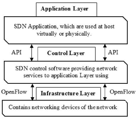
Fig.1. The SDN System Architecture [5]
The above figure (Fig. 1) contains a graphical representation of the SDN architecture as envisioned by the Open Networking Foundation (ONF). The following section explains the figure.
SDN architectures have three components or groups of functionality [5]:
-
i. Application Layer : Application layer consists of programs that communicate behaviours and needed resources with the SDN Controller via application programming interface (APIs). Also, the applications can build an abstracted view of the network by collecting information from the controller for decision-making purposes. Example for SDN applications would be an application built to recognise suspicious network activity for security reasons.
-
ii. Control Layer : It consists of the SDN Controller that is a program, which acts as an intermediary between the SDN applications and networking components. Its functions involve relaying the
instructions received from the application layer to the networking components and extracting information about the network from the hardware devices and communicating it back to the SDN Applications which includes statistics and events that take place in the networking devices.
-
iii. Infrastructure Layer : It consists of the SDN networking devices that are the devices, which have forwarding and data processing capabilities for the network to operate. It includes switches with only the forwarding plane like OpenFlow switches.
-
II. Advantages Of SDN Approach
SDN centralises the functionality of network management and makes network administration effortless by providing efficient network management with proper analytics. A centralised controller can accomplish programming of the network, load balancing and prioritisation of packets and hence be saving time and resources. It has a great scope in upcoming technologies like enterprise cloud, and distributed computing, as better networks lead to its efficient use.
SDN offers the following advantages over the conventional networking approach:
-
i. Since the control plane gets decoupled from the data plane, the switches/routers become very simple in functionality. They need to forward a packet to a port based on the flow installed in the forwarding table by the controller.
-
ii. The switches/routers only need a multiplexing circuit to carry out the packet forwarding. There is no requirement for significant computation power as in conventional networks.
-
iii. Since only the controller needs to know the topology, it saves a considerable amount of time, as the nodes in the network do not need to discover all the other nodes in the network except their neighbours.
-
iv. Optimisation of both planes is possible independently.
-
v. Paths need not be pruned between two nodes to avoid cycles. In fact, they can be used to increase the throughput of the network or in the case of link failures.
-
vi. This approach is easy to scale, and no complicated configuration is needed.
-
vii. Most importantly, a centralised control plane allows us to make forwarding decisions centrally across the domain of the SDN rather than at each hop in the network.
-
III. Related Work
Some of the key ideas of SDN are the introduction of dynamic programmability in forwarding devices through open southbound interfaces, the decoupling of the control and data plane, and the global view of the network by logical centralization of the “network brain”. While data plane elements became dumb but on the other hand, they have become highly efficient and programmable packet forwarding devices. The controller, a single entity, now represents the control plane elements. Applications implementing the network logic run on top of the controller and are much easier to develop and deploy when compared to traditional networks [3].
-
H. Kim and N. Feamster in [6] shows that SDN is an emerging networking paradigm that gives hope to change the limitations of current network infrastructures. First, it breaks the vertical integration by separating the network’s control logic (the control plane) from the underlying routers and switches that forward the traffic (the data plane). Second, the disaggregation of the control and data plane makes the network switches only a simple forwarding device, and the control logic is moved to a logically centralised controller, simplifying policy enforcement and network configuration [6].
SDN has successfully created an innovative research and development environment, promoting the advances in several areas. These can pertain to design of switches and controller platforms, development in scalability and performance of various devices and architectures, and improvement in security of networks. Emerging topics that require further research are extending SDN towards carrier transport networks, the realisation of the network-as-a-service cloud-computing paradigm, or software-defined environments (SDE).
-
IV. Implementation
In this implementation of SDN for better and programmable networks, the developed Web-based Network Management System enables network engineers and administrators to centrally manage and control the network from anywhere in the scope of the network.
This implementation uses RYU SDN controller [7] as the network operating system, which in collaboration with modern and sophisticated web technologies creates a user-friendly Network Management System.
The system monitors network devices, nodes, connectivity, traffic and many more events as well as basic configurations of devices.
The system is a collaboration of three layers as envisioned by ONF:
-
i. Control layer:
-
- RYU SDN controller is used as the control software in the implementation.
-
- When there is any activity in the infrastructure layer, the controller generates an event corresponding to it, and these events can be consumed by the applications built upon it.
-
ii. Applications layer:
-
- Control applications to monitor and manage network elements and provide interfacing services
(APIs).
-
- Web application (Dashboard, based on react-material-admin-template [8]) to interact with a controller in the browser.
-
iii. Infrastructure layer:
-
- It consists of the all the physical elements like hosts and OpenFlow switches.
-
4.1. Web Console (Dashboard):
The figure below (Fig. 2) illustrates the architecture of the developed web console and an explanation afterwards.
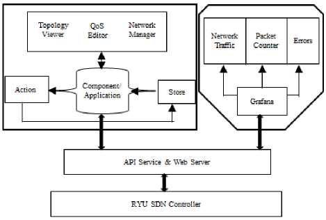
Fig.2. Block diagram of RYU web console
This front-end implementation is a web app developed to manage and control the network through a web-based interface consisting of various applications. The figure (Fig. 2) illustrates the architecture of the application and the interaction between all components.
Explanation of the implementation:
-
■ Web applications are developed to interact with the controller.
-
■ API and web server acts as a bridge between controller, network elements and web apps.
-
■ It consists of three main components:
-
- Topology viewer: It shows whole network topology as an interactive graph.
-
- QoS Editor: Allows administrators to add or remove QoS users and view QoS switches.
-
- Network manager: It shows all connected network elements like flows, port statistics of switches and allows administrators to add or remove flows as needed.
-
■ Grafana: Displays network traffic, packet flow and errors in a switch in the form of graphs [9].
-
4.2. Complete Implementation:
The implementation shows how all the components developed for separate purposes are combined to interact with each other, to offer various services and demonstrate an SDN.
The following figure (Fig. 3) illustrates the complete architecture of the implementation and an explanation subsequently.
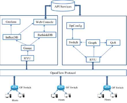
Fig.3. Complete Architecture of Our Implementation
Explanation of the implementation:
Two RYU SDN controllers (similar to Faucet [10]) are used in the implementation. One controller is for managing the network operations, and the other controller is for monitoring the network.
First controller : In this controller, there are four applications along with their dependencies.
-
■ Switch:
-
- It is the in-memory implementation of OpenFlow switch based on OpenFlow protocol 1.3.
-
- It is an extended version of RYU simple_switch_13 application.
-
- Its main job is to configure new switch, which enters the network and configure their multiple tables.
-
- Each switch has four tables:
-
■ Table 0: ACL table. This table has flow entries for access control, logging and firewall and load balancing.
-
■ Table 1: L2 Filtering table. This table has flow entries to separate traffic, redirect.
-
■ Table 2: Forwarding table. This table has forwarding rules for non-QoS uses.
-
■ Table 3: QoS table. This table has forwarding rules for QoS users.
-
- It handles forwarding of packets for normal users.
-
■ Graph:
-
- Build an in-memory graph of network elements in the network.
-
- It handles the discovery of switches, host links and ports.
-
- It calculates best effort path between a given source
and destination.
-
■ QoS(Quality of Service):
-
- It configures each switch as QoS switch
-
- It handles packet forwarding of prioritised/QoS users.
-
■ DpConfig: Maintains switch specific configurations [10].
Second controller : This controller monitors the network using following components:
-
■ Gauge [10] application:
-
- Polls statistics of each configured switch and puts it in the respective database.
-
■ Web Console:
-
- Provides interface to interact with a controller.
-
- Displays hosts, switches, and their details.
-
- Manage QoS users and network parameters.
-
■ Grafana: Data visualization & monitoring dashboard for network statistics [8].
-
■ RethinkDB and InfluxDB are NoSQL databases for storing user and network statistics respectively.
API Services: Provides APIs for interactions with OpenFlow switches.
-
V. Performance Evaluation
Ping is used for testing the reachability of a host on an Internet Protocol (IP) network. It measures the round-trip time for messages sent from the originating host to a destination computer that is echoed back to the source. A fast ping means a more responsive connection. Ping time may get affected due to various reasons including congestion in the network, the bandwidth of the network, and the load on the server. Lesser is the ping time; better is the network performance. Also, when a switch gets a packet with a new address, it sends the packet to the controller to define a path for the packet. The controller determines the path and makes an entry in the forwarding table of the switch for handling future packets with the same origin and destination. This process is called Packet-In. So, the performance of this implementation is checked by comparing Ping time and the number of packet-in of the developed implementation with the default implementation of the RYU SDN framework.
-
■ Linear topology
Table 1. Ping time and Packet-in Variation between Developed System and Default System in Linear Topology.
|
No. of Switches (Switches, hosts) |
The developed implementation |
Default implementation |
||||
|
Ping time |
Packet In (Ignoring ARP&ND) |
Ping time |
Packet In (Ignoring ARP&ND) |
|||
|
1st |
Other |
1st |
Other |
|||
|
2,2 |
30 ms |
0.046 ms |
2 |
30 ms |
0.42 ms |
4 |
|
2,3 |
33 ms |
0.066 ms |
2 |
30 ms |
0.42 ms |
6 |
|
3,3 |
44 ms |
0.062 ms |
2 |
58 ms |
0.43 ms |
10 |
|
4,4 |
382 ms |
0062 ms |
2 |
462 ms |
0.53 ms |
17 |
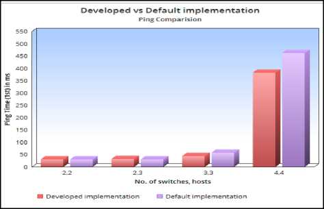
Fig.4. Ping Variation between Developed and Default Implementation in Linear Topology
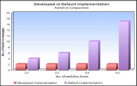
Fig.5. Packet-In Variation between Developed and Default Implementation in Linear Topology
-
■ Tree topology
Table 2. Ping time and Packet-in variation between Developed System and Default System in Tree Topology
|
No. of |
The developed implementation |
Default implementation |
||||
|
Ping time |
Packet In (Ignoring ARP&ND) |
Ping time |
Packet In (Ignoring ARP&ND) |
|||
|
Switches |
1st |
Other |
1st |
Other |
||
|
3 |
24 ms |
0.046 ms |
2 |
34 ms |
0.046 ms |
6 |
|
5 |
37 ms |
0.066 ms |
2 |
38 ms |
0.066 ms |
10 |
|
7 |
65 ms |
0.062 ms |
2 |
45 ms |
0.062 ms |
14 |
|
9 |
100 ms |
0.062 ms |
2 |
75 ms |
0.062 ms |
18 |
|
13 |
120 ms |
0.52 ms |
2 |
110 ms |
0.52 ms |
26 |
|
17 |
165 ms |
0.86 ms |
2 |
144 ms |
0.86 ms |
34 |
|
20 |
ISO ms |
0.115 ms |
2 |
200 ms |
0.115 ms |
40 |
|
30 |
300 ms |
0.2 ms |
2 |
330 ms |
0.2 ms |
60 |
|
50 |
800 ms |
0.3 ms |
2 |
880 ms |
0.3 ms |
100 |
|
too |
1750 ms |
0.45 ms |
4 |
4220 ms |
0.45 ms |
200 |

Fig.6. Ping Variation between Developed and Default Implementation in Tree Topology
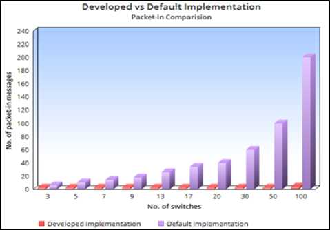
Fig.7. Packet-In Variation between Developed and Default Implementation in Tree Topology
Both the tests show that ping latency got reduced by 510% and 60-70% reduction in the number of packet-in in the solution developed, as the implementation calculates the best effort path from the origin of the packet completely through the network fabric to the destination and puts the appropriate flows in the switches.
-
VI. Quality of Service (QoS)
QoS implementation defines three Service Level Agreements (SLA) that enables transfer of the data according to the network performance, bandwidth, and the prioritisation of users to reserves network bandwidth and communicate with a constant communication bandwidth on the network. It is done by creating different pools of queues with required performance settings like defining a max rate and min rate of bandwidth. The network admin can associate an IP or group or network with any of the SLAs in real-time, and IP or group or network will adapt accordingly.
root@ubuntu:~# iperf -u -s -p 9875 -i 1
Server listening on UDP port 9875 Receiving 1470 byte datagrams UDP buffer size: 208 KByte (default)
|
15] |
local 10.0.0.2 port 9875 connected with 10.0.0.1 port 43919 |
||||||||
|
IB] |
Interval |
Transfer |
Bandwidth |
Jitter |
Lost/Total Datagrams |
||||
|
15] |
0,0- 1,0 |
sec |
115 KBytes |
941 Kbits/sec |
9,805 |
ms |
0/ |
80 |
(OK) |
|
15] |
1,0- 2,0 |
sec |
118 KBytes |
964 Kbits/sec |
8,404 |
ms |
0/ |
82 |
toa |
|
15] |
2,0- 3,0 |
sec |
119 KBytes |
976 Kbits/sec |
8,559 |
ms |
0/ |
83 |
toa |
|
15] |
3,0- 4,0 |
sec |
119 KBytes |
976 Kbits/sec |
6,416 |
ms |
0/ |
83 |
(oa |
|
15] |
4,0- 5,0 |
sec |
118 KBytes |
964 Kbits/sec |
6,192 |
ms |
0/ |
82 |
toa |
|
15] |
5,0- 6,0 |
sec |
119 KBytes |
976 Kbits/sec |
6,205 |
ms |
0/ |
83 |
toa |
|
15] |
6,0- 7,0 |
sec |
119 KBytes |
976 Kbits/sec |
6,129 |
ms |
0/ |
83 |
toa |
|
15] |
7.0- 8,0 |
sec |
118 KBytes |
964 Kbits/sec |
6,196 |
ms |
0/ |
82 |
toa |
|
15] |
8,0- 9,0 |
sec |
119 KBytes |
976 Kbits/sec |
6,385 |
ms |
0/ |
83 |
toa |
|
15] |
9,0-10,0 |
sec |
119 KBytes |
976 Kbits/sec |
6,230 |
ms |
0/ |
83 |
toa |
|
15] |
10,0-11.0 |
sec |
119 KBytes |
976 Kbits/sec |
6.078 |
ms |
0/ |
83 |
toa |
|
15] |
11,0-12.0 |
sec |
118 KBytes |
964 Kbits/sec |
6.374 |
ms |
0/ |
82 |
toa |
|
15] |
12.0-13.0 |
sec |
119 KBytes |
976 Kbits/sec |
6.031 |
ms |
0/ |
83 |
toa |
|
15] |
13.0-14.0 |
sec |
118 KBytes |
964 Kbits/sec |
6.361 |
ms |
0/ |
82 |
toa |
|
15] |
14.0-15.0 |
sec |
119 KBytes |
976 Kbits/sec |
6.087 |
ms |
0/ |
83 |
(oa |
|
15] |
15.0-16.0 |
sec |
119 KBytes |
976 Kbits/sec |
6.200 |
ms |
0/ |
83 |
toa |
Fig.8. UDP Traffic from 10.0.0.1 to 10.0.0.2 sent at 2Mbps. Bandwidth is shaped to ~1Mbps for Normal Users root@ubuntu:"# iperf -u -s -p 9875 -i 1
[ 15] local 10*0*0*2 port 9875 connected with 10*0*0*1 port 43878
Server listening on UDP port 9875 Receiving 1470 byte datagrams UDP buffer size: 208 KByte (default)
|
[ IB] |
Interval |
Transfer |
Bandwidth |
Jitter |
Lost/Total Bata1 |
|
[ 151 |
0.0- 1.0 |
sec 4.74 MBytes |
39.8 Mbits/sec |
0.014 ms |
0/ 3382 (0a |
|
[ 151 |
1.0- 2.0 |
sec 4.78 MBytes |
40.1 Mbits/sec |
0.022 ms |
0/ 3412 (О/) |
|
[ 151 |
2.0- 3.0 |
sec 4.77 MBytes |
40.1 Mbits/sec |
0.009 ms |
о/ 3406 toa |
|
[ 151 |
3.0- 4.0 |
sec 4.77 MBytes |
40.0 Mbits/sec |
0.025 ms |
0/ 3388 (Oa |
|
[ 15] |
4.0- 5.0 |
sec 4.77 MBytes |
40.0 Mbits/sec |
0.028 ms |
0/ 3403 (Oa |
|
[ 15] |
5.0- 6.0 |
sec 4.77 MBytes |
40.0 Mbits/sec |
0.039 ms |
0/ 3404 (Oa |
|
[ 15] |
6.0- 7.0 |
sec 4.77 MBytes |
40.0 Mbits/sec |
0.061 ms |
0/ 3402 (Oa |
|
[ 15] |
7.0- 8.0 |
sec 4.77 MBytes |
40.0 Mbits/sec |
0.058 ms |
0/ 3402 (Oa |
|
[ 15] |
8.0- 8.0 |
sec 4.77 MBytes |
40.0 Mbits/sec |
0.058 ms |
0/ 3402 (Oa |
|
[ 15] |
0.0-10.0 |
sec 47.7 MBytes |
40.0 Mbits/sec |
0.068 ms |
0/34011 (oa |
Fig.9. UDP Traffic from 10.0.0.1 to 10.0.0.2 sent at 5Mbps. Bandwidth is shaped to ~4Mbps for level 1 Users rootSubuntuT* iperf -u -s -p 9875 -i 1
Server listening on UDP port 9875 Receiving 1470 byte datagrams UDP buffer size: 208 KByte (default)
[ 15] local 10,0.0.2 port 9875 connected with 10.0,0.1 port 60911
|
[ IB] |
Interval |
Transfer |
Bandwidth |
Jitter |
Lost/Total Datagrams |
|
[ 15] |
0,0- 1.0 sec |
192 KBytes |
1,58 Mbits/sec |
8,246 ns |
0/ 134 (Oa |
|
[ 15] |
1.0* 2.0 sec |
187 KBytes |
1,53 Mbits/sec |
8.425 ms |
0/ 130 toa |
|
[ 15] |
2.0- 3.0 sec |
446 KBytes |
3,66 Mbits/sec |
4,564 ms |
о/ 3ii (oa |
|
[ 15] |
3.0- 4.0 sec |
461 KBytes |
3,77 Mbits/sec |
1.588 ms |
0/ 321 (oa |
|
[ 15] |
4.0- 5.0 sec |
459 KBytes |
3.76 Mbits/sec |
1.548 ms |
0/ 320 (oa |
|
[ 15] |
5.0- 6,0 sec |
462 KBytes |
3,79 Mbits/sec |
1,705 ms |
0/ 322 (oa |
|
[ 15] |
6,0- 7,0 sec |
464 KBytes |
3,80 Mbits/sec |
1,438 ms |
0/ 323 (oa |
Fig.10. UDP Traffic from 10.0.0.1 to 10.0.0.2 sent at 40Mbps. Level 2 will get Minimun 3Mbps and max all Available Bandwidth
SDN has generated its whole ecosystem since the inception of this idea. As evident in the paper, SDN is a way to configure the network using the software. SDN makes basic operations of a network like routeing, switching and network optimisations like load balancing and firewall a software challenge.
Normally a Network Management System will provide limited places to monitor the system. However, this limitation got broken because of our implementation. The administrator can monitor their network from anywhere in the scope of the network.
This implementation can help network administrators to monitor their network using various graphs and tables formed from the network statistics and control the network accordingly. They can get insights to the network state and take actions like adding or removing any network components as needed. It can also help administrators in providing differentiated quality of service to the users in the network.
The paper aimed at providing better control on the network for network administrators and a better experience for the users in the network.
The future scope of technology like SDN is great. Here in this implementation, though we could test the solution for any number of virtually simulated switches and hosts, we could not verify the solution in a larger physical network; we can check the solution for large physical networks of switches and hosts. Also, Network Functions
Virtualization solutions like load balancers and firewalls can be built to make the networks of future more robust, secure [11] and functional.
References A programmable and managed software defined network
- "Application of Software Defined Networks in Campus Network," [Online]. Available: http:/www.cse.iitd.ac.in/~cs5100295/reports/sdn.pdf. [Accessed 10 April 2017].
- "Operating expense," [Online]. Available: http://www.investopedia.com/terms/o/operating_expense.asp. [Accessed 10 April 2017].
- "Capital expenditure," [Online]. Available: http://www.investopedia.com/terms/c/capitalexpenditure.asp. [Accessed 10 April 2017].
- D. Kreutz and Fernando M. V. Ramos, "Software-Defined Networking: A Comprehensive Survey," Proceedings of the IEEE, pp. 11-17, Oct 2107.
- "Understanding the SDN Architecture," [Online].Available:https://www.sdxcentral.com/sdn/definitions/inside-sdn-architecture/. [Accessed 10 April 2017].
- H. Kim and N. Feamster, "Improving network management with software defined networking," IEEE Communications Magazine, vol. 51, no. 2, pp. 114-119, Feb 2013.
- "RYU," [Online]. Available: https://osrg.github.io/ryu/. [Accessed 10 April 2017].
- Rafaelhz, "react-material-admin-template," [Online].Available: https://github.com/rafaelhz/react-material-admin-template. [Accessed 21 Dec 2016].
- "Getting started with Grafana," [Online]. Available: http://docs.grafana.org/guides/getting_started/. [Accessed 2017 Feb 2017].
- "REANNZ/faucet," [Online]. Available: https://github.com/REANNZ/faucet.[Accessed 10 Feb 2017].
- Bassey Isong, Tebogo Kgogo, Francis Lugayizi,"Trust Establishment in SDN: Controller and Applications", International Journal of Computer Network and Information Security(IJCNIS), Vol.9, No.7, pp.20-28, 2017.DOI: 10.5815/ijcnis.2017.07.03
