A Quantitative Directional Relations Model Considering Topology and Distance

Author: Xuehua TANG
Journal: International Journal of Image, Graphics and Signal Processing(IJIGSP) @ijigsp
Article in issue: 2 vol.2, 2010.
Free access
Original models for direction relations ignored the restriction of topology and distance relations to direction representation. To improve the representation of direction relations model by pondering about the influence of topology and distance relations on direction relations, we categorize direction reference frame into topological reference and coarse directions reference and present a new direction relations quantitative and statistics models based on the new direction reference frames. Instead of degree, this new model uses a coordinate-based quantitative method to describe direction relations for the distance restrain, while it reflects the constraints of topology by the direction reference frame and by the coordinate representation. It covers all intricacies imposed by different types of objects and has more sensitivity to the configuration of objects. Experiments have been carried out and the results indicate the excellent efficiency in view of directional description.
Directional relations, coarse direction relations reference, directional topologic reference, directional coordinate
Short address: https://sciup.org/15012035
IDR: 15012035
Text of the scientific article A Quantitative Directional Relations Model Considering Topology and Distance
Published Online December 2010 in MECS
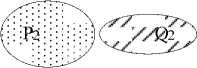
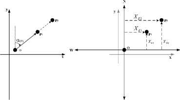
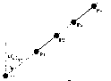
There are three main categories of spatial relations in geographic applications, including directions [1-8], topological relations [11-13] that describe concepts of neighborhood and incidence [18], and distances [20-21]. Three types of spatial relations are not isolated and restrained each other. The topological and distance relations are essential complement to the formalisms of direction relations. Topological relations affect it in the aspect of the reference frames. For example, as showed in Fig. 1, the directional relation between Q1 and P1 is different from the directional relation between Q2 and P2 for the difference in the topology. Directional reference frames is affected by the topological relations between two objects and the spatial cognizance custom. In the original models, these direction reference frames focused on the definition of coarse directions and ignored the affection of topologic relations. And distance relations can improve the precision of the directional relations model. As showed in Fig. 2, P2 lies in east of P1, while the representation result of directional relation based on the original degree-based quantitative model could not distinguish the directions of P1 and P2 to Q. The basic reason is that old degree-based model ignored the constraint of distance relations to the directional relations.
(a)
Figure 1.
(b)
Effect of topology
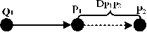
Figure 2. Effect of distance
This paper focuses on the influence of topology and distance relations on the formalisms of direction relations. A novel quantitative approach is pursued to model direction relationship with the restriction to topological and distance relations. Topological reference frame is introduced into the direction reference frames to formalism the influence of topological relations on directional relations models. Based on the new directional reference frames, a coordinated-based directional relations model is defined.
The remainder of this paper is organized as follows. Section 2 motivates a new directional reference frame, which introduces the direction topological reference based on the topologic partition. Section 3 proposes a quantitative coordinate-based model of direction relations. Section 4 shows the experiments results of the models. Section 5 presents the conclusions.
-
II. Direction Reference Frames
Direction is an ordered relation between reference object and target object. The direction is defined by the direction reference frames after the reference and target objects are selected. Original direction reference frames focused on the definition of coarse directions and ignored the influence of topological relations on the direction reference. In order to build the restriction of topological to direction reference, this paper partitions the direction reference frames into topologic direction reference and coarse directions reference. The topologic direction reference defines the impact of the topologic relation between reference and target objects to the direction relationship. The cardinal direction reference refines the selection of cardinal directions.
A. Topologic Direction Reference
Based on the partition of the topologic space, we define three types of topological direction reference to deal with the definitions of direction relations in the cases of different topologic relations.
If the points lie in the exterior space of reference object, Considered the reference object as a whole, we select the center of reference object’s MBR as the origin of direction relation, denoted by O, regarding the reference object as a whole. It is called exterior direction reference.
When the target object is in the scope of the interior or boundary of reference object, in term of the description habit, the reference center should be inside it. We call this center interior center, denoted by C. For line and region reference objects, C is the abstraction of them and should reflect the characters of shape and distribution of them. C has to fulfill two rules: 1) it must be inside the object; 2) it should be the center of reference object and reflect the shape and distribution of reference object.
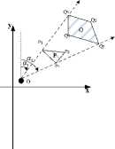
For line reference object, the length of line is the invariant of distribution. So we define C by the midpoint of reference line. In term of the invariant of distribution to a region, centroid is commonly used to be center of a region. If the region is a concave polygon, its centroid lies outside the region and obey the first rule. So we introduce an approach based on the skeleton center of region (CHEN Tao etc., 2004). The flow chart for interior center algorithm is showed as Fig.3. The triangulations are formed by the constraint Delaunay triangulation and are divided into three types by the different topology conditions. The first type of triangulation has one vertex which is the node of the skeleton. The second type has two adjacent Delaunay triangulations and the third type is the intersection of the three branches of skeleton. Then convex degree and minimum variance are defined as the parameters of computing. The definition of convex degree is:
ф = Area(Polygon)/Area(Convex) (1)
If Ail,Ai2 and Ai3 are the areas of three regions divided by the edges of the third type of triangulation, and the whole area of region A = Ail+Ai2+Ai3 , minimum variance, denoted by 6min, is defined as follow: 5 = 2 [(A il - A/3)2 + (A i2 — A/3)2 + (A il — A/3)2] (2)
5m in = min (5 2 ,5 2 ,^, 5 П ) (3)
Above all, reference point has only exterior referenc e. The exterior origin of reference line or region is the cen ter of their MBR. Interior and boundary origin of referenc e line is the midpoint of it. And interior and boundary ori gin of reference region is interior center of it.
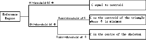
Figure 3. Flow of the interior center computation
B. Cardinal Direction Reference Frames
Cardinal direction reference assigns direction symbols to direction partitions of space. Based on the traditional models, cardinal direction reference frames include relative (front, back, left, and right) and extrinsic (north, west, east, and south) reference frames. This paper uses an extrinsic reference frame and retains the four cardinal directions, which are north, west, east and south.
-
III. Directional relations coordinate model
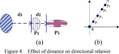
A. Effect of distance on directional relation
The distance between spatial objects affects the directional relations [11]. For example, there are two regions in two-dimensional space (showed in Fig. 4a). It is clearly that P 1 and P 2 are east of R. The difference between P1 and P2 is caused by the distance between them. The other typical example is showed in Fig.4b. The direction relations of several points in the same ray line are different because of the different distances.
Mathematically, polar coordinates represent the location with the angle and distance. Traditional anglebased directional relations models are not complete in representation of location in two-dimensional space [10]. Project-based directional relations models can reflect the difference of directional relations caused by distance to a certain extent but do not formalize the effect of the distance.
B. Definition of directional coordinates
Direction is a binary function that maps two points (P1, P2) in the plane onto a symbolic direction Cardinal directions depend on the direction of travel [1]. It is known that the direction relation between two points can be defined accurately. To represent directional relations of various kinds of objects, we propose a model of directional relation between two points.
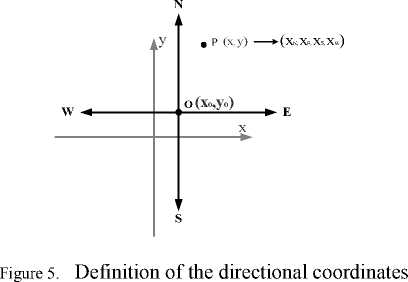
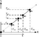
Direction is a binary function that maps two points (P1, P2) in the plane onto a symbolic direction d. The specific directional symbols available depend on the system of directions used, e.g., D4 = {N, E, S, W} or more extensive D8 = {N, NE, E, SE, S, SW, W, NW} [1]. Cartesian coordinate has the completeness in the location in two-dimension space. Comparing the cardinal direction to the Cartesian coordinate, it is clearly accordant as the direction of N and S correspond to the Y axis and the direction of E and W correspond to the X axis. The cardinal directions just divide the coordinate axis of the Cartesian coordinate into two opposite directions. So the reference system of D4 is complete and reasonable. As showed in Fig.5, We define the directional coordinates (xN, xE, xs, xW) based on the D4 reference system as follows:
Definition! If the coordinate of origin point is (x1,y1), and the coordinate of origin point is (x2,y2), directional coordinates (xN, xE, xs, xW) is defined as:
У 2 - У 1 < 0 ^ xn = У 2 - У 1 ;x s = 0
У 2 - У 1 > 0 ^ xn = 0; x s = У 2 - У 1
x2 - xi < 0 ^ xE = x2 - xi;xW = 0
x2 - xi > 0 ^ xE = 0; xW = x2 - xi
У 2 — У 1 = 0 ^ xn = x s = 0
x2 - xi = 0 ^ xE = xW = 0
The directional coordinates can distinguish the different directional relation of the points in the same ray line. The characters of this model are discussed by three theorems.
Theorem1 . If the directional coordinate in a certain direction (such as north) of a primary point is larger than another point, it can conclude that this point is the certain direction (such as north) to another point.
This character ensures that ability to distinguish the different points in the same ray line.
Theorem2 . If the directional coordinates from point P1 to the point P2 is dir(Pi,P2) = (xN, xE, xs, xW) , then the directional coordinates from point P2 to the point P1 is:
dir(P 2 ,P i ) = inv(dir(P i ,P 2 )) = (x n' , xE', x s ', x w ') : x n' = x s ,x E = x w ,x s = x n ,x W = xE.
Theorem3 .If the directional coordinates from point P1 to the point P2 is (xN, xE, xs, xW) and the directional coordinates from point P2 to the point P3 is (xN ' , xE', xs', xW') , the directional coordinates from point P1 to the point P3 is (xN '' , xE '' , xs '' , xW '' ) : xN '' = xN + xn' , xe'' = xe + xe' , xs'' = x s + xs' , xw'' = xw + xw' .
The characters of directional coordinate model illustrate the superiority of the new model. In the next section, the computation of the directional coordinates for various types of spatial objects (point, line and area) is to be discussed.
C. Point as reference object
-
1) point-line
The topologic relations between a point and a line may be disjoint or contained. When the point O and the polyline LP 1P2 Pn is disjoint, their directional coordinate is:
dir(o,LE i pn ) = [dir(O,P i ),dir(O,P 2 ),™,dir(O,Pn)]
= [(xNi, xEi, xsr xW1),(xN2, xE2, xs2, xW2), .,(xNn, xEn, xsn, xWn)]
If the reference point is the node of the target line, the coordinate of the node is (0, 0, 0, 0) . The directional coordinate is:
dir(O,Lp1„pn) = [dir(O, Pi),dir(O, P2)] = [(0, 0, 0, 0),(xn2, xe2, xs2, xw2), ...,(xN2n, xEn, xsn, xwn)](4)
When the reference point is in the interval of vertice i and vertice (i+1), the directional coordinate is:
[dir(O, Pi),., dir(O, Pj),O, dir(O, Pi+i),.,dir(O, Pn)]
-
2) point-region
Point-region is similar to point-polyline. For example, Eqs. 3 can be extended as follows:
dir(O, R p1p2 _ pn ) = [dir(O, P i ),dir(O, P 2 ),., dir(O, PJ] (6)
Line as reference object
-
3) line-point
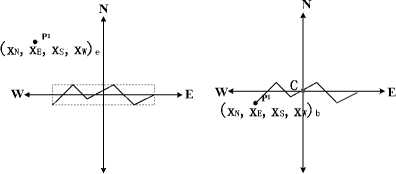
The topological relations between a reference line and a target point may be disjoint, adjacent and contain. If target point is disjoint to reference line, as shown as Fig.6a, the exterior direction coordinate is:
-
4) line-line
The topological relations between a reference line and a target line may be disjoint, adjacent, contain, and contained.
= [dir(O, P i ),dir(O, P 2 ),., dir(O, P n )]
[(x Ni , x Ei , x si , x Wi ) e ,(x N2 , x E2 , x s2 , x W2 )e,. ,(x Nn , x En , x sn , x Wn ) e ] (10)
If the target line completely contains the reference line, the superposition of two lines is denoted by ‘O’, and the other parts use the exterior reference. When the target line is completely contained by the reference line, the direction coordinates are computed by interior reference.
In Fig.7a, the reference line contains a part of the target line. The target line should be divided into two parts: interior and exterior. The interior points’ coordinates are computed upon the interior reference and the exterior points based on the exterior reference.
s
(b)
s
(a)
Figure 6. direction coordinates of line-point
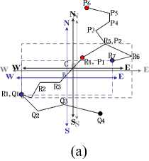
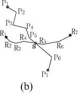
Figure 7. directional coordinates of line-line
Therefore, the directional coordinate between LR 1R2_R7 and lp1p2^p6 is:
dirO- IM^.R 'Lr i^.l’. ) = {[dir(C,P i ) i ,dir(C,P 2 ) i ] U (dir(O, P2)e,dir(O, P3)e U dir(O, P4)e U dir(O, P5)e U dir(O,P6) e ]} (11)
With the case of target line adjacent to reference line in the interior part, the adjacent part is defined upon the interior reference and the other parts are upon exterior reference. For example, as shown in Fig.7b, the directional coordinate between LR 1R2_R7 and Lq1q2q3q4 is:
dirO'IM^.-R -LQiQ.^-Q J =
{dir(B,Q i )b U
(dir(O, Q i )e,dir(O, Q 2 )e,dir(O, Q3) e ,dir(O, Q 4 ) e ]} (12)
When the target line intersects the reference line, as shown in Fig.b, the intersection partitions the target line into two exterior parts. To yield a consistent directional coordinates, we compute the exterior and interior coordinates of intersection. If the intersection in the interval of the i point and the (i+1) point of reference line, the directional coordinate between L and L is:
{[dir(O, Pi)e,dir(O, p2)e,™, dir(O, P1)e,dir(O, S)e) U dir(C,S)i U (dir(O,S)e,dir(O,Pi+i)e,™,dir(O,Pn)e]} (13)
-
5) line-region
For the case that target object is a region, the computation of directional relations is similar to the case with target object being a polyline.
Region as reference object
-
6) region-point
When the target point lies in the exterior of reference region, the exterior directional coordinate is:
dir(R,P) = dir(O,P)e = (xnp, Xep, Xsp, XwP)e
If target point lied in the boundary of reference region, the boundary directional coordinate is:
dir(R,P) = dir(C,P)b = (xnp, Xep, Xsp, XwP)b
Based on the interior reference point, the interior directional coordinate is:
dir(R,P) = dir(C,P)i = (xNp, Xep, Xsp, XwP)i
-
7) region-line
The case with a reference region and a target line can be analyzed by using a similar approach to that for the case with a reference line and a target line. The coordinate between disjoint reference region and target line is:
dir(R, L pip2_pm ) = dir(O, L pip2_pm ) e =
[dir(O,P i ) e ,™,dlr(O,Pm) e ] (17)
With the case of target line adjacent to reference region in the interval [Pi,P j ], Eqs. 11 is extended to:
dir(R, L PiP2_Pm ) = dir(O,L pip2_p . )eU dir^C, L p . _p . ^bU dir(O,L pj„P m )e (18)
With the case of reference region intersecting target line, Eqs. 12 is extended to:
dir(R,LP1P2^Pm) = [(dir(O,LP1^Pi)e U dir(C,Pi)b U dir (C, LPi^Pj)i U dir(C, Pj)b U (dir (O, LPj^Pm)e]
-
8) region-region
Region-region is similar to region-line.
-
IV. Analytical performance evaluation
The main experiment is to evaluate the sensibility of this model to the spatial correlative factors by comparing to angle-based model. The principal factors, which are correlative to the direction, include distance, shape and size.
The factor of distance
The distance between spatial objects affects the directional relations [2]. As showed in the Figure8, the experimental data is a group of spatial objects in same size and shape. But their distance to the reference object is different. As showed in Figure8, we use the coordinatebased model and angle-based model to compute the directional relation respectively. Comparing Fig.8a and Fig.8b it can be seen that the angle-based model get the same result in the cases of different points, and the result of coordinate-based model is completely different. The same thing happens to the case of line to line, as shown in Fig.8c and Fig. 8d.
(a) (b)
X
X
X
X
|
Exterior origin : (384.5,693.75) Interior origin: (271.3,654.9) Intersection: (458.8,465.1) |
Degree-based model: no representation |
T able II. example of line - point directional coordinates
(c)
Figure 8. Effect of distance on direction relations
(a)
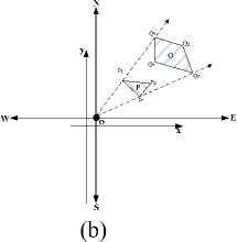
Figure 9. Effect of shape on direction relations
The factor of size and shape
The size and shape are the crux of representation of direction relations. We choose two areas, which are in the same range of angle, to be the experimental data. As showed in Fig.9b, coordinate-based model can distinguish the direction relations between two areas, while angle-based model get the same results, as shown in Fig.9a.
The computation of directional coordinate
T able I. example of line - region directional coordinates
|
Disjoint |
R i (212.3,1015/ R 2 (457.6,654.9) R3 (167.3,654.9) R 4 (601.7,372.1) |
P i (573.6,1123.7) P 2 (1053.7,513.2) Р з (1231.9,851.1) P 4 (1017.2,1123.7 P5(917.3,872.3) |
Exterior origin : (384.5,693.75) |
Directional coordinates : [(430.0,189.1,0.0,0.0)e (0.0,669.2,180.5,0.0) e , (157.4,847.4,0.0,0.0) e , (430.0,632.7,0.0,0.0) e , (178.5,532.8,0.0,0.0)e ] |
|
Degree-based model: [307.4 ° , 360.0 ° ] U [0°,40.0°] |
||||
|
Adjacen t |
R i (212.3,1015/ R2(457.6,654.9) R 3 (167.3,654.9) R 4 (601.7,372.1) |
3i (212.3,1015.4) P 2 (692.4,404.9) Р з (870.6,742.8) > 4 (655.9,1015.4) P 5 (556.0,764.0) |
_____L_ ......-^' Exterior origin : (384.5,693.75) Boundary origin : (271.3,654.9) |
Directional coordinates : (360.5,0.0,0.0,59.0)b U ((321.6,0.0,0.0,172.2) , (0.0,307.9,288.9,0.0)e, (49.0,486.1,0.0,0.0) e , (321.6,271.4,0.0,0.0) e , (70.3,171.5,0.0,0.0)e] |
|
Degree-based model: no representation |
||||
|
Interse ct |
R i (212.3,1015/ R2(457.6,654.9) R 3 (167.3,654.9) R 4 (601.7,372.1) |
P i (373.9,573.1) P 2 (854.0,-37.4) Р з (1023.2,300.5) P 4 (817.5,573.1) P 5 (717.6,-321.7 |
Directional coordinates : [(0.0,0.0,120.6,10.6) e , (0.0,469.5,731.1,0.0) e , (0.0,638.7,393.3,0.0) e , (0.0,433.0,120.6,0.0) e , (0.0,333.1,1015.5,0.0) . U [(0.0,187.5,189.8,0.0 (0.0,330.4,282.8,0.0) 1 ) U (0.0,330.4,282.8,0.0) b |
|
Disjoint |
R i (235.5,189.1 R 2 (309.7,200.3 R 3 (359.1,156.5 R 4 (313.0,126.2 R 5 (371.5,76.8) R6(308.6,46.5) R7 (254.5,66.7) R8(233.2,111.6 R g (233.2,189.1 |
P i (387.2,217.2) P 2 (465.9,223.9) Р з (504.1,185.7) P 4 (486.2,143.1) P 5 (450.2,164.4) Р б (415.3,145.3) |
Exterior origin : (302.4,123.4) |
Directional coordinates : [(93.8,84.8,0.0,0.0) e , (100.5,163.5,0.0,0.0)( (62.3,201.7,0.0,0.0) e , (19.7,183.8,0.0,0.0) e , (41.0,147.8,0.0,0.0) e , (21.9,112.9,0.0,0.0)e] Degree-based model: [73.6°,127.5°] |
|
Adjacent |
R i (235.5,189.1 R 2 (309.7,200.3 R 3 (359.1,156.5 R 4 (313.0,126.2 R 5 (371.5,76.8) R 6 (308.6,46.5) R 7 (254.5,66.7) R 8 (233.2,111.6 R g (233.2,189.1 |
P i (341.2,61.1) P 2 (419.8,67.8) Р з (458.1,29.6) P 4 (440.1,-13.0 P 5 (404.1,8.3) Р б (369.2,-10.8 |
Exterior origin : (302.4,123.4) Boundary origin : (328.8,76.5) |
Directional coordinates : (0.0,12.4,15.4,0.0) b U ((0.0,38.8,62.3,0.0) (0.0,117.4,55.6,0.0) e , (0.0,155.7,93.8,0.0) e , (0.0,137.7,136.4,0.0) . (0.0,101.7,115.1,0.0)e (0.0,66.8,134.2,0.0)e] Degree-based model: no representation |
|
Interse ct |
R i (235.5,189.1 R 2 (309.7,200.3 R 3 (359.1,156.5 R 4 (313.0,126.2 R 5 (371.5,76.8) R 6 (308.6,46.5) R 7 (254.5,66.7) R 8 (233.2,111.6 R g (233.2,189.1 |
P i (311.9,183.5) P 2 (390.6,190.2) Р з (428.8,152.0) P 4 (410.8,109.4) P 5 (374.9,130.7) Р б (340.0,111.6) P 7 (311.9,183.5) |
> . p ь Exterior origin : (302.4,123.4) Boundary origin : (328.8,76.5) Interior origin : (328.8,76.5) Upside intersection : (327.2,184.8) Underside intersection : (329.9,137.3) |
Directional coordinates : [(107.0,0.0,0.0,16.9) (108.3,0.0,0.0,1.6) 1 , (80.0,30.3,0.0,0.0) 1 , (60.8,1.1,0.0,0.0) i ] U [(108.3,0.0,0.0,1.6) (80.0,30.3,0.0,0.0) b , (60.8,1.1,0.0,0.0) b ] U [(61.4,24.8,0.0,0.0) (66.8,88.2,0.0,0.0) e , (28.6,126.4,0.0,0.0) e , (0.0,108.4,14.0,0.0) e , (7.3,72.5,0.0,0.0) e , (0.0,37.6,11.8,0.0) e , (13.9,27.5,0.0,0.0) e , (33.1,56.7,0.0,0.0)e] Degree-based model: no representation |
|
Containe d |
R i (235.5,189.1 R 2 (309.7,200.3 R 3 (359.1,156.5 R 4 (313.0,126.2 R 5 (371.5,76.8) R 6 (308.6,46.5) R 7 (254.5,66.7) R 8 (233.2,111.6 R g (233.2,189.1 |
P i (272.6,178.6) P 2 (296.0,179.9) P 3 (314.9,159.9) P 4 (297.6,134.9) P 5 (304.5,99.2) P 6 (274.8,123.7) P 7 (280.7,143.8) |
R2 R- _ RS Interior origin : (328.8,76.5) |
Directional coordinates : [(102.1,0.0,0.0,56.2) (103.4,0.0,0.0,32.8) 1 , (83.4,0.0,0.0,13.9) 1 , (58.4,0.0,0.0,31.2) 1 , (22.7,0.0,0.0,24.3) 1 , (47.2,0.0,0.0, 54.0) 1 , (67.3,0.0,0.0,48.1) 1 ] Degree-based model: no representation |
The experiment of computation chose the line-region and region-region. As showed in Tab.1 and Tab.2, the new model can represent the directional relations in more topologic relations than degree-based model.
V. conclusion
This paper presented a new quantitative coordinatebased direction relations model which concentrates on the quantitative representation of direction relation in the case of objects in the same ray line, and the effect of distance, size and shape on describing direction relations. It has the mathematic completeness and improves results of directional representation.
Based on the basic definition of directional coordinates, directional relations model for different types of spatial objects were discussed. The results of analysis proved the new model can give more expressive power and reduces the amount of computation. Comparing with angle-based direction relations model , the cardinal advantages of this model are in four aspects:
-
1) This model is more accurate in the representation of direction relations as the mathematical completeness in the description of spatial reasoning.
-
2) The model can distinguish the direction relations between the objects in the same ray.
-
3) The model can be more efficient because of the simple computation.
-
4) The model is more sensitive to the factors of location, distance, size and shape.
Acknowledgment
This work was supported in part by a grant from the Fundamental Research Funds for the Central Universities (213275857).
References A Quantitative Directional Relations Model Considering Topology and Distance
- A. Frank. “Qualitative Spatial Reasoning: Cardinal Directions as an Example”, International Journal of Geographic Information Systems, 1996, 10 (3): 269 -290.
- D. Peuquet, C.X. Zhan, “An algorithm to determine the directional relationship between arbitrary-shape polygons in the plane”, Pattern Recognition, 1987, 20(1):65–74.
- A. Frank. “Qualitative spatial reasoning about distances and directions in geographic space”, Journal of Visual Language and Computing, 1992, 3:343–371.
- DENG Min, “Discussion on Statistical Model of Direction Relation Between Spatial Objects in GIS”, Geoinformatica, 2008,12:193–217.
- XIA Yu, ZHU Xinyan, LI Deren, QIN Kun,. Research on spatial directional relation description model, Science of Surveying and Mapping, 2007, 32(5), pp.94-97.
- Yan H W, “Research on Formal Description Model of Spatial Direction”, Acta Geodaetica et Cartographica Sinica,2003, 32(1):42-46
- J.F. Allen, “Maintaining knowledge about temporal intervals,” Communications of the ACM, 1983, Vol. 26(11):832–843.
- R. Billen, E. Clementini, “Introducing a reasoning system based on ternary projective relations in P.Fisher(Ed.)”, Developments in Spatial Data Handling, 2004,381–394.
- B. Bennett, “Logical representations for automated reasoning about spatial relations” , Ph.D thesis, School of Computer Studies, University of Leeds, 1997.
- S.K. Chang, Q.S. Shi, and C.W. Yan, “Iconic indexing by 2D-strings,” IEEE Transactions on Pattern.
- S.K. Chang and E. Jungert, Symbolic projection for image information retrieval and spatial reasoning, London: Academic, 1996.
- J. Chen, C. Li, Z. Li, and C. Gold, “A Voronoi-based 9-intersection model for spatial relations”, International Journal of Geographical Information Science, 2001, 15(3):201–220.
- S. Cicerone, P. Di Felice, “Cardinal directions between spatial objects: the pairwise-consistency problem”, Information Sciences, 2004, 164:165–188.
- C. Claramunt, M. Thériault, “Fuzzy semantics for directional relations between composite regions”, Information Sciences, 2004, 160:73–90.
- E. Clementini, P. Di Felice, and D. Hernández, “Qualitative representation of positional information”, Artificial Intelligence, 1997, 95(2):317–356.
- M. Egenhofer and R. Franzosa,. “Point-set topological spatial relationships,” International Journal of Geographical Information Systems, 1991, 5(2):161–174.
- R. Goyal, “Similarity assessment for cardinal directions between extended spatial objects”, Ph.D thesis, University of Maine, 2000.
- R. Haar, “Computational models of spatial relations”, Technical report: TR-478, MSC-72-03610, Computer Science, University of Maryland, 1976.
- D. Hernández, “Qualitative representation of spatial knowledge”, Lecture Notes in Computer Science, 804, Springer, 1994.
- Z.L. Li, R.L. Zhao, and J. Chen,. “A Voronoi-based spatial algebra for spatial relations”, Progress in Natural Science, 2002, 12(7):528–536.
- G. Ligozat, “Reasoning about cardinal directions,” Journal of Visual Languages and Computing, 1998, 9:23–44.
- A. Mukerjee and G.A. Joe. “Qualitative model for space”, Proceedings of the 8th National Conferenceon Artificial Intelligence, Boston, MA, 1990, pp.721–727.
- D. Papadias, “Relation-based representation of spatial knowledge,” Ph.D thesis, Department of Electricaland Computer Engineering, National Technical University of Athens, 1994.
- D. Papadias and M. Egenhofer. “Algorithms for hierarchical spatial reasoning,” GeoInformatica, 1997, 1(3):251–273.
- D. Pullar and M. Egenhofer, “Toward formal definitions of topological relations among spatial objects”, Proceedings of the 3rd International Symposium on Spatial Data Handling, Sydney, Australia, August, 1988.
- D.A. Randell, Z. Cui, and A. Cohn, “A spatial logic based on regions and connection”, Proceedings of the 3rd International Conference on Knowledge Representation and Reasoning, Morgan Kaufmann, San Mateo, CA, 1992, pp. 165–176.
- J. Renz and B. Nebe, “On the complexity of qualitative spatial reasoning: A maximal tractable fragmentof the region connection calculus”, Artificial Intelligence, 1999, 108(1–2):69–123.
- R. Röhrig, “A theory for qualitative spatial reasoning based on order relations”, Proceedings of the 12th International Conference on Artificial Intelligence, 2: 1418–1423, 1994.
- J. Sharma. “Integrated spatial reasoning in geographic information systems: Combining topology and direction,” Ph.D thesis, The Graduate School, University of Maine, 1996.
- A.P. Sistla, C. Yu, and R. Haddad. “Reasoning about spatial relationships in picture retrieval systems,” in Proceedings of VLDB-94, 570–581, 1994.
- S. Skiadopoulos and M. Koubarakis, “Composing cardinal directions relations”, Proceedings of the 7th International Symposium on Spatial and Temporal Databases (SSTD’01), Springer, Berlin, 2001,299–317.
- R.K. Goyal, “Similarity Assessment for Cardinal Directions Between Extended Spatial Objects”, Ph.D Thesis, the University of Maine, 2000.
- LIU Yu, GONG Yongxi, ZHANG Jing and GAO Yong, “Representation and Reasoning of Spatial Relations in Geographical Space”, Geography and Geo-Information Science, 2007, 23(5), pp.1-6.
- Yan H., Chu Y., Li Z and Guo R., “A quantitative description model for direction relations based on direction groups”, Geoinformatica, 2006, 10(2), pp. 177- 195.
- Spiros Skiadopoulos, Nikos Sarkas, Timos Sellis and Manolis Koubarakis, “A Family of Directional Relation Models for Extended Objects”, IEEE TRANSACTIONS ON KNOWLEDGE AND DATA ENGINEERING, 2007.19(8), pp.1116-1129.
- Chang S K, etc. “Iconic Indexing by 2-D string”, IEEE Trans. Pattern Anal•Machine Intell•, 1987,(9) : 413-428.
- R.K. Goyal, Max J. Egenhofer, “Similarity of Cardinal Directions”, Proceedings of ACM SIGMOD International Conference on Management of Data, 1984, 8: 47-57.
