A technique for determining the acoustic characteristics of combustion chambers of a solid propellant rocket engine

Author: Astakhov S. A., Biryukov V. I., Sizov G. A.
Journal: Siberian Aerospace Journal @vestnik-sibsau-en
Section: Aviation and spacecraft engineering
Article in issue: 2 vol.22, 2021.
Free access
Many developers of new high-thrust solid-propellant rocket engines are faced with the problem of acoustic instability of combustion. The phenomenon of resonant combustion of solid fuel is associated with a number of specific features. The cavities of the combustion chambers of such engines have complex geo-metric shapes. The gas channel is long enough. Its length usually exceeds five or more calibers. The thick-ness of the flame front is measured in micrometers and the combustion zone is localized over the open fuel surface. The flame front often turns out to be capable of amplifying pressure perturbations at the frequency of one of the acoustic eigenmodes if the wave antinode falls on a thin combustion zone. The oscillatory process can be regular or sporadic. Resonances of the longitudinal acoustic mode are most often observed. However, there were cases of simultaneous oscillation of two modes. In some cases, during the operation of the engine, the amplitude of the resulting oscillations began to decrease and the combustion process be-came almost quasi-stationary. Self-oscillatory processes in the combustion chambers of solid propellants have a threshold sensitivity to pressure overshoots. The vibration amplitudes can be several tens of percent, sometimes reaching the nominal working pressure in the chamber. The amplitude-frequency characteristics of the oscillations are sensitive to the composition of the fuel, responding to changes in the chemical com-position, as well as to the mechanical properties of the fuel. The regions of unstable regimes are definitely related to the geometry of the gas cavity. Together with pressure fluctuations, the combustion process is influenced by gas-dynamic factors, significant non-uniformity of the gas flow parameters along the length of the channel, its turbulence, and other factors. When designing solid-propellant rocket engines, it is nec-essary to estimate the frequencies of the natural acoustic resonances of the combustion chambers. The article discusses a technique for determining the frequencies of natural resonances of the first and second tone of the longitudinal mode of acoustic vibrations in the combustion chambers of solid propellant rocket engines. The gas path of the combustion chamber is divided into homogeneous sections, for which the solutions of the wave equation are presented. To determine the natural frequencies and distribution of vibrational pressures and velocities, the method of “stitching” acoustic fields at the boundaries of the cavi-ties was used.
Acoustic vibrations, longitudinal mode, frequency, damping decrement, wavenumber, quality factor.
Short address: https://sciup.org/148321806
IDR: 148321806 | UDC: 628.7.036.54 – 662.61 | DOI: 10.31772/2712-8970-2021-22-2-302-315
Text of the scientific article A technique for determining the acoustic characteristics of combustion chambers of a solid propellant rocket engine
The problem of acoustic instability of combustion in solid-propellant rocket engines is no less urgent in comparison with high-thrust liquid-propellant rocket engines [1–4]. As a rule, the acoustic cavity has a complex geometric shape. The combustion zone is located in close proximity to the interface between the phases – a solid charge and a gas path. The thickness of the combustion zone of the mixed composition at a pressure of up to 4 MPa and a gas temperature of the order of (2500–3000) K is approximately 70–90 microns. A thin combustion zone often turns out to be capable of amplifying the pressure disturbances of the acoustic mode for which the maximum wave falls on the combustion surface. The effect of acoustic pressure fluctuations on the combustion process, in accordance with the Rayleigh criterion, causes fluctuations in the combustion rate [2–12]. The presence of this feedback leads to an increase in pressure fluctuations in a thin zone of chemical reactions with high temperature gradients, fuel vapor concentration, and high rates of energy and mass transfer. In addition, the possible thermodynamic heating of the gas during its compression should be noted. In some cases, fluctuations in acoustic velocity can also play an important role. When solid fuels are burned, turbulent pulsations are present in the channels of the checker – combustion noises. They are due to different excitation mechanisms and have a different physical nature. Sound noise is usually associated with gasdynamic reasons of the same nature as in turbulent gas flows. In combustion chambers, regular pressure fluctuations with a frequency close to the natural (acoustic) frequency of the gas column oscillations [7–12] can increase, and more often stabilize at a certain level due to acoustic losses. The acoustic instability of combustion is an autowave process with feedback through the action of sound waves on combustion. The parameters of the wave process: frequency, amplitude and form of oscillations are determined by the properties of the solid-propellant rocket engine charge as a dynamic system. Sound noise in the chamber cavity can also be considered as a self-oscillatory process [6], in which the energy source is heat release during combustion, and feedback arises due to the effect of sound waves on combustion, while persistent pulsations of a stochastic nature arise [11], which have a wide frequency band and random phases. However, the frequency response of the acoustic cavity often has frequency selectivity characterized by a high Q factor with respect to the longitudinal mode [2–4].
Most theoretical works analyze the effect of small perturbations on the stability of combustion. However, given the complex nonlinear mechanism of solid fuel transformation into the gas phase (heating, pyrolysis, sublimation, etc.), the combustion process and its interaction with gas-dynamic phenomena in the acoustic path of solid-propellant rocket engines are often characterized by “hard” excitation of self-oscillations. Otherwise, the dynamic system can become unstable when the amplitude of the disturbances increases above a certain threshold limit. Disturbances with an amplitude below the threshold attenuate. Rigid excitation of oscillations is characteristic of nonlinear dynamic systems. The development of nonlinear theories is greatly complicated by mathematical difficulties. Linear theories can be quite useful for understanding instability and, in some cases, for nonlinear applications.
An assessment of the stability of combustion in solid-propellant rocket engines can be carried out on the basis of determining the balance of acoustic energy in the combustion chamber, taking into account the influx of acoustic energy (due to the interaction of acoustic vibrations with the combustion process) and losses of acoustic energy during the period of vibrations. The diagnostic indicator of the margin of linear stability of the combustion process is the coefficient (decrement) of damping of oscillations [2; 7–12]. The attenuation coefficient has a certain physical meaning:
δ= E 2 - E 1
ν 2EСУМ , where Е2 is the inflow of acoustic energy generated by the oscillating system during the vibration period; Е1 is a part of the energy dissipated by the oscillatory system during the vibration period; ЕСУМ – acoustic energy stored by the system during the vibration period.
The influx of acoustic energy from the combustion process depends – at certain phase (0 ÷ π/2) the relationship between pressure fluctuations and combustion rate – from the amplitude of pressure fluctuations, increasing in proportion to the square of the latter. To determine the flow of acoustic energy in combustion chambers, experimental methods have been developed using a T-shaped chamber [3–4]. Losses of acoustic energy in the gas volume of the combustion chamber are essential in the presence of condensed particles in the combustion products. Calculation of losses at the boundaries of a combustion chamber with a complex configuration in the case of solid fuel engines is associated with great difficulties. These losses can be approximately determined by carrying out experiments on models of combustion chambers without gas flow. It follows from the foregoing that the acoustic properties of the combustion chamber: the frequency of natural vibrations, the distribution of the vibration amplitude – can amplify the vibrations or damp them, and thereby affect the stability of combustion in the engine. It should be noted that the properties of the combustion chamber of solid-propellant rocket engines as an oscillatory system differ from the properties of systems considered in acoustics. The differences are due to the fact that a high-speed gas flow is superimposed on the vibrations in the combustion chambers, the specific configuration of the nozzle affects, there are distributions of the parameters of the working process, etc. But despite these important differences, the forms and frequencies of natural vibrations do not change significantly [2; 7–12], which makes it possible to carry out calculations and experiments to determine the properties of the combustion chamber as an oscillatory system in the acoustic approximation, that is, without taking into account complicating factors.
As a result of theoretical and experimental studies of the acoustic instability of combustion, a certain level of knowledge of physical processes has now been achieved, which makes it possible to predict the influence of changes in design and operating factors on the instability regions. Solid-propellant rocket engines are characterized by acoustic vibrations of the longitudinal mode due to the large ratio of the charge length to the cavity diameter ( L / D ≥ 5) , and transverse modes are much less common.
Natural vibration frequencies and acoustic pressure fields in the combustion chambers of solidpropellant rocket engines
Acoustic waves propagating in the paths of various systems often have a wavelength comparable to the dimensions of the channels. In this case, it is advisable to consider the solution of the wave equation in the form of standing waves. Standing waves are formed as a result of the interaction of direct waves and waves reflected from the “hard” walls. Consider a superposition of two waves F moving towards each other with constant phase velocities. For this, we represent the solution of the wave equation as a sum of particular solutions of the form [7]
d2 F (x) , x d2 F (t) ,7 7 / x 7 / x n 2 =-k F(x); n 2 =-k cоF(t) = -ю F(t), оxdt where ю2 = k2c2.
System (2) is equivalent to equations describing elastic vibrations of a material point. The solutions to these equations represent harmonic vibrations with their own phase shift:
F(x) = A cos(kx + фx); F(t) = B cos(юt + фt).(3)
The solution to the wave equation is written as a product
V = F (x) F (t) = C cos (kx + ф x) cos (ю t + ф t).(4)
Here C = A B .
The function F ( x ) describes the distribution of the vibration amplitude, constant in time, and the function F ( t ) shows that all points of the wave move synchronously. Oscillation does not propagate, displacements of all points reach their maximum or minimum values at the same times. The resulting particular solution is called a standing wave or natural vibration. To describe wave motion in an unlimited volume requires an infinite number of solutions with a continuous spectrum of frequency ω and k = ω / с 0 . Here c 0 is the speed of sound and k is the wave number. The general solution has the form of a Fourier integral. In the case of the implementation of a standing wave in a finite path with rigid walls, both the general solution and each particular solution are found, satisfying the boundary conditions
4 у ( x , t ) = 0; ^^ xt i = 0.
dx
Each particular solution must satisfy the wave equation and describe the possible oscillation of the system
Vy (x, t) = Av cos (kVx + Фуx) cos (kуc01 + фуt ),(5)
where ψ ν ( x , t ) – velocity potential; ω ν = k ν c 0 – circular vibration frequency.
If the potential function at the boundaries of the tract is equal to zero, then for any moment of time the following should be fulfilled:
Ay cos Фуx cos (toyt + фуt) = Ay cos (toyt + фуt) cos (kуl + фуx) = 0,(6)
Фуx =уП, kуI = уп, у = 1, 2, ... .(7)
Each particular solution can be represented by the expression
Vv (x, t ) = Vv (x) cos (®v t + Фvt),(8)
where
/ \ л • yпx , ,уп
Vv (x) = Av sin—, toy = kу Co = —p.
The function ψν (x) describes the natural vibrations of the system in the absence of external forces and damping, and the frequencies ων are the natural angular frequencies.
A more general solution can be obtained by adding all the natural vibrations of the system with the corresponding amplitudes:
V v ( x , t ) У - ( x ) cos ( to y t + ф у ) = £ A y sin V П x cos (Ю у t + ф у ) , у = 1, 2, ... . (10)
ν l
Consider a particular case of plane wave propagation in a moving stream and find relations for velocity fluctuations and pressure perturbations. We represent the general solution of the equation in the form of two waves moving in the opposite direction:
V = ле to t-ik1x + веto t-ik2 x,(11)
where k1 = to ;to=k1 (c0 + ^0); k2 = to ; ®=-k2 (c0 -v0).
c 0 + v0 c 0
Velocity fluctuation v‘ £^ ikxAe" k1 x+ito t + ik^Be"k2 x+ito t.(13)
5 x
Pressure perturbations are related to the velocity potential by the equation
„ c2 p' 5y5y
5 p — = — = —- + v 0—.
Y p0 5t5
Let us differentiate this expression with respect to time t and coordinate x p ' = p0 (itoAe - k1 x+ito t + i гоBe - k2 x+itot - v0 ik1 Ae - k1 x+itot - v0 ik2 Be - k2 x+ito t).
Next, we introduce new coefficients, then the expression for the pressure perturbation will be somewhat simplified p' = Ce to t- ik1 x + De to t-ik2 x, (14)
where the coefficients are:
C = ( i to- v o ik 1 ) p o A = ZPo co to c o + v o
A; D = ( i to - v o ik 2 ) p o B = ZPo c o to B . c o - v o
Taking into account the form of these coefficients, the expression for the velocity perturbation will look as follows:
! + i to t - ikx + i to t - ik^x
vx =----- e 1-- e 2 .
p o c o p o c o
Let us express the mechanical resistance of the medium in the form of the ratio of pressure perturbations to velocity fluctuation. For a wave traveling downstream, this ratio is p^--PC , = poco, vx+ and against the stream p -vx -
-p o c o .
Magnitude
zc = Po co is the wave impedance of the medium. Thus, the sound pressure is equal to the propagation velocity of a plane wave multiplied by the magnitude of the wave resistance and has a positive sign if the wave propagates in the positive direction of the coordinate axis. When the wave propagates in the opposite negative direction, the particle velocity is negative, and the sound pressure is positive. Wave resistance characterizes the environment and is constant for it. The dispersion relation for the perturbation in the form of a plane entropy wave is defined as follows [7–8]:
to - k v0 = o ^ v0 = —, from here s 00ks
5 5 = 5 S H e to t - iksx .
Entropy waves propagate without dispersion, while plane vortex waves do not exist.
Let us consider plane standing waves in a cylindrical combustion chamber closed on one side. Let us take the solution of the wave equation in the form v = (A cos kx + B sin kx) e-itot. Then at x = o vX
-----= ( - Ak sin kx + Bk cos kx ) e ю t = 0. d x x = 0
Identity (18) is fulfilled at В = 0, from which it follows that standing vibrations are excited and they are the same in phase at all points simultaneously
V = A cos ( kx ) e m t ; ^ = ( - Ak sin kx ) e “ t •
At х = l , the vibrational pressure is assumed to be zero (ψ = 0), then cos ( kl ) = 0; from this we obtain kl = m π/2, and m are odd.
Thus, for a pipe closed at one end and open at the other
f m— ] im t w = A cos x e ; v‘
I 2l J x
Sv dx
mn f m п 1
= Ak sin e
2 l
2 l
where m = 1, 3, 5, … .
In the case of a pipe closed on both sides, i.e., at x = 0 and x = l, from expression (20) it follows B = 0 and sin ( kl ) = 0, whence mπ = kl ; m = 0, 1, 2, ...
V = A cos m — x e to t . (21)
I 2l J
The gas cavity of the combustion chambers of solid-propellant rocket engines has a more complex configuration. Fig. 1 shows a gas cavity that is formed if the charge is tightly bound with the chamber and combustion occurs along the inner surface of the charge channel and chamber ends.
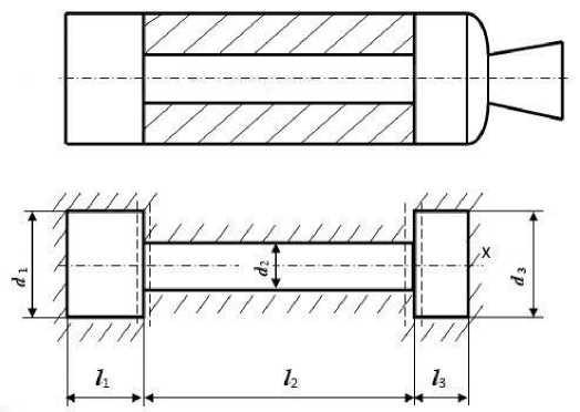
Fig. 1. Diagram of the gas cavity of the chamber: a – constructive; b – calculated
Рис. 1. Схема газовой полости камеры: а – конструктивная; б – расчетная
The propagation of vibrations in such a complex cavity is accompanied by diffraction phenomena. Considering that most of the sound wave approaching the nozzle is reflected from it into the chamber (due to the presence of a converging part of the nozzle and a change in the acoustic resistance of the medium ρc) to simplify the considered oscillatory system, we replace the nozzle with a rigid wall. We divide a complex gas cavity into three cylindrical cavities, each of which has a constant cross-sectional area. For each component of a complex cavity, we represent the solution of the wave equation. Further, for the natural frequencies and the distribution of vibrational pressures and velocities, we use the method of “stitching” acoustic fields at the boundaries of the cavities [13], taking into account the continuity of the medium during the transition of a sound wave from one cavity to another. For example, the conditions for the continuity of the medium during the transition from the first cavity to the second are determined by the equality of sound pressures (or velocity potentials) at х = l1
* , ( / 1 ) = * n ( / 1 ) (22)
and the equality of the volume velocities
S f^l, s 2 f®*) , (23)
-
V d x j V d x j 2
where S 1 and S 2 – are the cross-sectional areas of the first and second cavities.
The solution of the wave equation for a complex three-stage cavity should be written in the form of a series, taking into account the fact that there is a standing wave in the cavity and diffraction reflections of vibrations during the transition from cavity to cavity (at х = l 1 and х = l 2 ), i.e., for each cavity taking into account zero boundary conditions for vibrational velocities at x = 0 and х = l 1 + l 2 + l 3 . If to simplify the problem we neglect the diffraction of acoustic waves at the joints of the cavities, then the solution of equation (21) for standing waves in each cavity can be written in the form
-
* i = Ai [k(x-ai)]el™t,(24)
i – is the number of the cavity, α i – is the parameter that determines the conditions for the phase transition from cavity to cavity; A i - vibration amplitude.
For the first cavity
-
* , = A, [ k (x -a,)] em t.(25)
From the zero boundary condition for the vibrational velocity v = 0 x = 0 it follows that α 1 = 0. Hence
-
* , = A, cos (kx) elm t,(26)
And for the second cavity
-
* 2 = A2 cos [ k (x - a2 )] eto t.(27)
Similarly for the third cavity
-
* 3 = A3cos |^ k (x-a3)] evto t.(28)
However, from the zero boundary condition for the vibrational velocity
-
v- = ^*3, = о при х = / , + / 2 + / з следует, что a3 = / , + / 2 + / 3.
d x /k
The unknown wavenumber k and the parameter α 2 can be determined by substituting expressions (26) and (27) into conditions (22) and (23), which characterize the continuity of the medium at x = l 1 . Eliminating the coefficients A 1 and A 2 from the system of equations, we obtain the relationship of the unknown parameters
S tg k/1 = -TTtg [ k (/1 -a2 )]. (29)
S 1
The conditions for “matching” acoustic fields at x = l 1 + l 2 are fulfilled similarly to conditions (22) and (23):
^ 2 ( l1 + l 2 ) = V 3 ( l 1 + l 2 ) ; S 2

= S 3

Eliminating the amplitude coefficients A 2 and A 3 , we obtain the second equation for determining the unknowns k and the parameter α 2
S 3 tg kl 3 + tg [ k ( l i + l 2 -а ) ] = 0. (31)
S 2
Solving algebraic equations (31) and (33) together, we obtain the transcendental algebraic equation tgkl2 + S1 tgkli + S3 tgkl3 - S • S3 tgkli • tgkl2 • tgkl3 = 0.
S 2 S 2 S 2
Dependence (32) includes the geometrical dimensions of the gas cavity and the unknown wave number k .
The distribution of the amplitude of pressure fluctuations (in relative values) along the length of the com- bustion chamber can be determined by the following formulas:
for the first cavity:
§ p 1 = p = cos kx ;
p 0
for the second cavity:
s p 2
8p 2 =--=
p
cos kl 1
cos [ k (l1 -а2)]
cos [ k ( x -
а 2 ) ] ,
where α 2 is calculated from equation (30)
kl 1 - arctg
α2
S
1 tg kl 1
S 2
k
For the third cavity:
8 P 3 =
P 3
p 0
cos kl 1 • cos [ k ( l 1 + 1 2 -а 2 ) ] r -.
-------------L r ,--------cos I k (x - а3 )l.
cos kl 3 • cos [ k ( l 1 -а 2 ) ] ^ ]
Here p 0 – is pressure amplitude at x = 0.
-
Fig. 2 shows the graph p / p 0 = f ( x ) according to the calculated data.
According to the described algorithm, approximate calculated dependences can be obtained for other configurations of the gas cavity of the combustion chambers. Comparing the calculated data found by approximate formulas with the experimental data obtained on an acoustic installation, one can find out the accuracy of the calculations. The tasks of the experimental work include the determination of the natural resonances of the acoustic longitudinal mode and the estimation of the vibrational energy losses.
Description of the test unit
The test unit consists of a model chamber, an electrodynamic emitter, a sound generator that sets the excitation frequency, an amplifier, and receiving and recording equipment.
The model chamber is split and consists of several sections. Charge dummies can be inserted inside the chamber. The geometric dimensions of the acoustic cavity are shown in Fig. 2.
Sound heads of the 10 GRAD-5 type are used as a source of small vibrations. The frequency range of these heads ranges from 90 to 12,000 Hz. The sound heads are powered from the UM-50A type amplifier. A sound generator of the GZ-18 type is used as a master oscillator. Receiving and recording equipment includes a pressure sensor and a computer. The sensing part of the detector is a hollow piezoceramic ball with a diameter of 7 mm and a wall thickness of 0.25 mm. The dimensions of the detector's sensitive element are chosen so that they are an order of magnitude smaller than the measured wavelengths, in order to avoid distortion of the sound field.
The method of procedure
In operation with the help of an electrodynamic emitter, vibrations of a certain frequency in a given range are excited. To obtain the acoustic characteristics of the chamber at different moments of engine operation, experiments are carried out with several charge mock-ups having different sizes (imitating the burnout of the charge). For each version of the gas cavity, by tuning the sound generator, the amplitude-frequency characteristic is taken within the limits of the first two resonances of the longitudinal vibration mode. The frequency response is used to determine the natural frequencies of the camera. At the same frequencies, the distribution of the amplitude of the oscillatory pressure for the longitudinal mode of oscillation is recorded using a sensor moved along the axis of the chamber.
Sequence of calculations and processing of experimental data
-
I. Calculation of the acoustic characteristics of a model combustion chamber:
– the lowest values of the wave number k are determined by the formula (32) (using auxiliary tables) and the natural frequencies of longitudinal vibrations are calculated according to the formula
kc 0
J 2n .
When calculating the vibration frequency on an acoustic model installation, the speed of sound in air is taken, and for a natural combustion chamber, the speed of sound should be calculated in combustion products;
-
– the amplitude of pressure fluctuations in relative values is calculated (attributed to the pressure amplitude p 0 at х = 0) according to formulas (33)–(36), (Fig. 2);
-
– approximate determination of acoustic energy losses in the combustion chamber. The loss of acoustic energy per unit time, dE / dt is proportional to the energy density E . Denoting the coefficient of proportionality through 2δ, we have dE / dt = 2δ E , whence integrating we find
E = E0 exp (-25t), where E0 – is energy density at the moment t = 0.
The pressure amplitude due to losses in the oscillatory system decreases exponentially t —51
P = P 0 e
.
dE
The magnitude 5 = ^ is the attenuation coefficient for the longitudinal mode and characterizes the acoustic energy loss per unit time. Approximately the damping coefficient δ can be determined, having the amplitude-frequency characteristic of the oscillatory system, by the value of the quality factor Q [2; 6]. It should be noted that Q is a characteristic of a linear system with lumped parameters, but conditionally Q can be used as a characteristic of nonlinear systems with distributed parameters. The value of Q represents the ratio of the time-average available energy to the amount of energy loss over the period of oscillation [2; 6–8; 14–15], there-n to 2n fore Q =----, or Q = —, here T = — is the period of fluctuations. The quality factor of the oscillating sys-
5-T 25to tem, having an amplitude-frequency characteristic, can be determined from the width of the curve (Fig. 3) (f1 –
.
fi ) at a level equal to --- p , according to the formula Q =----
2 'max
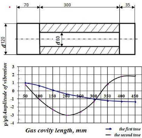
Fig. 2. Distribution of vibrational pressure in the gas cavity of the chamber (according to calculated data):
1 – the first tone of the longitudinal mode; 2 – the second tone of the longitudinal mode
Рис. 2. Распределение колебательного давления в газовой полости камеры (по расчетным данным):
1 – первый тон продольной моды; 2 – второй тон продольной моды
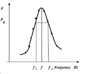
Fig. 3. Determination of the quality factor Q by the amplitude-frequency characteristic of the oscillating system
Рис. 3. Определение добротности Q по амплитудно-частотной характеристике колебательной системы
From the above expressions for Q we obtain 5 = n ( f 2 - f 1 ) .
If the combustion chamber is filled with gas with such characteristics that the ratio is fulfilled
( RT ) k k k S1
( RT Ld kmod” , then in model experiments the vibration frequencies and loss characteristics will be simulated which are close to those occurring in the combustion chamber of a running engine (counting losses with flow through the nozzle small).
-
II. Construction of acoustic characteristics of a model combustion chamber based on experimental data.
-
1. Graphs of the amplitude-frequency characteristics of the combustion chamber are constructed.
-
2. A graph of the natural frequency of vibrations of the combustion chamber is constructed as a function of the ratio of the diameter of the charge channel to the diameter of the combustion chamber.
-
3. Graphs p / p 0 = f ( x ) are plotted for the first and second tones of the longitudinal mode.
-
4. A graph of the attenuation coefficient is plotted as a function of the ratio of the diameter of the charge channel to the diameter of the combustion chamber.
Conclusion
A method of computational and experimental approximate determination of the acoustic characteristics of the combustion chambers of solid-propellant rocket engines has been developed, without taking into account the effect of solid propellant combustion. Taking into account the high costs of creating a T-shaped experimental solid propellant rocket engine combustion chamber and the significant difficulties in conducting such experimental studies, the proposed algorithm makes it possible to determine the frequencies of natural acoustic resonances in the cavities of solid-propellant rocket engines, in particular for the longitudinal mode, less costly in time and money, and to predict their coefficients ( decrements) damping.
References A technique for determining the acoustic characteristics of combustion chambers of a solid propellant rocket engine
- Zel’dovich Ya. B., Barenblatt G. I., Librovich V. B., Mixviladze G. M. Teoriya nestacionarnogo goreniya poroxa [Theory of non-stationary combustion of gunpowder ]. Moscow, Nauka Publ., 1980, 478 p.
- AbugovD.I., Boby`lev V. M. Teoriya i raschet raketny`x dvigateley tverdogo topliva. [Theory and calculation of solid-propellant rocket engines]. Moscow, Mashinostroenie Publ.,1987, 272 p.
- Kouts F. L., Xarton M. D. [Analysis of the stability of the working process in the design of RDTT]. Voprosy` raketnoy texniki. 1969, No. 7, P. 11–28 (In Russ.).
- Barrer M., Nado L., LyujnerI. [Studies of the instability of combustion of RDTT fuels]. Voprosy` raketnoy texniki. 1973, No. 7, P. 10–28 (In Russ.).
- BloxincevD.I.Akustika neodnorodnoj dvizhushheysya sredy` [Acoustics of an inhomogeneous moving medium]. Moscow, Nauka Publ.,1966, 205 p.
- Doroshenko V. E., Furletov V. I. [On the effect of sound on a turbulent flame]. Fizika goreniya i vzry`va. 1969, No. 1, P. 114–121 (In Russ.).
- Biryukov V. I., Mosolov S. V. Akustika gazovy`x traktov zhidkostny`x raketny`x dvigateley. [Acoustics of gas paths of liquid rocket engines]. Moscow, MAI Publ., 2013, 164 p.
- Biryukov V. I., Mosolov S. V. Dinamika gazovy`x traktov zhidkostny`x raketny`x dvigateley. [Dynamics of gas paths of liquid rocket engines]. Moscow, MAI Publ., 2016, 168 p.
- Biryukov V. I., Nazarov V. P., Tsarapkin R. A. The Algorithm for Estimating Reserves of the Working Process Stability in Combustion Chambers of Liquid-Propellant Rocket Engines. Siberian Journal of Shience and Technology. 2017, Vol. 18, No. 3, P. 558–566 (In Russ.).
- Biryukov V. I., Tsarapkin R. A. Damping Decrements in the Combustion Chambers of Liquid-Propellant Rocket Engines. Russian Engineering Research. 2019, Vol. 39, No.1, P. 6–12.
- Biryukov V. I., Ivanov V. N., Tsarapkin R. A. Method for Predicting the Stability Limit to Acoustic Oscillations in Liquid – Propellant Rocket Engine Combustion Chambers Based on Combustion Noise. Fizika Goreniya i Vzryva. 2021, Vol. 57, No. 1, P. 80–89.
- Czarapkin R. A., Biryukov V. I. [Experimental determination of the attenuation constants in the combustion chambers of liquid rocket engines]. Vestnik mashinostroeniya. 2018, No. 10, P. 21–27 (In Russ.).
- Osipov A. A. [Propagation of three-dimensional acoustic perturbations in channels of variable cross-sectional area at frequencies close to the cut-off frequency]. Izvestiya AN SSSR.Seriya Mexanika zhidkosti i gaza. 1980, No. 6, P. 149–159 (In Russ.).
- Rudenko A. N. [Experimental study of the frequency characteristics of nozzles with respect to longitudinal and transverse vibrations]. Akusticheskiy zhurnal. 1979, Vol. 20, No. 6, P. 897–906 (In Russ.).
- Sukhinin S. V., Akhmadeev V. F. Self Oscillations in the Gas Cavity of a Solid Rocket Motor. Fizika Goreniya i Vzryva Combustion. 2001, Vol. 37, No. 1, P. 42–52.
