A two-level method for calculation of microstress on reinforced plates with circular hole in case of extension normal to principal direction

Author: Darya Zadeh S., Lvov G.I.
Article in issue: 1, 2015.
Free access
The stress concentration must often be examined at two levels while analyzing the stress condition of composite materials. The macroconcentration depends on the presence of holes, notches and other local areas of a construction. Typical dimensions of macroconcentration distribution areas are of the order of 0,01-0,1 m. Macroconcentration analysis is performed using the models of homogeneous material. Microstress concentration occurs in structurally inhomogeneous composites due to the structural heterogeneity of the composite. The sizes of concentration areas in regular structures are defined by the sizes of periodically recurring areas. In fibrous composites, such areas have the size of approximately 0,0001 m or less. This makes it necessary to use a two-level approach for the analysis of the stress concentration in the construction of composite materials. The aim of the present study was to compute the stress concentration in unidirectional reinforced composite plate with circular hole with respect to the volume ratio of the component materials in composite. The contour of the circular hole and its dependency on the structure of plates was calculated in order to study the behaviors of macro- and microstresses. The boundary conditions at a large distance from the hole are pressure, uniformly distributed on the plate. Also this problem is analyzed with the finite element method by package ANSYS. Macroconcentration is defined based on the solution of the plane problem of elasticity theory of the orthotropic material by the virtue of functions of a complex variable. The finite element method was used to investigate the stress distribution at microlevel. Boundary conditions that model the state of the specified two-dimensional representative cell in the composite structure were established. The results demonstrated the macro- and microstresses and behavior of the orthotropic plate with a circular hole calculated for two different structures.
Composite plate, unidirectional reinforced, numerical method, boundary conditions, stress concentration
Short address: https://sciup.org/146211547
IDR: 146211547 | UDC: 539.3 | DOI: 10.15593/perm.mech/2015.1.10
Text of the scientific article A two-level method for calculation of microstress on reinforced plates with circular hole in case of extension normal to principal direction
PNRPU MECHANICS BULLETIN
The stress concentration behavior in composite plates with holes is always one of the important issues in solid mechanics. Composite materials which consist of two or more constituent materials are commonly used in advanced structural applications, e.g. in the marine and aerospace industry. This is because of appropriate mechanical properties such as high specific strength and stiffness, low density and high resistance to corrosion. However, the limited understanding of the composite material behavior requires more research. This is further complicated by the fact that the behavior of these materials is dependent on lay-up, loading direction, specimen size and environmental effects such as temperature and moisture. The design of fiber composites which originated from the principles of micromechanics can be further modified to provide desired performances of composite structures. Holes in composites plate will create stress concentration and hence will reduce the mechanical properties. The solution of the elastic plate theory by the complex functions allows for the solution of isotropic and anisotropic plates with holes. The use of complex variables was first introduced by Muskhelishvili [1]. The functions used for the problems will satisfy the desired boundary conditions. The purpose of this research was to compute the stress concentration around the hole in a composite plate based on the theory of elasticity anisotropic materials by the application of complex functions Lekhnitskii and Savin [2, 3].Through this method and the boundary conditions of pressure distributed, the stress concentration is calculated around the hole in orthotropic plates. Greszczuk studied the stress concentration factors around the hole in orthotropic plate. In his research, stress is applied in one of the principal material directions. Furthermore, he plotted the circumferential stress around the hole for an isotropic material and several unidirectional composite materials [4]. In the literature (for instance in [5–7]) analytical solution for the calculation of composite plates with holes for various cases of load conditions can be found based on the fundamental works of Lekhnitskii. Experimental results of the tensile strain field around circular hole in a composites plate by Toubal et al. [8] was compared with the predictions of a theoretical model previously developed by Lekhnitskii and a finite element study. For a plate containing a hole that is subjected to uniaxial tension or out-of-plane bending, the sensitivity of the stress and strain concentration factors to plate thickness as well as the Poisson’s ratio or moment ratio were done by Yang et al. [9, 10] and Yang [11]. Rhee et al. Moreover, [12, 13] examined extensive experimental and numerical studies. For determining the stress concentration around circular, elliptical holes in composite infinite plate subjected to arbitrary uniaxial and biaxial loading at infinity using finite method obtained in works [14–18]. The study will be using complex functions [19] to determine the effective elastic coefficients of the plates as presented by Vanin (1961). Subsequently, the stress around a circular hole in an orthotropic fiber-reinforced plate is calculated with respect to the volume ratio of the component materials in composite [20].
Numerical methods for calculating the composite material properties typically involve analysis of a representative volume element and a great number of micromechanical models that have been proposed for predicting various mechanical properties of composite materials [21–29].
Next, the micro-stress is calculated around the hole in the plate. The purpose of this paper is to present computational analysis method of micromechanics of strength of materials and to demonstrate its applications to various micromechanical problems. In this work, the results of the numerical calculations were presented for micro-stress concentration of the different materials in the orthotropic plates for square and hexagonal structures with respect to the volume ratio of the component materials in the composites.
In this report, the finite element method was used to approximate the different elastic properties of the fiber-reinforced composites. A theoretical method and ANSYS (ANSYS, Ver. [11], [NTU «KHPI» company EMTU, Kiev, 2010.])was used to calculate the results of the numerical stress distribution.
1. Stress distribution in infinite orthotropic plate with one circular hole in case of extension normal to principal direction
Consider a composite infinite plate with a circular hole, which was extended by a uniformly distributed pressure P (per unit area) applied at a large distance from the hole. The polar system coordinate is in the center and point o and θ angle is assumed to be on axle x (Fig. 1).
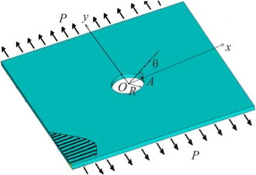
Fig 1. Illustrates the reinforcement plate with a circular hole be extended by pressure P
The composite plate consists of two phases in the matrix-reinforcement. The reinforcing fi- bers in an orthotropic in finite plate are aligned unidirectional. It is assumed that the main axis of elasticity is the x-axis. The stress concentration in anisotropic plates with holes was first cal- culated by Lekhnitskii (1968) using complex functions. Lekhnitskii presented the solution method and related formulas. For ease of use and simplification of formulas, the following rela- tionships are used [2]:
EE
m = —— -2и,; k = —1; n = V2k + m;
G 12 12 E 2
E^
sin4 0
--+
E 1
( 1

a A -4
2u12 -2a 2 A Sin
--12 sin2 0 cos2 0 +----
E 1 J E 2
E θ – Young module for tangent (shear) direction; E 1 and E 2 is Young’s modulus of elasticity for the principal axis and along the y -axis; ν 12 and G 12 are the Poisson’s ratio and the shear modulus on x О y plate.
In this document, the problem is studied in linear elasticity mode and the problem is solved for the plate by applying a uniform pressure P on the boundary of plate at a large distance from the circular hole along the y -axis. Lekhnitskii provided an expression for circumferential stress around of the circular hole as follows [2]:
g6 p E- [[- ( k + n ) k cos2 6 | - k sin2 6 ' , (2)
σ θ – Circumferential stress and the coordinate is evaluated based on axle x .
Obviously, the stress concentration at point A is (Fig. 2):
K 1 =? »№. (3)
In the area of numerical calculations, four types of composite plates were examined including 1 – carbon fiber plate with aluminum-iron matrix and high-strength carbon fibers, 2 – fiberglass plate with epoxide matrix and glass fibers, 3 – epoxide resin matrix and epoxide reinforcement and 4 – carbon fiber plate with carbon fiber and epoxide resin matrix. Table classifies the mechanical properties of the orthotropic plates in square array for ξ = 0,488 [30], where ξ – the volume ratio of the component is given by:
5 = 2 ? ■ , (4)
w1 • b • sin a
G m , G a are shear modulus of the matrix and reinforcement, respectively, r – is the radius of the reinforcement 0 < α ≤ π/2 and b > 0.
The longitudinal and transverse distance between two reinforcements is equal to W 1 and W 2 = W 1 bei α , respectively. The present work is based on the volumetric occupancy coefficient in square and hexagonal arrangements [19].
The angles are between the two vectors in the square α = π/2 and hexagonal α = π/3 arrangements for b = 1.
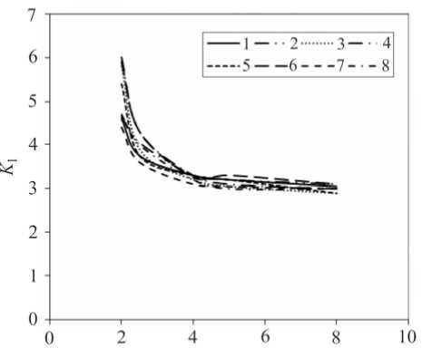
Fig. 2 shown the stress concentration around the circular hole versus w 1 / r for b = 1 in the case: uniaxial tensile loading along the y -axis for a unidirectional fibers plate with a hole by the theoretical method. The four orthotropic plates composed of the different plates with the properties are listed in Table for both square and hexagonal arrangements.
Wx!r
Fig. 2. Stress concentration around the hole as a function of w 1 / r while applying uniform pressure along y -axis when b = 1; 1 , 3 , 5 and 7 : the charts for materials I, II, III and IV for the square arrangement, 2 , 4 , 6 and 8 : the charts for materials I, II, III and IV for the hexagonal arrangement
Mechanical characteristics of the orthotropic plate when w 1 = 2,5 a , b = 1 and ξ = 0,488
|
Number’s materials |
G a / G m |
E 1 , MPa |
E 2 , MPa |
G 12 , MPa |
ν 12 |
|
I |
2,49 |
173 500 |
156 900 |
53 790 |
0,32 |
|
II |
20,6 |
38 380 |
11 190 |
2800 |
0,3 |
|
III |
28,4 |
35 420 |
6350 |
1780 |
0,31 |
|
IV |
68,48 |
116 400 |
9220 |
2540 |
0,31 |
2. Micro-stress Concentration While Applying Uniform pressure at a large distance from the hole in an Infinite Orthotropic Plate
The micro-stress concentration exerted on the plane will be examined. The internal structure of the composite plate was considered and the cells were examined. The arrangements of the cell of the plate on the contour hole at the point where macro stress existed was considered as well. Also, the micro-stress concentrations in the orthotropic plates were calculated, considering the boundary conditions [5, 8–12]. The results were dependent on the internal shape of the plate and the volume ratio of the components, but the analysis was performed by the ANSYS.
Below the finite element modeling and analysis of a composite plate with a circular hole for unidirectional fibers using ANSYS is discussed. The plate is meshed with PLANE182 elements with four nodes and two degrees of freedom per node in x and y directions in plane xy by 10031 elements [31]. Because of the symmetry for this solution, only the quarter models or cell models were considered and illustrated in Fig. 3 [14].
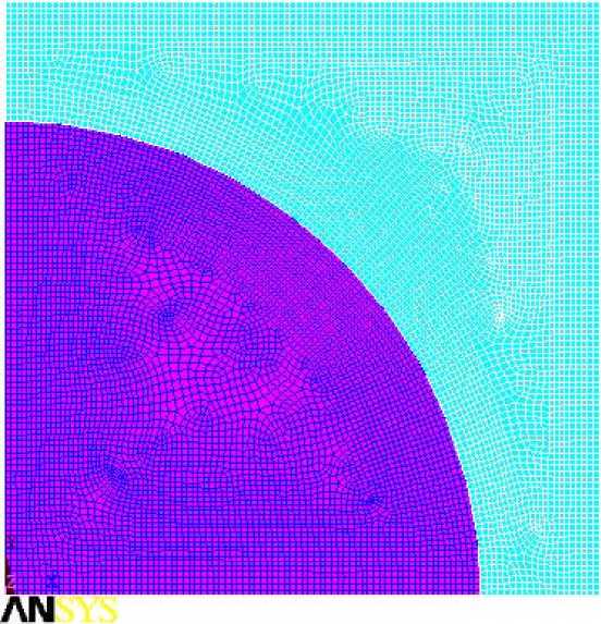
Fig. 3.The quarter model for an embedded cell meshed with PLANE2 finite element
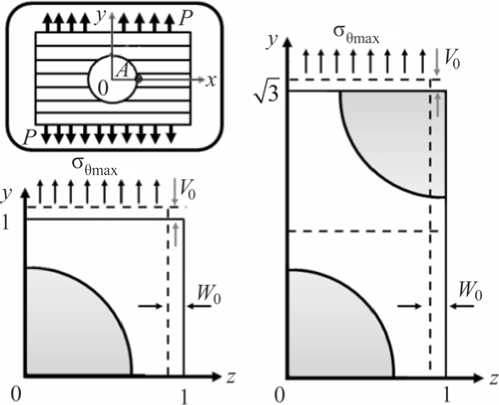
A regular two-dimensional arrangement of fiber in a matrix was adequate to describe the overall behavior of the composite, and was modeled as a regular uniform arrangement, as illustrated in Fig 4. This model assumed that the fiber was a perfect cylinder of radius 0,79, in a square (1 × 1) for the square array and for a hexagonal (1 × 3 ) of the matrix. It is assumed that the geometry, material and loading of the unit cell are symmetrical with respect to y-z coordinate system as shown in Fig 4. Therefore, 48,8 % volume fraction fibers were inserted into the square matrix uniformly.
a b
Fig. 4. Representative cell model for: a – square; b – hexagonal fiber arrangement
In this case, assuming an element is at point A and a stress σ θ max , was applied on it, while the change in the arrangement of the element is studied in both square and hexagonal arrangements (Fig. 4). The element is located on the edge of the plate at point B. Following the exerted pressure, stress σ z = σ θ max , given the arrangement of the plate, the line y = 1 will decrease along the y -axis by ν 0 , while z = 1 or z = 3 will increase along the z -axis by w 0 .
Subsequently, the boundary conditions are conditions of the periodicity of mechanical fields in view of the deformation:
On the line y = 1 for the square and hexagonal arrangements:
(° y ) = J° y dz = 0, (° y ) J ° y dz = 0. (5)
Therefore, on the line z = 1, z = 3 for the square arrangement and hexagonal arrangements:
( °z) = J °zdy = P•
On the lines y = 0: ν 0 = 0 and z = 0: w 0 = 0. The conditions (5), (6) are established due to uniform macro stress state.
Now, the micro-stress concentration K (micro) is obtained using Eq. (7):
K-.= ^ (micro)
Mises
° (max)
° 6 (max)
The displacements (8) satisfy the boundary conditions (5), (6) on the cell for a fiberglass plate with square arrangement while applying uniform pressure normal to fiber axis, P = 100, on the boundary of the hole:
' У = 1: v = - 0,174 - 10 — 7, _ z = 1: w = 0,55 - 10 - 7.
In this case Fig. 5 shows the calculation of the resultant stress σ y , and the stress σ z on a cell using finite element method with the help of ANSYS.
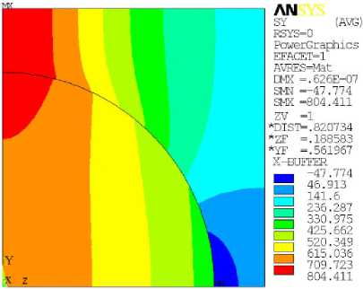
a
Fig. 5. The stress: ( a ) - a y , ( b ) - ст z on the cell consisting of matrix-reinforcement for a fiberglass plate with square arrangement when P = 100
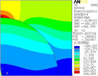
b
Fig. 6 shows the von mises stress on a cell consisting of the matrix-reinforcement for a fiberglass plate with a square arrangement in the case of uniform stress P = 100 distributed along normal to the x- axis in the orthotropic plate for ξ = 0,488. The numerical calculations were carried out by ANSYS. For most real structural components made of glass-fiber material diameters of fiber significantly smaller than the diameter hole, around which there is a concentration of macro-stress. For such cases, you can ignore the macro-stress gradient in the representative cell.
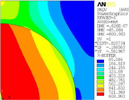
Fig. 6. The von mises stress on the cell consisting of the matrix-reinforcement for a fiberglass plate with a square arrangement when P = 100
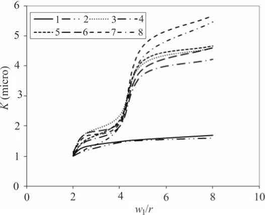
Fig. 7. Micro-stress concentration around the circular hole as a function of w 1 / r while uniform pressure is applied along y -axis when b = 1; 1 , 3 , 5 and 7 : the charts for materials I, II, III and IV for the square arrangement, 2 , 4 , 6 and 8 : the charts for materials I, II, III and IV for the hexagonal arrangement
The micro-stress concentration around the circular hole versus w 1 / r for b = 1 when loading normal to the principal axis by the finite elements method is shown in Fig. 7. The four charts for the orthotropic plates are composed of various materials.
3. Result and discussion
In the case of uniaxial tensile unidirectional plate which is normal to the principal axis, the stress concentration near a hole decreases with an increase in the distance between the centers of reinforcements. It will tend to 3, which indicates the stress concentration in an isotropic plate. The stress concentration of the hexagonal arrangement is higher than the square arrangement. The micro-stress concentration near the circular hole increased from 1 when the distance between the centers of the reinforcements was increased. On the other hand, the micro-stress concentration in the square arrangement is higher than the hexagonal arrangement.
Depending on the type of reinforcement and direction of the applied load possible highest stresses appearing at other points of the plate. This requires an analysis of equivalent stress in the entire study area.
The results of this research done on the four plates with the differentiating specifications, confirmed the dependence of the results to the ratio, ξ, a character of the properties in these constituents. The proposed method can be applied to composite materials with different structures for which can be secreted representative volumes.
Conclusion
In this paper a numerical approach to the study of stress concentration in composite plates with circular holes is developed. The feature of the proposed approach is to analyze the stress concentration at two levels. The analyses the concentration of macro-level composite is however, considered as a homogeneous orthotropic material. Analysis of micro-stress concentration is made at the level of the minimal repetitive structure of the composite. For square and hexago- nal fiber reinforcement representative cell is allocated and boundary conditions are formulated for simulating the stress state of the cell as part of a homogeneous material.
The influence of the fibers filling degree on the micro- and macro-concentration has a different character. With the reduction of the filling degree, the elastic properties of composite verge towards those of the isotropic binder. Therefore, the coefficient macro concentration tends asymptotically to 3. At the same time, with the reduction of the filling degree the coefficient micro concentration increases continuously. This is due to the fact that when fibers are stretched along its, they undertake more load because of the greater rigidity.
Stress intensity in the most dangerous point is determined by the product of stress concentration factor of micro and macro levels.
Finally, the developed approach makes provision for the determination of the allowable load based on the actual distribution of stresses in thin-walled structural elements which are made of composite materials.
