Acoustic performance analysis of diesel engine silencer

Author: Liu Fangzhou
Journal: Бюллетень науки и практики @bulletennauki
Section: Технические науки
Article in issue: 2 т.9, 2023.
Free access
The finite element model of diesel engine muffler is established, the noise reduction function of the muffler is studied and tested, the distribution cloud diagram of sound pressure level inside the muffler is calculated, the sound fields at various frequencies are plotted. The change of sound pressure level inside the muffler is tested. After processing, the line spectrum and octave band results of the transmission loss of the muffler are obtained. The acoustic performance of the muffler can be quantitatively determined by synthesizing the results of the sound field distribution and the transmission loss inside the muffler.
Silencer, cloud diagram of sound pressure level distribution, frequency sound field, transmission loss
Short address: https://sciup.org/14126765
IDR: 14126765 | UDC: 534.83 | DOI: 10.33619/2414-2948/87/24
Анализ акустических характеристик глушителя дизельного двигателя
Создана конечно-элементная модель глушителя дизельного двигателя, исследована и испытана функция шумоподавления глушителя, рассчитана облачная диаграмма распределения уровня звукового давления внутри глушителя, построены звуковые поля на различных частотах. Тестировалось изменение уровня звукового давления внутри глушителя. После обработки получен линейчатый спектр и результаты октавной полосы пропускания глушителя. Акустические характеристики глушителя можно количественно определить путем синтеза результатов распределения звукового поля и потерь при передаче внутри глушителя.
Text of the scientific article Acoustic performance analysis of diesel engine silencer
Бюллетень науки и практики / Bulletin of Science and Practice
UDC 534.83
Diesel engine is widely used in daily life. Silencers play an important role in noise reduction of diesel engines. In order to accurately analyze the acoustic performance of diesel engine exhaust muffler, the finite element software is used to simulate the muffler in the acoustic frequency domain, and the transmission loss is used to evaluate the acoustic performance of the muffler, so as to realize the low-noise design of the generator set.
Silencer Design Parameters
-
(1) Analysis of spectrum characteristics of noise sources
Use professional noise testing equipment to test the overall radiated noise of the engine. The layout of main measuring points is shown in Figure 1. Measuring points 8 and 9 are arranged at the

engine exhaust port for exhaust noise measurement. The measurement results of exhaust noise are shown in Figure 2.
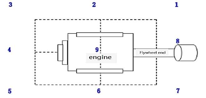
Figure 1. Radiated Noise Test of Engine
The spectrum measurement results of exhaust noise are shown in Figure 2. According to the analysis of the measurement results, the maximum exhaust noise is about 80 dB (A), and the noise amplitude is above 70 dB (A) in the frequency range of 500-4000 Hz. The noise amplitude in other frequency bands is low.
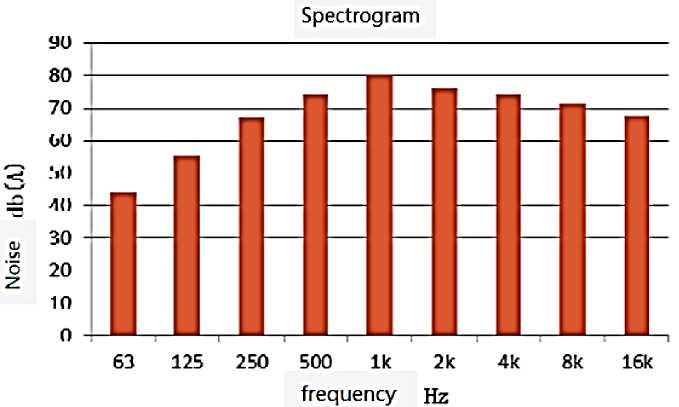
Figure 2. Measurement Results of Exhaust Noise Spectrum
-
(2) Design silencer parameters
In order to effectively control the impact of engine exhaust noise on the overall radiated noise, the most effective method is to install a muffler. According to the exhaust noise characteristics, the exhaust muffler is designed as a multi chamber resistant muffler.
The three-dimensional model of muffler is shown in Figure 3. The upper connection port in the figure is the air inlet, which is connected with the engine exhaust pipe. The air inlet pipe and the air outlet pipe are provided with perforated endotracheal tubes, and the interior of the chamber is separated into two noise elimination chambers by a perforated plate [1-4].
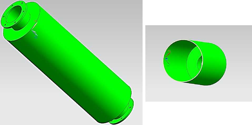
(a) Overall model of muffler (b) Internal structure of muffler
Figure 3. Three-dimensional model of muffler
Acoustic Finite Element Modeling and Simulation of Muffler
-
(1) Pretreatment of simulation model
The boundary conditions of hard sound field are generally used in muffler simulation, so the fluid domain inside the muffler needs to be filled to obtain the internal fluid domain model. Due to the large influence of grid accuracy in the simulation, the model needs to be simplified. The simplified muffler model is shown in Figure 4. The inlet and outlet planes are set in the software, and the Fill command is selected to fill the interior of the muffler. The fluid domain model is shown in Figure 5.
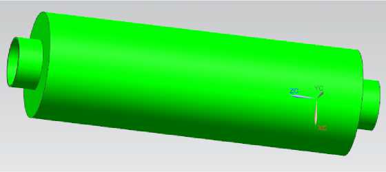
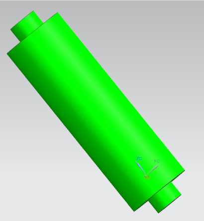
Figure 5. Fluid Domain Model in Silencer
Figure 4. Simplified Model of Silencer
-
(2) Acoustic gridding
In the software pressure acoustic module, the fluid domain filling model of the muffler is imported, and the geometric domain of the model is divided. According to the acoustic grid requirements, tetrahedral grid and triangular surface grid are adopted for the grid type, and triangular surface grid is adopted for the internal narrow area and opening area. The joints of each part are densified to avoid generating too low mass elements. The finite element mesh model of the muffler is shown in Figure 6.
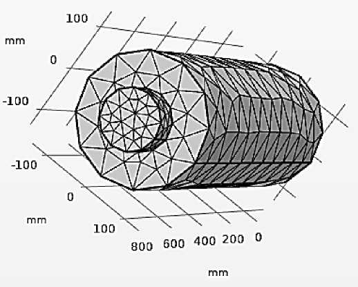
Figure 6. Finite Element Mesh Model of Silencer
After the grid is divided, the grid quality distribution map is drawn in the grid tool, and the analysis shows that the overall unit size of the muffler grid model is controlled below 1mm, the minimum grid unit size is 0.1mm, the overall quality is good, and there are no low-quality units and regions.
Simulation Boundary Conditions
-
1) Boundary condition of sound field
For the solid boundary, that is, the outer wall of the muffler chamber and the pipe, the hard sound field (wall) boundary condition is used, and the normal velocity imposed on the boundary by this condition is zero.
-
2) Import and export boundary
The model uses port boundary conditions to simulate the inlet and outlet of the muffler. The port type is circular, and the incident excitation is 1Pa.
-
3) Parameter setting
Plane wave with inlet pressure of 1 Pa, sound velocity c=340 m/s, temperature T=293.15 K, and frequency calculation range of 50-8000 Hz.
-
(4 ) Analysis of simulation results
-
1) Sound field distribution
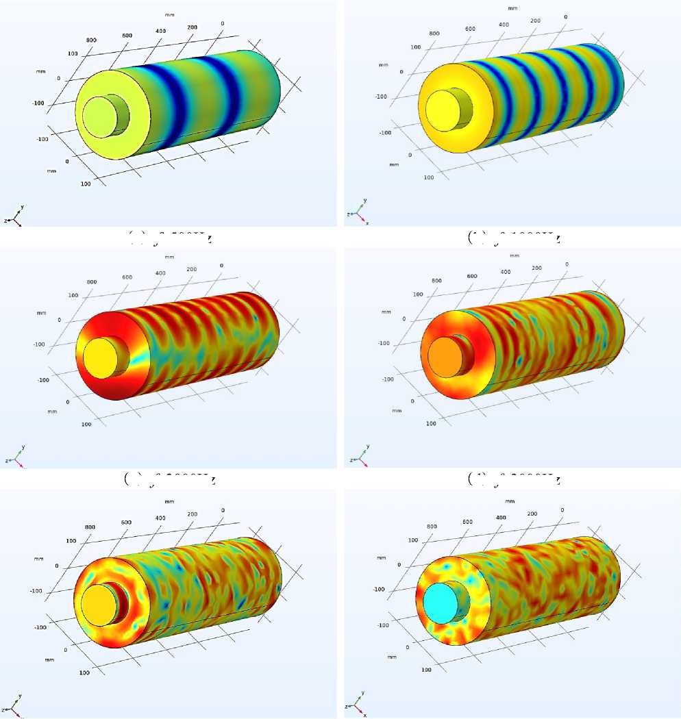
After the boundary conditions are set, the distribution cloud diagram of the sound pressure level inside the muffler is obtained through calculation. The sound field distribution at various frequencies inside the chamber is shown in the figures in Figure 7.
( a )
( b )
( c ) f =2000Hz
( d )
( e ) f =4000Hz
( f ) f =5000Hz
Figure 7. Distribution of Sound Field in Silencer
f =500Hz
f =1000Hz
f =3000Hz
The distribution of sound field inside the muffler is shown in Figure 7. When the calculation frequency is low, the sound propagation mode inside the muffler is mainly plane wave. With the increase of frequency, non-plane waves begin to appear inside the muffler. The low-frequency vanishing effect is good, and the sound pressure level inside the muffler changes obviously. The effect of high frequency noise reduction is reduced, resulting in a relatively low drop in the outlet sound pressure level compared with low frequency.
-
2) Transmission loss
After the result post-processing, the line spectrum and octave band results of the silencer transmission loss are obtained, as shown in Figure 8, 9.
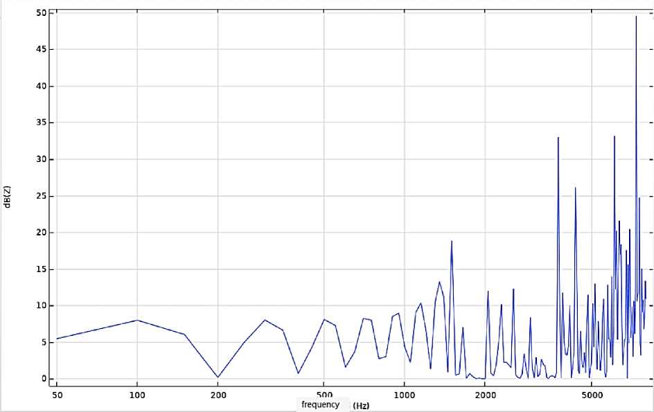
Figure 8. Transmission loss of muffler
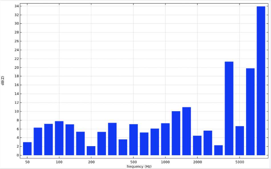
Figure 9. Transmission loss of muffler 1/3 octave
As shown in Figure 8 and Figure 9, the overall sound elimination effect of the muffler is good, and the sound elimination effect is good at about 5000Hz. The peak value of the transmission loss curve is obvious and the noise elimination frequency band is wide. The maximum value of the transmission loss is 50dB (A). With the increase of frequency, the noise elimination performance will
Бюллетень науки и практики / Bulletin of Science and Practice Т. 9. №2. 2023 decline after 5000Hz. Analyzing the octave results of transmission loss, it is found that the transmission loss has a high noise reduction in the 7000Hz frequency band. The overall sound elimination effect of the muffler is good, which can effectively control the engine exhaust noise, thus reducing the impact of the overall radiated noise.
Conclusion
Based on the results of sound field distribution and transmission loss in the muffler, the maximum transmission loss is 34dB (A). The muffler has good acoustic performance and can effectively control the impact of engine exhaust noise.
References Acoustic performance analysis of diesel engine silencer
- Liu Liping, Xiao Fuming, Lu Chen, Wang Zhuwei. Experimental Study on the Silencing Performance of Mufflers in the Presence of Air Flow // Internal-combustion engine Engineering. 2001. №01. P. 54-57.
- Middelberg J. M., Barber T. J., Leong S. S., Byrne K. P., Leonardi E. CFD analysis of the acoustic and mean flow performance of simple expansion chamber mufflers // ASME International Mechanical Engineering Congress and Exposition. 2004. V. 47152. P. 151-156.
- Jiang Pengming, Fu Xi, Wu Bangyu. Automotive muffler optimization design and comprehensive evaluation index [J]. Automotive Engineering, 2008,30(3) 247-257.
- Davis Jr, D. D., Stokes, G. M., Moore, D., & Stevens Jr, G. L. (1954). Theoretical and experimental investigation of mufflers with comments on engine-exhaust muffler design (No. NACA-TR-1192).
