Actuator made of a material with a shape memory effect for transformable space structures

Author: Zimin V.N., Krylov A.V., Filippov V.S., Shakhverdov A.O.
Journal: Siberian Aerospace Journal @vestnik-sibsau-en
Section: Aviation and spacecraft engineering
Article in issue: 1 vol.23, 2022.
Free access
Transformable structures represent a special class of large space systems. They are delivered into orbit in a tightly packed state. When the required parameters of the orbit are reached, their deployment or trans-formation is carried out. The shape of the transformed structure is rigidly fixed upon completion of the transformation process. At the same time, shock loads occur on its constituent elements. The complication of design schemes and the increase in the dimensions of modern transformable space systems due to the increase in their operational functionality leads to the necessity of improving their mass characteristics. At present, many variants of transformable structures of space antennas have been developed abroad and in our country, the ratio of the mass of mirrors to their areas has decreased to 0.5.–1.5 kg/m2. Further im-provement of transformable space structures is possible with the use of materials with the shape memory effect to create actuators that ensure controlled shock-free deployment of these structures from the transport state to the working position Experimental and theoretical studies of the actuator model made of titanium nickelide material have confirmed the fundamental possibility of its use for the deployment of promising transformable space structures. During the tests, the main characteristics of the actuator model were determined, namely: the actuation force, the working stroke and the actuation time.
Transformable space structure, active element, actuator, shape memory effect, material titanium nickelide, experimental studies
Short address: https://sciup.org/148329609
IDR: 148329609 | UDC: 629.8:531.395 | DOI: 10.31772/2712-8970-2022-23-1-73-80
Text of the scientific article Actuator made of a material with a shape memory effect for transformable space structures
ВведениеIntroduction
The design and creation of large space structures is associated with the solution of many technical and mechanical problems due to the uniqueness of the systems (Fig. 1).
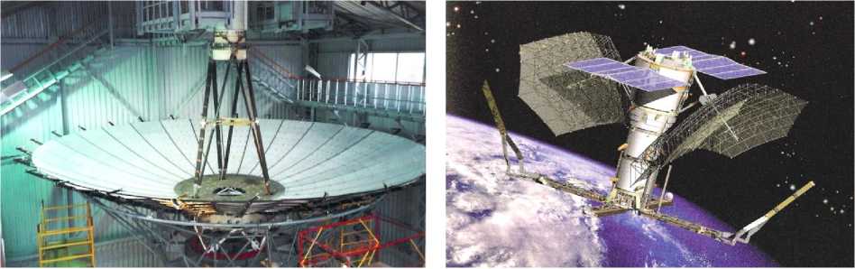
Fig. 1. Transformable large-sized space antennas
Рис. 1. Трансформируемые крупногабаритные космические антенны
The main feature is a combination of conflicting objectives: a significant increase in geometric dimensions and provision of the required rigidity with a very limited mass of material of the loadbearing frame [1].
Transformable large-sized space structures deployed in space, due to their overall dimensions, have a relatively large mass, which creates great difficulties with their delivery to orbit. The inevitable complication of structural schemes of promising transformable large-sized space systems due to increased requirements for their operational functionality, ensuring the rigidity of structures in the working position, maintaining the original geometry during operation can lead to an increase in their mass characteristics. The task of reducing the mass characteristics of such structures is undoubtedly relevant.
By now significant progress has been made in the field of creating large-sized space antennas associated with an increase in the deployment factor (the ratio of diameters in the working and transport positions) and the ratio of the mass of the reflector in working condition to its area [2–8]. Further minimization of the mass of transformable space structures is associated with the possibility of using materials with a shape memory effect (SME) to create drives both for their deployment and for controlling the shape of parabolic antennas [9; 10]. Another area of application of materials with SME is associated with the damping of vibrations of space structures.
It seems expedient to use the SME material as an active element of drives deploying large-sized transformable space structures. Actuators with an active element made of SME material will make it possible to control the deployment process, while eliminating the need to use all kinds of dampers to dampen shock loads that occur, for example, when using conventional springs that deploy the structure due to pre-stored elastic energy [11]. Actuators with an active element made of SME material can be made in the form of a wire, spring, or tape [12–14]. To determine the deformation-force characteristics of the active elements of the power drive, made in the form of a wire with a diameter of 1.5 mm from the titanium nickelide material, a set of experimental studies was carried out.
1. Experimental studies
Active elements were previously subjected to various types of heat treatment. Heat treatment was carried out in order to eliminate possible internal stresses. At this stage, the furnace heating temperature varied from 450 to 850 ºС. The time of heat treatment of active elements varied from 30 to 60 min, while cooling occurred in the oven. Next, a tensile force was applied to the active element, which created a tensile stress in its sections. Then the active element was heated by passing an electric current through it. The temperature of the active element at the moment it began to shorten its length was about 70–80 ºС. To evaluate the stability of the parameters of the active element of the power drive, such as the working stroke (reduction in the relative elongation of the active element) and actuation force (the force generated by the active element), the following tests were carried out. A tensile force was applied to the active element (Fig. 2 a ). Further, the active element was heated. Heating of the active element after deformation was carried out on the experimental installation shown in Fig. 2 b .
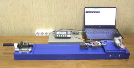
Fig. 2. Experimental intallations: a – for deformation of active elements; b – for determining the main characteristics of active elements
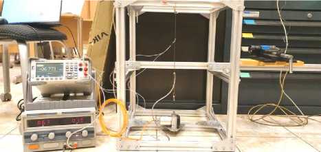
б
Рис. 2. Экспериментальные установки: а – для деформирования активных элементов; б – для определения основных характеристик активных элементов
During the tests, the following parameters of the active element were controlled: temperature, electrical resistance, working stroke and actuation force. Two methods were used to measure the temperature: contact and non-contact. In the contact method, a set of thermocouple sensors placed along the length of the active element was used. For non-contact temperature measurement, a thermal imager was used to measure the radiation of the active element in the IR range. In the process of experimental studies, it was found that non-contact temperature measurement has a significant advantage over contact measurement. When using the contact measurement method, a significant delay in the readings of the sensors was clearly recorded in comparison with the actual temperature of the active element recorded by the thermal imager.
The main functional parameters of a power drive with an active element made of a material with an SME are the force generated, the response time and the value working stroke. The value of the working stroke is determined by the change in relative elongation active element during its heating. The response time of the active element of the power drive is determined by the time of its heating to the temperature of the end of the reverse martensitic transformation. The table shows the experimentally obtained results of the response time of the active elements of the power drive with a change in the voltage supplied to them.
Response time of active elements of the power drive with a change in the voltage supplied to them
|
Ser. No. |
Working length (mm) |
Voltage (V) |
Current strength (A) |
Average response time (s) |
Working stroke (%) |
|
1 |
175 |
1.9 |
7.8–8.7 |
230 |
5.7 |
|
2 |
173 |
2.0 |
8.2–9.1 |
110 |
5.7 |
|
3 |
175 |
2.1 |
8.6–9.5 |
65 |
5.7 |
|
4 |
175 |
2.2 |
9.1–10.1 |
40 |
5.7 |
|
5 |
175 |
2.3 |
9.4–10.4 |
35 |
5.7 |
|
6 |
175 |
2.4 |
9.8–10.8 |
30 |
5.7 |
|
7 |
174 |
2.5 |
10.2–11.1 |
25 |
5.7 |
|
8 |
175 |
2.6 |
10.6–11.5 |
20 |
5.7 |
|
9 |
175 |
2.7 |
11.1–12.0 |
15 |
5.7 |
|
10 |
175 |
2.8 |
11.5–12.5 |
10 |
5.7 |
|
11 |
174 |
2.9 |
11.9–12.8 |
10 |
5.7 |
When the voltage of the power source changed, the response time of the active element of the power drive changed. However, despite the different response time of the power drive, the working stroke of the active element remained constant.
2. Drive operation model
At present, various models have been proposed that describe the kinetics of martensitic transformations, the patterns of accumulation and recovery of deformations under various interaction modes. However, the mathematical complexity of describing the behavior of materials with SME, the need to use a significant amount of actual experimental data in mathematical models has not yet allowed the development of engineering calculation methods of power drives with active elements made of SME materials [15; 16]. Therefore, the main role at present is played by experimental methods in the design of such power drives.
In the process of ground tests, it can be assumed that the change in the thermal energy of the active element of the power drive is equal to the amount of heat supplied by electrical energy, minus heat losses from natural convection cmdT = RI2 -aS(T-Tc), (1)
where c is the specific heat of the active element; m is the mass of the active element; T is the temperature of the active element; t is time; R is the resistance of the material of the active element; I is the current strength in the active element during testing; a is a heat transfer coefficient; S is the heat exchange surface area; T c is the ambient temperature.
When calculating the change in temperature of the active element of the power drive, the selection of the heat transfer coefficient was carried out. When conducting a numerical experiment, the results obtained correlated well with the results of experimental studies. The calculation took into account changes in the resistance and heat capacity of active elements during heating.
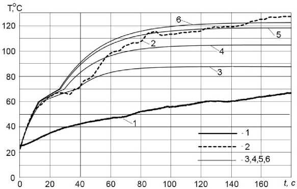
Fig. 3. Test results and numerical calculations of the temperature change of the active element:
1 – when measured by a thermocouple; 2 – when measured by a thermal imager;
3 – 6 – calculated with heat transfer coefficients α equal to 70, 55, 47 and 45
Рис. 3. Результаты испытаний и численных расчетов изменения температуры активного элемента: 1 – при измерении датчиком; 2 – при измерении тепловизором;
3 – 6 – при расчетных коэффициентах теплообмена α , равных 70, 55, 47 и 45
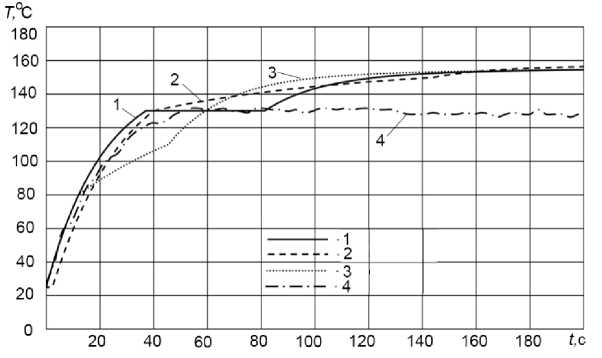
Fig. 4. Test results and numerical calculations:
1 , 2 – calculated with values of the coefficient k equal to 1, 0.5;
3 – change in the heat capacity of the active element;
4 – when measuring the temperature of the active element with a thermal imager
Рис. 4. Результаты испытаний и численных расчетов:
1 , 2 – при расчетных значениях коэффициента k , равных 1; 0,5;
3 – изменение теплоемкости активного элемента;
4 – при измерении температуры активного элемента тепловизором
To take into account the latent heat of phase transformation Q , which is absorbed during heating, and when cooled, it is released in the temperature range of the reverse and direct transformations, respectively, we can write equation (1) in the following form:
cmdT = RI 2 -a S ( T - Tc ) - Q.
Before the temperature of the beginning of phase transformations, the temperature of the active element is calculated by formula (1), after reaching the temperature of the beginning of phase transformations, the temperature of the active element is determined by formula (2). After the phase transformations are completed, the temperature of the active element is again calculated using formula (1).
The algorithm for calculating the displacement of the active element of the power drive is constructed as follows. At each time step A t , the energy spent on phase transformations Q’ is calculated as follows:
Q' = k •( RI2 At t - aS (T1 - Tc) At), where k is a coefficient determined by a numerical experiment, characterizing the part of the thermal energy that goes into phase transformations for At ; T1 is the temperature of the active element at the previous time step (Fig. 4).
3. Discussion of results
As a result of experimental studies, temperature dependences of shape memory deformations and deformation-force dependences for active elements were obtained, operating under conditions of uniaxial compression. The response time of the active element is determined by the time of its heating to the temperature of the end of the reverse martensitic transformation. When the voltage of the power source changed, the response time of the active element of the power drive with SME changed. However, despite the different response time of the power drive, the working stroke of the active element remained constant.
Analyzing the results of experimental studies, we can conclude that the active element, when operating under axial compression, has large values of the restoring force (developed force), but relatively small displacements (working stroke). Ensuring large displacements by active elements of a power drive with SME requires significant linear dimensions of a wire made of titanium nickelide material. This shortcoming can be easily overcome by laying a long wire active element in the composite links of a transformed space structure.
Conclusion
For active elements made of SME materials, only the temperature field can be a control action. In this case, along with the problem of deformation, it becomes necessary to solve the problem of heat conduction. Both of these problems are non-linear and coupled. Therefore, at present, the methods for designing power drives with SMEs are based on a large amount of experimental data and approximate dependences of the shape memory deformation of their active elements. In the course of quantitative and qualitative studies of the active elements of the power drive with SME, it was found that it is suitable for very slow smooth movements. Therefore, power drives with SME can provide a “controlled” deployment of promising transformable large-sized space structures, excluding dynamic impact loads on their constituent elements when locking devices are triggered, fixing the deployed operating state of systems in orbit.
References Actuator made of a material with a shape memory effect for transformable space structures
- Banichuk N. V., Karpov I. I., Klimov D. M. et al. Mekhanika bol’shikh kosmicheskikh konstruktsiy [Mechanics of large space structures]. Moscow, Factorial Publ., 1997, 302 p.
- Lopatin A. V., Rutkovskaya M. A. [Review of the designs of modern transformable space anten-nas (Part 1)]. Vestnik SibGAU. 2007, No. 2, P. 51–57 (In Russ.).
- Lopatin A. V., Rutkovskaya M. A. [Review of the designs of modern transformable space anten-nas (Part 2)]. Vestnik SibGAU. 2007, No. 3, P. 78–81 (In Russ.).
- Ponomarev S. V. [Transformable reflectors of spacecraft antennas]. Vestnik Tomskogo gosu-darstvennogo universiteta. Matematika i mekhanika. 2011, No. (16), P. 110–119 (In Russ.).
- Footdale J. N., Banik, J. System Design Study of a Deployable Reflector Antenna with Flexible Shell Segments. In 3rd AIAA Spacecraft Structures Conference. 2016, P. 0698.
- Im E., Thomson M., Fang H., Pearson J., Moore J., Lin J. Prospects of large deployable reflector antennas for a new generation of geostationary Doppler weather radar satellites. In AIAA SPACE 2007 Conference & Exposition. 2007, P. 9917.
- Hasanzade V., Sedighy S. H., Shahravi M. Compact Deployable Umbrella Antenna Design With Optimum Communication Properties. Journal of Spacecraft and Rockets. 2017, No. 54(3), P. 782–788.
- Zheng F. Affordable System Conceptual Structure Design of New Deployable Spaceborne An-tenna. In 33rd AIAA International Communications Satellite Systems Conference and Exhibition. 2015, P. 4343.
- Likhachev V. A., Razov A. I., Cherniavsky A. G., Kravchenko Y., Trusov S. N. Truss mounting in space by shape memory alloys. Proc. 1-st Int. Conf. on Shape Memory and Superelastic Technolo-gies (California, USA). 1994, P. 245–248.
- Riad A., Ainamany A., Benzohra M. The shape memory alloy actuator controlled by the Sun’s radiation. Materials Research Express. 2017, Vol. 4, No. 7, P. 075701.
- Zimin V. N., Zikun Z., Krylov A. V., Churilin S. A. Mathematical modelling of the deploy-ment of a large transformable space structure. AIP Conference Proceedings. 2019, Vol. 2171. Doi: 10.1063/1.5133168.
- De Laurentis K. J., Fisch A., Nikitczuk J., Mavroidis C. Optimal design of shape memory alloy wire bundle actuators. In Proceedings 2002 IEEE International Conference on Robotics and Automa-tion (Cat. No. 02CH37292). 2002, Vol. 3, P. 2363–2368.
- Schiedeck F., Hemsel T., Wallaschek J. The use of shape memory alloy wires in actuators. Solid state Phenomena. 2006, Vol. 113, P. 195–198.
- Liang C., Rogers C. A. Design of memory alloy Actuators. Journal of intelligent material sys-tems and structures. 1997, Vol 8, P. 303–313.
- Barvinok V. A., Bogdanovich V. I., Groshev A. A. et al. Methodology for designing power drives from material with shape memory effect for rocket and space technology. Bulletin of the Sama-ra Scientific Centre of the Russian Academy of Sciences. 2013, Vol. 15, No. 6, P. 272–277.
- Zimin V. N., Krylov A. V., Shakhverdov A. O. Development of the mathematical model of the force actuator for deployment of large-sized space structures. Journal of Physics: Conference Series. 1902, No. 1, P. 012115.
