Adaptive interval-code synchronizing units

Author: Tsytovich L.I., Dudkin M.M., Nesterov A.S., Tyugaev A.V.
Journal: Вестник Южно-Уральского государственного университета. Серия: Энергетика @vestnik-susu-power
Section: Устройства аналоговой и цифровой электроники
Article in issue: 3 т.15, 2015.
Free access
The synchronizing units adaptive to instability of the mains voltage amplitude for the network forced power semiconductor converters are considered. In order to reduce switching and pulse interference in the synchronizing unit with tracing fixation of self-switching points the first-order aperiodic filters are used, regulated to the shift of input sinusoidal voltage to the angle of minus 30 or 60 electrical degrees that is determined by the level of interference from mains voltage. As a result the auxiliary three-phase voltage system is created which is processed further with the help of comparators and binary-decimal decoders. From the gained series of numbers the needed ones are chosen and combined by the function “OR”. The logic signal is gained as a result, the width of which corresponds to the required synchronization interval of the semiconductor converter. In the second case the synchronization signal affects the self-oscillating integrating sweep converters transferring them to the forced switching mode with the mains voltage frequency. Together with this each of the synchronization channels gets the properties of the first-order aperiodic filters with time constant determined by the value of the amplitude and frequency of mains voltage. The closed-circuited structure of the sweep conver¬ters and the presence of the integrator in the direct control channel contribute to the high level of metrological characteristics of such synchronizing units. The waveform diagram of the synchronizing units and the recommendations concerning the choice of the parameters of their elements are given.
Semiconductor converter, smoothing filter, comparator, decoder, relay element, integrator, mains voltage, synchronization, adaptive filter
Short address: https://sciup.org/147158314
IDR: 147158314 | UDC: 62-83:681.51(075.8) | DOI: 10.14529/power150205
Адаптивные интервало-кодовые устройства синхронизации
Рассматриваются адаптивные к нестабильности амплитуды напряжения сети устройства синхронизации для ведомых сетью силовых вентильных преобразователей. Для сглаживания коммутационных и импульсных помех в устройстве синхронизации со следящей фиксацией точек естественной коммутации сети используются апериодические фильтры первого порядка, настроенные на сдвиг входного синусоидального напряжения на угол минус 30 или 60 эл. град., что диктуется уровнем помех со стороны напряжения сети. Тем самым создаётся вспомогательная система трехфазных напряжений, которая затем обрабатывается с помощью компараторов и двоично-десятичных дешифраторов. Из получаемой последовательности чисел выбираются необходимые, которые объединяются по функции “ИЛИ”. В результате получается логический сигнал, длительность которого соответствует требуемому интервалу синхронизации вентильного преобразователя. Во втором случае сигнал синхронизации воздействует на автоколебательные интегрирующие развертывающие преобразователи, переводя их в режим вынужденных переключений с частотой напряжения сети. При этом каждый из каналов синхронизации приобретает свойства апериодического фильтра первого порядка с постоянной времени, определяемой значением амплитуды и частоты напряжения сети. Замкнутый характер структуры развёртывающих преобразователей и наличие интегратора в прямом канале регулирования обеспечивает высокий уровень метрологических характеристики подобных устройств синхронизации. Приведены временные диаграммы сигналов устройств синхронизации, рекомендации по выбору параметров их элементов.
Text of the scientific article Adaptive interval-code synchronizing units
Modern power systems both stationary and autonomic-based are characterized by the high level of interference with difficultly predicted parameters, often exceeding the allowable norms of interference and serving as destabilizing factors in the work of not only semiconductor converters (SC) but process installations in whole [1–3]. That is why the development of the SC control systems which can partly or fully adapt to the changing parameters of the power line is the actual task directed to reliability growth of the work of the whole complex of electrotechnical appliances of industrial enterprises.
Ones of the most sensitive to interference channels of the SC control systems are the synchronizing units (SU), which often practically represent cascade connection of a smoothing filter (F), for example, the first-order aperiodic one and the relay element (RE) with switching thresholds symmetrical to the zero level (F–RE) [4–5].
The drawback of the SU of F–RE type is obvious – when the amplitude and/or the frequency of mains voltage is changed the specified synchronization angle is also significantly changed [6–7], which affects the characteristics of the SC on the whole and in some cases can even lead to its emergency switching. Besides, these SU are very sensitive to switching “failure” of mains voltage and peak overvoltage.
The SU which can adapt to amplitude instability of phase voltage are considered below.
The synchronizing unit with tracing fixation of self-switching points of mains voltage
The SU (fig. 1) consists [8–10] of first-order aperiodic filters F A , F B , F C , comparators C 1– C 6, decimal-binary decoders DC 1, DC 2 and logic elements LE 1– LE 3 of the function “AND–OR”.
The filters FA , FB , FC serve to reject interference from the power line and make a three-phase system of voltages “ a ”, “ b ”, “ c ” (fig. 2, b), which is shifted from the main A , B , C (fig. 2, a) on minus 60 electrical degrees. As practice shows, the filter with such time constant is enough to reject pulse and switching interference from mains voltage. In the power lines with the low level of interference this phase shift can be chosen as minus 30 electrical degrees.
The comparators C 1– C 3 make pairwise comparison of the signals “ a ”, “ b ”, “ c ” (fig. 2, b), and form signals of the logical “1” (fig. 2, с–e) between the corresponding self-switching points of the system “ a ”, “ b ”, “ c ”. This sequence “0” and “1” gets in the sequel values of bit positions Q 0, Q 1, Q 2, Q 3 = 0 of the high tetrad of the binary-decimal code (BCD).
With help of the comparators C 4– C 6 points of time are fixed when the signals “ a ”, “ b ”, “ c ” cross the zero value (fig. 2, b) and the second sequence of logical variables is formed (fig. 2, f–h). This sequence gets the corresponding bit positions Q 0 , Q 1 , Q 2 , Q 3 = 0 of the low tetrad of the BCD.
As a result each section in 30 electrical degrees
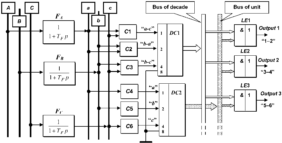
Fig. 1. Block diagram of the adaptive comparator interval-code SU with tracing fixation of self-switching points of mains voltage
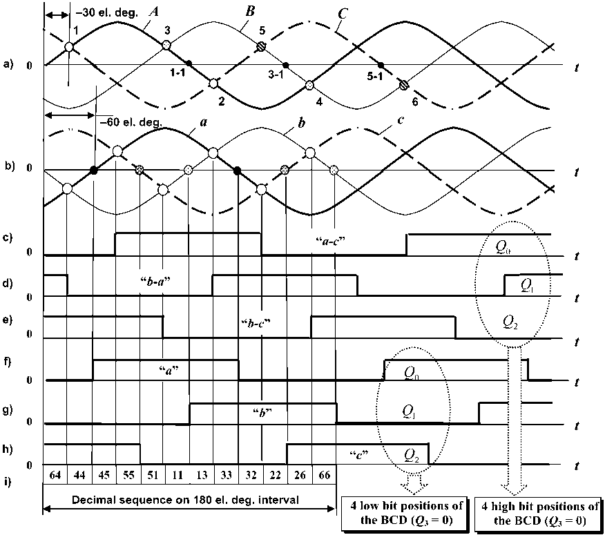
Fig. 2. Time diagram of the signals (a–h) and table of sequence of decimal numbers (i) of the adaptive comparator interval-code SU with tracing fixation of self-switching points of mains voltage of A, B, C voltages is characterized by its own BCD (or by a decimal number), the general sequence of which in the 180 electrical degrees interval has a form “64–44–45–55–51–11–13–33–32–22–26–66” (fig. 2, i).
With the help of output units LE 1– LE 3, therefore, the signal “1” can be differentiated, the width of which will correspond to the required control interval of power inverters SC.
For example, for a three-phase “zero” controlled rectifier (fig. 2, a):
|
Interval “1”–“1-1” |
Interval “3”–“3-1” |
Interval “5”–“5-1” |
|
44 45 55 51 11 |
11 13 33 32 22 |
22 26 66 64 44 |
For a three-phase bridge controlled rectifier:
|
Interval “1”–“2” |
Interval “3”–“4” |
Interval “5”–“6” |
|
44 45 55 51 11 13 |
11 13 33 32 22 26 |
22 26 66 64 44 45 |
Besides, for control systems of DC drive with indirect exitation, for example, such SU can be used as the main synchronization channel, which forms simultaneously synchronization signals for the three-phase rectifier which supplies motor armature and the one-phase rectifier which supplies excitation winding. In this case there only additional units “AND–OR” will be included to the block-diagram of the SU (fig. 1), which provide differentiation of the required synchronization intervals for the second SC.
Together with this, both symmetric and asymmetric amplitude change of phase voltages does not bring a mistake to the synchronization process, because the SU makes pairwise (tracing) fixation of self-switching points of the signals “a”, “b”, “c” and time of their crossing the zero level (fig. 2, b).
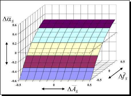
Fig. 3. The characteristic Δα S = f ( А S , Δ f S ) of the adaptive comparator interval-code SU with tracing fixation of self-switching points of mains voltage
The characteristic Δα S = f ( АS , Δ fS ) is given in fig. 3, which has been derived by means of simulation of the SU in software suite Matlab+Simulink , which shows that deviation of the synchronization process does not depend on signal amplitude of synchronization and is defined only by mains voltage frequency, that is why filters FA , FB , FC are used. Here
Δα S = ( α∗ S / α S ) - 1 – the standardized value of the actual synchronization angle α∗ S relative to the given α S = 30 electrical degrees; АS = АS ∗ / АS – the standardized amplitude of the synchronization signal АS ∗ (of mains voltage) relative to its rated value АS ; Δ fS = ( fS ∗ / fS ) - 1 – the standardized fault fS ∗ of power line frequency relative to its rated value fS .
2. The integrating interval-code synchronizing unit
In the systems with an abnormally distorted power line, for example, on objects with autonomicbased power systems it is recommended to use the SU based on principle of integrating sweeping conversion [7, 11–14]. Let us consider the above-mentioned variant of SU design applying to a three-phase bridge rectifier, for example, with a separate control [6, 15].
The basis of SU (fig. 4) are three [7, 16–17] identical integrating sweep converters ISCA , ISCB , ISCC . They consist of (fig. 4) adder Σ , integrator I with time constant T and relay element RE with a noninverting hysteresis loop. The output signal of RE changes discretely within limits ± A .
ISCA , ISCB , ISCC are present self-oscillating systems with frequency-pulse-width modulation [18–21] in initial state, where the output signal amplitude of the integrator I is limited by switching thresholds of RE and the signal has a sawtooth waveform. The inverting element IN is included to the diagram in order to correlate the outputs ISCA , ISCB , ISCC with further digital elements.
When AC voltage of the power line goes to an input, for example ISC A , and its amplitude outgoes the one of the output pulses of the RE in 2,0–4,0 times, the ISC switches to external synchronization mode, when the frequency of its output pulses is equal to the one of mains voltage. If the frequency of ISCA ’s selfoscillations has been chosen to be equal to the one of mains voltage, then a phase-shift between the synchronization signal and the output pulses of the RE (of inverting element IN ) becomes equal to minus 90 electrical degrees (fig. 5, a–d) [14, 16], and the ISC itself gets the properties of the first-order aperiodic filter [6–7]
W ( p ) =
1 + ТEр
with time constant
Т ≈πТА E SS where АS = АS /А is a relative value of the ampli- tude АS of mains voltage with the period TS .
So, the ISC in the external synchronization mode gets the properties of the filter, time constant of which automatically turns into the functions of mains voltage
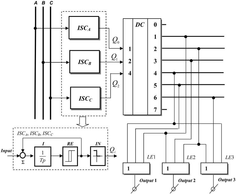
Fig. 4. Block diagram of the adaptive integrating interval-code synchronizing unit
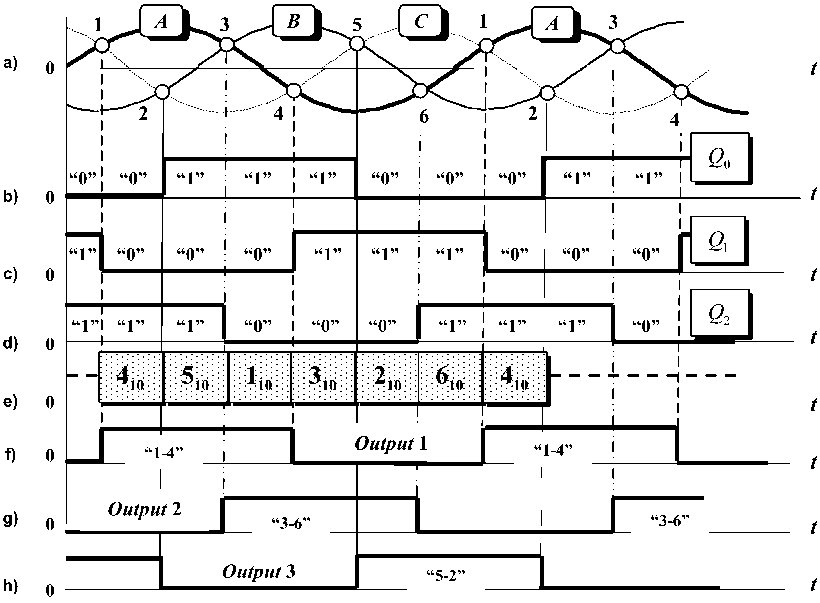
Fig. 5. Time diagrams of signals of the adaptive integrating interval-code synchronizing unit parameters. It is worth taking into account that in comparison with the filters FA, FB, FC (fig. 1) the ISC represents a closed system with an integrator in the direct channel of control that contributes to stability of time and temperature characteristics of synchronization channels [22].
Hereinafter we consider that ISCA forms the signal Q 0 of the low bit-position and ISCC – the signal Q 2 of the high bit position of the binary code (fig. 5, b–d) which go to the decoder DC (fig. 4).
Then to each of the sections “1–2”, “2–3”, “3–4”, “4–5” and “5–6” of the three-phase voltage system (fig. 5, a) its own decimal number from the set “4–5– 1–3–2” will correspond.
Combining the corresponding numbers by the function “OR” with the help of the logical elements LE 1– LE 3 the pulses of the logical “1” will be formed on the output of the SU (fig. 5, f–h), the width of which corresponds to the intervals “1–4”, “3–6” and “5–2” of self-switching points of the phases A , B , C in limits of which the control angle of thyristors in the bridge controlled rectifier is regulated.
The characteristic Δ α S = f ( АS , Δ fS ) for the SU with the ISC is practically similar to the one given in fig. 3. In this case during variations of synchronization voltage amplitude (of the power line) the integrator I aims at retaining average value of output pulses to be equal to zero, and as a result compensation of synchronization fault occurs.
Findings
-
1. The SU with tracing fixation of self-switching points of mains voltage is introduced, where with the help of first-order aperiodic filters the auxiliary three-phase voltage system is generated, which is shifted relative to the main on minus 60 electrical degrees. As a result of pairwise comparison of mains voltages with the help of the comparators the number series is gained, from which the synchronization signal for the needed power diagram of the SC can be derived selectively. For the power line with the low level of interference time constant of smoothing filters can be chosen at the level of minus 30 electrical degrees.
-
2. High sensitivity of the comparator SU towards external interference and the open-circuited structure of the input filters that has a negative impact on the metrological characteristics of the synchronization channels can be considered as drawbacks of the comparing SU.
-
3. The integrating interval-code SU is considered, which is realized at the basis of the ISC s working in external synchronization mode with mains voltage frequency. In this case the synchronization channels get the properties of the adaptive first-order aperiodic filters with time constant determined by the mains voltage parameters. The recommendations concerning the choice of the synchronization conditions are given.
-
4. The integrating interval-code SU have higher metrological characteristics because of their closed-
- circuited structure and the presence of the integrator in the direct channel of control.
-
5. The introduced SU can be recommended for the power SC working with the power systems which have significant instability of the amplitude of mains voltage.
References Adaptive interval-code synchronizing units
- Жежеленко, И.В. Качество электроэнергии на промышленных предприятиях/И.В. Жежеленко, М.Л. Рабинович, В.М. Божко. -Киев: Технiка, 1981. -160 с.
- ГОСТ 32144-2013. Электрическая энергия. Совместимость технических средств электромагнитная. Норма качества электрической энергии в системах электроснабжения общего назначения. -М.: Cтандартинформ, 2014. -16 с.
- Хабигер, Э. Электромагнитная совместимость. Основы ее обеспечения в технике/Э. Хабигер. -М.: Энергоатомиздат, 1995. -304 с.
- Иванов, А.Г. Системы управления полупроводниковыми преобразователями/А.Г. Иванов, Г.А. Белов, А.Г. Сергеев. -Чебоксары: Изд-во Чуваш. ун-та, 2010. -448 с.
- Чернов, Е.А. Комплектные электроприводы станков с ЧПУ: справ. пособие/Е.А. Чернов, В.П. Кузьмин. -Горький: Волго-Вятское кн. изд-во, 1989. -320 с.
- Дудкин М.М., Цытович Л.И. Элементы информационной электроники систем управления вентильными преобразователями: моногр. -Челябинск: Издат. центр ЮУрГУ, 2011. -362 с.
- Качалов, А.В. Интегрирующие устройства синхронизации для систем импульсно-фазового управления вентильными преобразователями/А.В. Качалов, Л.И. Цытович, М.М. Дудкин//Практическая силовая электроника. -2010. -№ 1 (37). -С. 42-51.
- Пат. 2400911 Российская Федерация, МПК7 Н 02 М 1/08. Устройство синхронизации/Л.И. Цытович, М.М. Дудкин, А.В. Качалов, Р.М. Рахматулин. -№ 2009113987/09; заявл. 13.04.09; опубл. 27.09.10, Бюл. № 27.
- Adaptive interval and code bidecimal timing mechanism with watching fixing of points of natural commutation of circuit voltage/L.I. Tsytovich, M.M. Dudkin, O.G. Brylina, A.V. Tugaev//Materials of the III international research and practice conference “European Science and Technology”. -Munich -Germany: Publishing office Vela Verlag Waldkraiburg, 2012. -Vol. I. -October 30th-31st. -PP. 276-281.
- Interval coders of synchronization for controlling systems of power valve inverter/L.I. Tsytovich, M.M. Dudkin, O.G. Brylina, A.V. Tugaev//Materials of the international research and practice conference “Science, Technology and Higher Education”. -Westwood -Canada: Publishing office Accent Graphics communications, 2012. -Vol. II. -December 11th-12th. -PP. 541-558.
- Пат. 2513024 Российская Федерация, МПК7 Н 02 М 1/00. Адаптивное интегрирующее устройство синхронизации/М.М. Дудкин. -№ 2012128705/07; заявл. 09.07.12; опубл. 20.01.14, Бюл. № 2.
- Адаптивная интервало-кодовая двоично-десятичная интегрирующая синхронизация систем управления силовыми вентильными преобразователями/Л.И. Цытович, О.Г. Брылина, М.М. Дудкин, Р.М. Рахматулин//Электротехника. -2013. -№ 3. -С. 8-15.
- Интегрирующие интервалокодовые устройства синхронизации для ведомых сетью вентильных преобразователей/Л.И. Цытович, М.М. Дудкин, О.Г. Брылина, А.В. Тюгаев//Практическая силовая электроника. -2013. -№ 4 (52). -С. 20-27.
- Интегрирующее устройство синхронизации с псевдоследящей фиксацией точек естественной коммутации напряжения сети/Л.И. Цытович, М.М. Дудкин, О.Г. Брылина, А.В. Тюгаев//Вестник ЮУрГУ. Серия «Энергетика». -2013. -Т. 13, № 2. -С. 53-61.
- Реверсивный тиристорный преобразователь для систем управления с питанием от сети с нестационарными параметрами/Л.И. Цытович, Р.М. Рахматулин, М.М. Дудкин, А.В. Качалов//Практическая силовая электроника. -2009. -№ 2 (34). -С. 35-41.
- Пат. 2461948 Российская Федерация. МПК7 Н 02 М 1/08. Устройство синхронизации/Л.И. Цытович, М.М. Дудкин, А.В. Качалов, О.Г. Брылина, Р.М. Рахматуллин. -№ 2011117488/07; заявл. 29.04.11; опубл. 20.09.12, Бюл. № 26.
- Помехоустойчивая интегрирующая синхронизация ведомых сетью вентильных преобразователей/Л.И. Цытович, М.М. Дудкин, Р.М. Рахматулин и др.//Энергетик. -2014. -№ 6. -С. 15-18.
- Дудкин, М.М. Динамические характеристики развертывающего преобразователя с частотно-широтно-импульсной модуляцией/М.М. Дудкин, О.Г. Брылина, Л.И. Цытович//Вестник ЮУрГУ. Серия «Энергетика». -2014. -Т. 14, № 3. -С. 46-54.
- Дудкин, М.М. Спектральные характеристики развертывающих преобразователей с широтно-импульсной и частотно-широтно-импульсной модуляцией/М.М. Дудкин, Л.И. Цытович, О.Г. Брылина//Электротехника. -2013. -№ 10. -С. 18-25.
- Дудкин, М.М. Спектральные характеристики развертывающего преобразователя с частотно-широтно-импульсной модуляцией/М.М. Дудкин, Л.И. Цытович, О.Г. Брылина//Практическая силовая электроника. -2014. -№ 1 (53). -С. 17-20.
- Частотно-широтно-импульсный адаптивный регулятор переменного напряжения с интегрирующей системой управления/М.М. Дудкин, О.Г. Брылина, Л.И. Цытович, А.В. Тюгаев//Вестник ЮУрГУ. Серия «Энергетика». -2013. -Т. 13, № 2. -С. 45-52.
- Дудкин, М.М. Интегрирующие фазосдвигающие устройства для управления силовыми вентильными преобразователями: дис. … канд. техн. наук/М.М. Дудкин. -Челябинск: ЮУрГУ, 2007. -235 c.
