ADPCM Image Compression Techniques for Remote Sensing Applications

Author: Ashok Kumar, Rajiv Kumaran, Sandip Paul, Sanjeev Mehta
Journal: International Journal of Information Engineering and Electronic Business(IJIEEB) @ijieeb
Article in issue: 3 vol.7, 2015.
Free access
ISRO's remote sensing continuity mission Resourcesat-II provided better radiometric performance as compared to Resourcesat-I. However, this improvement required implementation of onboard image compression techniques to maintain same transmission interface. In LISS-4 payload, prediction based DPCM technique with 10:7 compression ratio was implemented. Based on received data from this payload, some ringing artifacts were reported at high contrast targets, which degrade image quality significantly. However occurrences of such instances were very few. For future missions, efforts are made to develop an improved low complex image compression technique with better radiometry and lesser artifacts. Adaptive DPCM (ADPCM) technique provides better radiometric performance. This technique has been implemented onboard by other space agencies with their own proprietary algorithm. To maintain existing 10:7 compression ratio, novel ADPCM techniques with adaptive quantizers are developed. Developed ADPCM techniques are unique w.r.t. predictor and encoding. Developed techniques improve RMSE from 1.3 to 10 times depending on image contrast. Ringing artifacts are reduced to 1% from 38% with previous technique. Developed techniques are of low complexity and can be implemented in low end FPGA.
DPCM, RMSE, Dynamic Range, Compression
Short address: https://sciup.org/15013345
IDR: 15013345
Text of the scientific article ADPCM Image Compression Techniques for Remote Sensing Applications
Published Online May 2015 in MECS
Due to recent advancement in sensor technology, ISRO’s future remote sensing systems will have better spatial, radiometric, and spectral resolution. This improvement leads to higher data volume. Image compression is usually employed to meet transmission capability in space missions [1]. Compression ratio is usually decided by trade-off studies between available satellite resources and image quality requirement from user community.
DPCM, a prediction based image data compression techniques, has been used in many missions. Table-1 provides usage summary for DPCM and its adaptive part ADPCM [1].
Table 1. Usage of DPCM technique onboard
|
Satellite |
Compressio n Algorithm |
Compression Ratio |
Implem entation |
|
|
SPOT-I/II/III/IV (CNES1986/90/93/9 8) |
Fixed Rate DPCM |
8:6 |
1.33 |
- |
|
Resourcesat-II (ISRO 2011) |
10:7 |
1.41 |
FPGA |
|
|
LANDSAT-7 (M7) |
ADPCM Kodak |
8:1.5 |
2.5,5 |
- |
|
IKONOS (US GeoEye1999) |
11:2.5 |
4.4 |
ASIC Kodak |
|
|
QuickBird (US DigitalGlobe 2001) |
11:X |
- |
||
|
WorldView-1 (US DigitalGlobe2007) |
11:4 |
2.75, 4.3 |
ASIC Kodak |
|
|
Chang’E-1 (China2007) |
Differential Predictive (DPCM) |
- |
2 |
FPGA |
In Resourcesat-2 (ISRO-2011) LISS-4 payload, DPCM technique was used with compression ratio of 10:7 [2]. This availability of 10-bit radiometric data leads to better image quality as compared to Resourcesat-1 (7-bit digitization) [3, 4]. Fig. 1 shows few onboard images (False Color image after fusion of multi-spectral data).
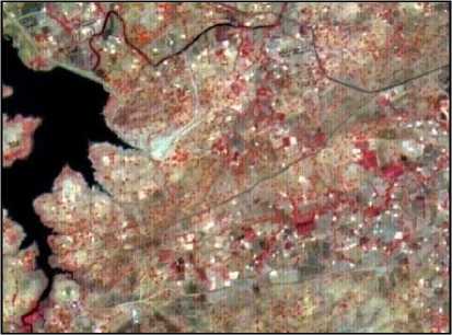
Fig. 2 shows typical histogram of an LISS-4 image (12000X12000). Kindly observe the non-linear axis.
Fig. 1. Resourcesat-2 LISS-4 images
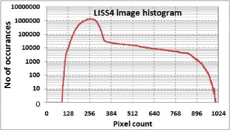
Fig. 2. Histogram of LISS-4 data
Implemented DPCM technique has quantizer dynamic range of 270 pixel difference counts, which was derived based on analysis of various payload images. But, difference count up to 600 was observed due to higher system MTF performance, which indicates that ringing artifacts are expected at high contrast locations [3]. Higher dynamic range of quantizer may force radiometric degradation at lower contrast locations. Existing technique also causes error propagation in recovery of 25% pixels [3].
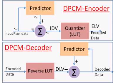
Fig. 3. Existing DPCM block diagram
II. Exisiting DPCM Technique in LISS-4 Payload
Block diagram of existing DPCM encoder/decoder [24] is shown in Fig. 3. DPCM is implemented in a group of pixels. In a single group, at least one pixel is transmitted in its original form (lossless). For remaining pixels, residue with predictor is quantized and transmitted [5].
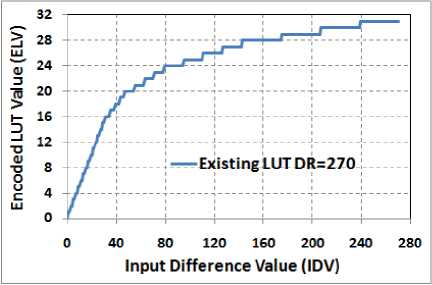
Fig. 4. Existing DPCM’s Quantizer (LUT)
Table 2: Algorithm of Existing DPCM Technique
|
DPCM operation for Odd Pixel Group |
||||
|
Input odd port data |
P1 (10-bit) |
P3 (10-bit) |
P5 (10-bit) |
P7 (10-bit) |
|
DPCM Operation |
P1 – P3 |
Ref Pixel |
P3 – P5 |
P5 – P7 |
|
Output bits after LUT mapping & adding sign bit |
6-bit |
Original (Lossless) 10-bit |
6-bit |
6-bit |
|
DPCM operation for Even Pixel Group |
||||
|
Input even port data |
P2 (10-bit) |
P4 (10-bit) |
P6 (10-bit) |
P8 (10-bit) |
|
DPCM Operation |
P2 – P4 |
P4– P6 |
Ref Pixel |
P6 – P8 |
|
Output bits after LUT mapping & adding sign bit |
6-bit |
6-bit |
Original (Lossles s) 10-bit |
6-bit |
Input Difference Value (IDV) i.e. the DPCM residue P1-P3 or similar is quantized through LUT and 6-bit (including one sign bit) Encoded LUT value (ELV) is generated. One of the pixels is sent without processing. Hence 25% data will be recovered losslessly.
Existing DPCM technique is developed with quantizer dynamic range of 270 IDV only, which was derived based on analysis of various payload images. But, IDV up to 600 count is possible due to higher system MTF performance, which indicates that ringing artifacts are expected at high contrast locations [3]. Dynamic range of existing LUT can be increased through bigger quantization step sizes, but this will degrade radiometric performance. Another issue with existing DPCM technique is error propagation i.e. error in recovery of P5 pixel affects P7 pixel’s recovery.
The issue of dynamic range coverage and radiometric performance can be resolved by multiple quantizers. Quantizers will be applied selectively as per input contrast per group. Quantizer with small step size will be applied at low contrast location; this will ensure better radiometric performance considering higher probability of such instances (60-90%). Quantizer with bigger step size will be applied at high contrast location. This will cover input dynamic range and reduce ringing artifacts. Requirement of multiple quantizers leads to Adaptive DPCM (ADPCM) technique, which is discussed in next section.
-
III. Development of ADPCM Techniques for LISS-4 Payload data configuration
Because of lower complexity, ADPCM with adaptive quantizer is considered for development [5]. In single ADPCM group, one pixel is transmitted in original form (lossless) [5]. For remaining pixels, residue i.e. difference with predictor is quantized by look up table (LUT). Fig. 5 shows block diagram of ADPCM technique.
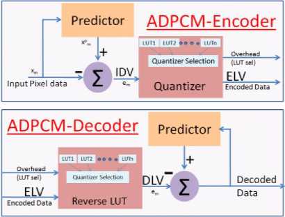
Fig. 5. ADPCM block diagram
-
A. Development of ADPCM-4P technique
ADPCM-4P technique requires compression of 4-pixel 40-bit data to 28-bit. One reference pixel will occupy full 10-bits. Three input difference values (IDV) i.e. DPCM residue are quantized through selected LUT. This generates three 6-bit (including sign bit) encoded LUT values (ELV). Hence, no spare bit is available to indicate used LUT in ADPCM. Requirement of 3 sign bit transmission can be omitted if all IDVs are positive. This is possible by selecting the pixel with smallest value as a predictor for remaining three pixels. But, predictor location information has to be transmitted along the encoded data which will require additional 2-bits. The remaining 1-bit can be used for LUT selection. Encoding of proposed ADPCM-4P technique for an odd pixel group is shown in Table 3 with all four combinations.
Table 3. Encoding of Proposed ADPCM-4P
|
REF Pixel |
ODD Pixels |
P1 (10-bit |
P3 (10-bit) |
P5 (10-bit) |
P7 (10-bit |
REF index |
SEL LUT |
|
P1 |
й .о 2 55 Он о 3 и Q |
P1 (10-bit) |
P3-REF (5-bit) |
P5-REF (5-bit) |
P7-REF (5-bit) |
00 (2-bit) |
СО '^ |
|
P3 |
P1-REF (5-bit) |
P3 (10-bit) |
P5-REF (5-bit) |
P7-REF (5-bit) |
01 (2-bit) |
||
|
P5 |
P1-REF (5-bit) |
P3-REF (5-bit) |
P5 (10-bit) |
P7-REF (5-bit) |
10 (2-bit) |
||
|
P7 |
P1-REF (5-bit) |
P3-REF (5-bit) |
P5-REF (5-bit) |
P7 (10-bit) |
11 (2-bit) |
For low contrast group, lossless LUT (LUT-DR-31) is applied. This means IDV values are transmitted without any losses. For high contrast group, lossy piecewise linear LUT (LUT-DR-600) is applied. LUT-DR-600 will cover full input dynamic range and helps in avoiding ringing artifacts. Fig. 6 shows details of both these LUTs. Proposed LUTs commensurate with expected IDV histogram, shown in Fig. 7. Kindly observe non-linear axis in plot.
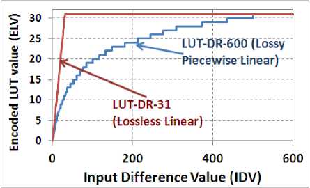
Fig. 6. Proposed ADPCM’s Quantizer Details
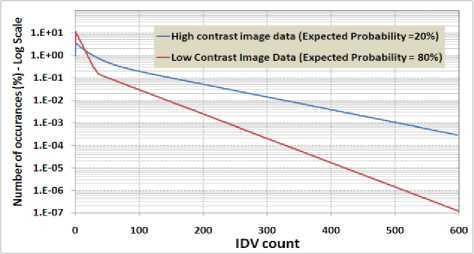
Fig. 7. Histogram of expected IDV counts
m — 1 n — 1
RMSE = - ZZ I ref ( (, j ) 1 re cov ered (i, j)]2
m.n ( = 0 j = o
where [m n] is image size. I REF is considered reference image-set for simulation purpose, while I recovered is decompressed image.
Entropy ( bits / pixel ) = log 2
Z ( . p ( ( )
. ( = 0
p ( ( ) = probabiliyof ( th count
One of the main advantages of this technique is zero error propagation. However, this leads to poor prediction because reference pixel can be one of the four pixels. If it is P1 or P7, then poor correlation may increase residues and then quantization errors. Requirement of pixel sorting slightly increases hardware implementation complexity.
-
B. Development of ADPCM-5P technique
Algorithm of proposed ADPCM-5P technique for an odd pixel group is shown in Table 4. A group of 5 adjacent pixels is processed at a time. Details of required quantizers are already mentioned in Fig. 6.
Table 4. Algorithm of Proposed ADPCM-5P
|
Odd Pixels |
P1 (10-bit) |
P3 (10-bit) |
P5 (10-bit) |
P7 (10-bit) |
P9 (10-bit) |
SEL LUT |
|
DPCM Operation |
P1-P3 (6-bit) |
P3-P5 (6-bit) |
REF= P5 (10-bit) |
P5-P7 (6-bit) |
P7-P9 (6-bit) |
S (1-bit) |
∆E P3 = DLV (ELV(IDV P1-P3 )) – IDV P1-P3 (1)
∆E P7 = DLV (ELV(IDV P7-P9 )) – IDV P7-P9 (2)
Rather than quantizing P1-P3 & P7-P9 data, P1-P3+∆E P3 & P7-P9-∆E P7 will be quantized respectively. This technique is termed as ADPCM-5P-NEP (no error propagation).
-
IV. RMSE Simulation Results
Line Complexity =
| m n — 1
- ZZIIref (i, J + 1) — Iecovered (i, J)| m (n -1) i=0 J=0
Line complexity is computed from across track odd pixel data.
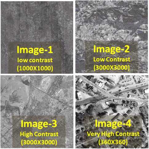
Fig. 8. Image-sets used for simulation
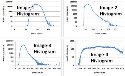
Fig. 9. Histogram of simulation image-sets
Table 5: Simulation Image-sets parameters
|
Mean |
Std. |
Max D)V |
IDA" Entropy |
Complexity |
|
|
Imagel (1000X1000) |
97.4 |
11.9 |
71 |
3.4 |
8.1 |
|
Image! (3000X3000) |
60.1 |
12.4 |
182 |
2.5 |
43 |
|
Image3 (3000X3000) |
184.6 |
32.5 |
799 |
3.9 |
13 |
|
Imagel (360X360) |
553.5 |
221.1 |
794 |
6.5 |
95.8 |
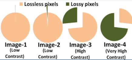
Fig. 13. Recovered data statistics with ADPCM-4P
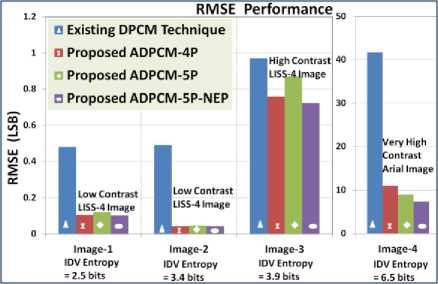
Fig. 10. RMSE performance comparison
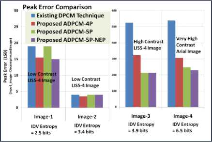
Fig. 11. Peak Error Performance Comparison
Lossless pixels ■ Lossy pixels

Image-1 Image-2 Image-3 Image-4
(Low (Low (High (Very High
Contrast)Contrast)Contrast)Contrast)
Fig. 12. Recovered data statistics with ADPCM-5P
-
V. Ringing Artifacts Simulation Results
12 pixel one dimensional worst case simulation dataset is developed as per system MTF. In uniform regions, ringing artifacts are computed by using Equation 6. Fig. 14 shows simulation results. Proposed ADPCM technique reduce ringing artifacts to <1.5%.
RingingArtifacts ( RA %)
p ( P n -1 + P n +1)
P n -2 *100
( P n -1 + P n +1)
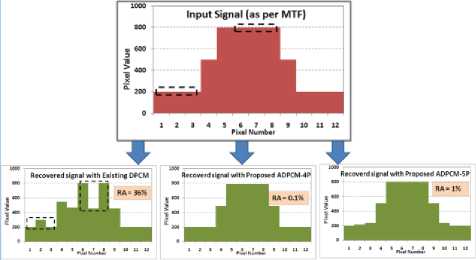
Fig. 14. Ringing artifact simulation with 12-pixel one dimensional data
Simulation dataset (8X8 pixel matrix) with maximum contrast is developed as per LISS-4 system MTF [3]. Fig. 15 shows simulation results (color mapped). In uniform along track and across track regions, ringing artifacts are computed by using Equation 6. Proposed ADPCM techniques reduce ringing artifacts to <1.5%.
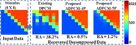
Fig. 15. Ringing Artifacts Simulation with 8X8 matrix (2-D dataset)
In recovered image 1 to 4 [Fig. 8], no visual ringing artifacts were observed. For visual analysis, some artificial high intensity objects were inserted in image-4. Recovered images are shown in Fig. 16. It can be concluded that ADPCM reduces ringing artifacts significantly.
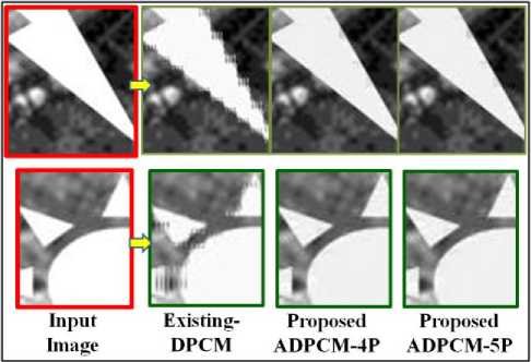
Fig. 16. Ringing Artifacts simulation results on image-4
From above analysis, it can be noted that ringing artifacts cannot be eliminated fully, as these arise because of quantization. Artifact pattern and its extent depend on encoding technique and quantization table. Other space agencies have also reported DPCM noise in recovered image. Fig. 17 shows noise due to ADPCM compression, reported for IKONOS PAN images [7, 8].
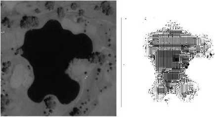
lake in Reid Park, Tucson
DM 200-220 contrast-stretched
Fig. 17. DPCM noise observed in IKONOS PAN Image
-
VI. Conclusion
The proposed novel ADPCM techniques shows better image reproducibility compared to existing DPCM technique. New ADPCM techniques maintain the compression ratio of 10:7 and achieve significant radiometric improvement on low as well as high contrast images compared to existing DPCM technique. Developed ADPCM techniques produce RMSE of 10 counts compared to 41 counts for very high contrast image. These produces RMSE of 0.04 counts compared to 0.48 counts with low contrast images. Ringing artifacts are reduced to 0.5% compared to 38.2%. Algorithm of both techniques has low complexity.
Acknowledgment
We gratefully acknowledge the constant encouragement and guidance received from Shri Arup Roy Chowdhury – GD-SEG, Shri R M Parmar-DD-SRA, Shri DRM Samudraiah- Prof. Satish Dhawan Scientist, Shri Saji A Kuriakose–DD-SEDA and Shri A. S. Kiran Kumar-Director SAC. We are thankful to our colleagues of Payload Checkout Electronics Group for providing the images.
References ADPCM Image Compression Techniques for Remote Sensing Applications
- Guoxia Yu, Tanya Vladimirova: 'Image Compression systems on board satellites', Acta Astronautica, vol 64, pp 988-1005, 2009.
- Deviprasad: "Indian Remote Sensing Satellites- Resourcesat2 Mission Status', India Civil Commercial Imagery Evaluation Workshop, March 17, 2010.
- Ashok Kumar, Rajiv Kumaran: 'Improvement in DPCM image Compression Technique', International Conference on Information Technology in Signal and Image Processing (itSIP)-2013, 18-19 Oct-2013, Mumbai-India, pp 280-284.
- Ashok Kumar, Rajiv Kumaran: 'A low complex ADPCM image compression technique with higher compression ratio', International Journal of Computer Engineering and Technology, Vol 4 Issue 6, Nov-Dec (2013), pp 367-377.
- Majid Rabbani: 'Digital Image Compression Techniques', Eastman Kodak Company, Volume TT 7, Spie Optical Engineering Press, 1995.
- Rafel C Gonzalez, "Digital Image Processing using MATLAB".
- Bernd Girod, "EE398B – Image Communication II", a presentation data.
- Robert A. Schowengerdt "ECE/OPTI533 Digital Image Processing class notes", a presentation data.
