Advanced control of switching ignition by smart helmet

Author: Seelam Vasavi Sai Viswanada Prabhu Deva Kumar, Shyam Akashe, Vikram Kumar
Journal: International Journal of Image, Graphics and Signal Processing @ijigsp
Article in issue: 2 vol.10, 2018.
Free access
The impact of Accident effect, a lot of human livelihoods and their career, due to the negligence of wearing the helmets on a daily basis in India. To end this suffering, we have a social responsibility development projects. The motorcycle driver without wearing the helmet can be killed if it hit or crash and bring his life in danger. Wearing a helmet reduces the possibility of danger of life. In India, for example, wearing a helmet is mandatory in the law and the drivers need to follow it. Similar rules are in many countries. Therefore, this project is designed to improve motorcycle safety and make motorcyclist compulsory for wearing it. As you can see, we have a lot to think about it. It is a type that is used in the driver's helmet to drive a bike safely. The aim of this paper is to protect the driver life and decrease the death rate at road accident by making the helmet. It uses a hands-free kit and advances feature like compulsory of wearing helmet and theft security. Bluetooth wireless communication module (2.4 GHz band transceiver) can be used for transmission between the transmitter and the receiver. The driver needs to wear a helmet otherwise a helmet automatically keeps the engine OFF. If rider wears the helmet, ignition will be automatically ON. In the sensor, we transmit information to the wireless communication module, which is connected to the bike. This system is one of the devices built in the helmet; the second devices are inside the bike. Monitor recognizes the power devices with a Force-sensing resistor (FSR). Wireless data receiver, encoder, and a transmitter are used to communicate helmet with the bike. AT mega controller in both devices used as a CPU. It is one of the most advanced electronic projects for the Road Safety Systems.
Driver Safety, Smart Helmet, Atmega Controllers, Force sensing resistor (FSR), Embedded C, USART Communication, 7805IC
Short address: https://sciup.org/15015938
IDR: 15015938 | DOI: 10.5815/ijigsp.2018.02.04
Text of the scientific article Advanced control of switching ignition by smart helmet
Published Online February 2018 in MECS
Tools —CodeVisionAVR, PCB Wizard
Programmer —USBasp
-
I. Introduction
Road accident had become one of the major topics of discussion for the whole world. After repeated awareness campaign organized by government authority regarding the importance of helmet for road safety, peoples are paying no heed to it. Most motorcyclists’ death is due to head injuries. In India, 78% of road vehicles are two-wheelers. 29% of total road accidents are of two-wheelers. It is statistically increasing from 26.3% in 2013 to 27.3% in 2014 and 28.8% in 2015. So, it has become one of the most secure modes of transport nowadays. The UN study tells, “Motorcyclists are 26 times more likely to die in a road crash than drivers of passenger cars”. Wearing a proper helmet improves their probability of endurance by 42% and helps to avoid 69% of injuries to riders.
A motorcyclist’s helmet, also called safety helmet, acts as a protective headgear because it prevents from any fatal head injury. So, every government has some laws to enforce it to their city for making it compulsory to wear. In India, the Sections 128 and 129 of the Motor Vehicles (MV) Act, 1988, made the wearing of helmets by twowheeler users mandatory.
The main objective of this project is to make motorcyclist user wear the helmet. Either way, it is necessary to wear it, too on the ignition of the engine. In case, if the driver is not in a position to wear the helmet then the driver doesn’t have a right to drive the vehicle. This will also keep the vehicle secure from any theft. The helmet which we have proposed is made from the combination of Transmitter and the Receiver section. The Transmitter portion is embedded with a sensor, Bluetooth module and controller. The Receiver portion is embedded with Bluetooth module, controller, status display and relay. The Controller is used in this project to control the whole operation. The ignition of the motorcycle can start only if the users wear the helmet properly.
-
II. 8-Bit Microcontroller
In this project, we use two controllers ATMEGA16L and ATMEGA8A is an 8-bit microcontroller designed to support low power CMOS technology for better structural design RISC AVR 32 * 8 High-Performance Registry Features. Manufactured by Atmel with Drive Unit Nonvolatile storage is very compact. The on-chip system memory 16 KB Flash memory program EEPROM 512 Kb and 1 Kb SRAM internal memory. This ATMEGA16L microcontroller has a 40-pin, programmable 32-pin line input (4 ports each port 8) and ATMEGA8A has 28 pin, 24-pin programmable input lines (3 ports per PIN of port 8) has pulse modulation Four channels, eight ADC channels with 10-bit input terminal 3 are used for DC (5V), two pins are used for the 3-pin AREF, AVCC and RESET crystal oscillator (XTAL2, XTAL1). This microcontroller operates at 2.7V - 5.5V from the 0.35mA - 1.1mA power in idle mode with the 0 - 8 MHz level. Boot loader software continues to work while the flash is updated application area to read correctly during the registration. The combination of 8 bits of automatic flash chip system processor RISC programmable monolithic machines. These are most commonly used microcontroller is a convenient and easy to implement the integrated application. It supports Embedded C and Assembler language of the coding system.
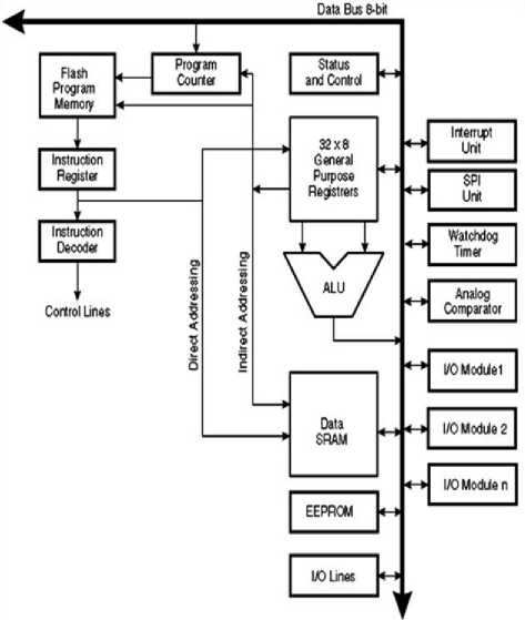
Fig.1.General Architecture of ATMEL microcontroller
-
III. Bluetooth Module
HC-05 Bluetooth module is an easy-to-use (SPP) Serial Port Protocol module. It is considered for transparent wireless serial communication. HC-05 Bluetooth module can be used in master or slave configurations, building it an excellent resolution for wireless communication. Bluetooth V2.0 + EDR 3Mbps is complete Advanced Data Bluetooth Rate 2.4 GHz module and total bandwidth. The CSR Blue Core Bluetooth 04 uses the system with a single external CMOS chip technology, and (Depending on the adaptive frequency jumper frequency) AFH.
Bluetooth module HC-05 is a master/slave drive. By default, the module is set in SLAVE mode. Function modules (master or slave) can only configure AT commands. Slave units cannot establish a connection with an additional device, Bluetooth, but it can recognize associates connections. The master module can start a connection to other devices. You can only use it for a serial port replacement to establish a connection between MCUs and GPS, PCs to the implementation project, etc.
Hardware features:
-
• Typical -80 dBm sensitivity.
-
• Power transmission at up to +4 dBm.
-
• Input/output voltage is 3.3-5volts.
-
• IOP control (programmable input / output).
-
• UART interface with programmable baud rate.
-
• Built-in antenna included.
Software features:
-
• Standard slave transmission speed: 9600, 8 data bits, 01 stop bits, no parity.
-
• Power turns on automatically by default and connects to the last device.
-
• Pairing allow you to connect standard devices.
-
• PIN code auto sync: "1234", by default.
-
(A) Enable:
If the enable is low, means that the module that it is not communicating with the device is not turned off. While the enable is opened, or when connected to 3.3 V, it is activated, the module enters, it remains in communication.
-
(B) Vcc:
Voltage source is +3.3V to +5V
-
(C) GND:
Voltage source is -3.3V to -5V
-
(D) Txd and Rxd:
These two pins, acts as an interface of UART communication
-
(E) State:
It acts as a status indicator. Modules, other devices, though not in combination with a low-level signal. The low state indicates that the LED flash continuously, the module is not connected to another device. To another device, signal active state High. At, LED indicates that the device is configured to flash over a fixed delay 2c in the delay example.
-
(F) Button Switch:
It is used to change the module in the AT command mode. , To start the power button to run second. With using the AT command mode, a user can modify the parameters of this module, only when BT device is not paired with other. When connected to all Bluetooth devices, and to start communication with the device, does not work with the AT command mode.
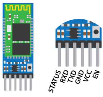
Fig.2. Bluetooth Module
-
IV. Force Sensing Resistor (FSR)
It is a force sensitive resistor with a square detection surface of 1.75 x 1.5", which varies the resistance to the pressure that is exerted on the detection zone. FSR is basically a resistance that changes the resistance value (in ohms); depending on how much the pressure resistance applies. The FSR will be 1MΩ higher resistance. FSRs can be anywhere in the range of 100g to 10kg. These sensors are easy to install and are ideal for pressure measurement, but they are not very accurate. Use it to detect if it is pressed, but you cannot decide to use it as a staircase.
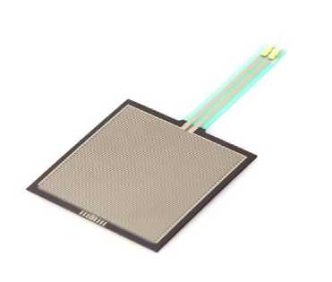
Fig.3. Force Sensing Resistor
FSR features (Force Sensing Resistor) has the following drawback that are linear. The following table is a logarithmic curve. And it is not a linear feature.
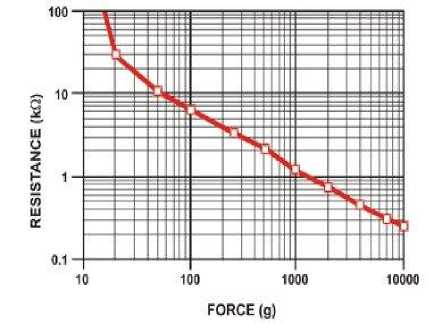
Fig.4. Force Vs Resistance
The following graph of force and conductance,
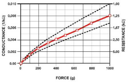
Fig.5. Conductance Vs Force(0-1Kg)Low Force Range
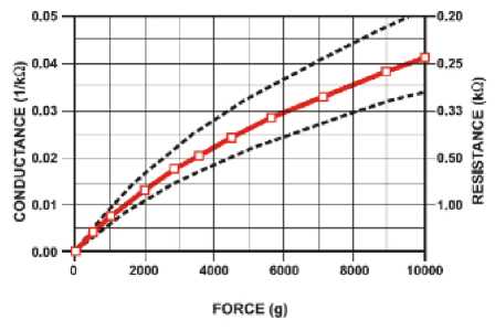
Fig.6. Conductance Vs Force(0-10Kg)
G = Conductance
F = Force
A = Maximum conductance
B = The force with which the maximum conductance is half the maximum conductance.
Equation (1):-
G =
aF
(b + F)
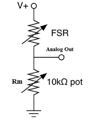
Fig.7. Voltage Divider
In asynchronous mode, only data is required, the data does not need to be transmitted at a constant speed and data is typically sent as a block. It allows more DTR (data transfer rate) if you keep all other factors constant.
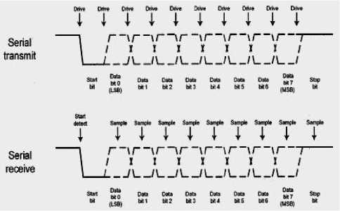
Fig.8. waveform design of data transmitter and receiver.
The voltage divider between output voltage and input voltage can be expressed by the Equation(2):-
RmVi
Vo=-----
Rm + R
Vi is the input voltage, Vo is the output voltage, Rm is the resistor connected in series with the FSR, and R = 1 / G.
Input voltage is Vi, Output voltage is Vo, Series-connected resistance with the FSR is Rm, and R = 1 / G.
From Equation(2)
aRmViF Vo = —-----—-
F(aRm + 1) + b
If,
b
F « t-=--- tt (aRm + 1)
It is linear.
Table.1.
|
Force (lb) |
Force (N) |
FSR Resistance |
(FSR*R) fl |
Current thru FSR+R |
Voltage across R |
|
None |
None |
Infinite |
Infinite! |
0 mA |
OV |
|
0.04 lb |
0.2 N |
30КП |
40 KO |
0.13 mA |
1.3 V |
|
0.22 lb |
1 N |
6 KG |
16 KD |
0.31 mA |
3.1 V |
|
2.2 lb |
10 N |
1KQ |
11 K0 |
0.45 mA |
4.5 V |
|
22 lb |
100 N |
250 0 |
10.25 K0 |
0.49 mA |
4.9 V |
-
V. USART Communication
In synchronous mode, data and clock are necessary; data is transmitted at a constant rate and data is typically transmitted, one byte at a time.
-
VI. Embedded C
During the years of microprocessor-based systems, we are developing programs for using counters and taking EPROM. There was no mechanism to find the program executed. They demonstrated the effectiveness of the program, such as LEDs and switches. They are very expensive and not very consistent but have fewer developers, a circuit emulator (ICE). At the same time, the use of a set of the processing system of language program was to reduce integrated movement with arbitrary compact embedded C language. C programming language is the most widely used processor/controller integrated. Arrays are also used, in particular, however, to implement parts of the code, such as efficiency of synchronization code extension, but they are very important.
Note:
-
1. Assembly language comparison was written in C code, more affordable and scalable, more consistent for all platforms.
-
2. The C compiler is currently in practical use for C integrated campaign and now many experienced programmers
-
VII. USBASB Programmer
USBasp is an integrated USB controller based on Atmel AVR control circuit. It consists of single or ATmega8 ATmega88 and passive part pair. The programmer is using the only USB firmware driver. No special USB driver is required. You need to install to Windows USBASP driver, use this programmer. There is a possibility that the USB power supply is actually too small and the possibility that the large capacity USB drive will be damaged may be too small. With the general 100 mA, more cards need to be equipped with separate sources. By operating the bridge figure 8, developers can set different power options. The program needs to allow the programmer to support and talk for software and chip purposes. To do this, you can perform software support reading (read or AVR flash backup). If the operation succeeds, it means that it can communicate with the software supported by the programmer and connect to the target board. If that fails you need to find the cause. The controller will operate more stable if the bridge "slow clock" (<1.5 megahertz) is shorted. Oscilloscope programming 062 (06201 P, 06201 KP or 06202 KP) is used. Pin head is compatible with time oscilloscope link.
However, in order to load the program (HEX file) of the microcontroller equipped with the USBASP programmer, appropriate software is necessary. Fortunately, an open free program for downloading, downloading and manipulating is combined with flash, EEPROM and microcontroller AVR programmer code. This is part of the software package. You can easily install Sinaprog or extreme burner, which has a number of Atmel AVR open source software development tools.
-
VIII. 7805 Voltage Regultor Ic
78XX (sometimes L78xx, LM78xx, MC78xx ...) is a family of linear integrated circuit autonomous fixed voltage regulators. The 78XX family is used for electronic circuits that require a regulated power supply for general use and low cost ease. The family the IC family 78XX (with 12 volt 7812, e.g. 7805 has 5 volt output), 2 digit output voltage is exchanged. It is a 78XX
line positive voltage regulator: it generates a positive voltage relative to the common base. Supplemental negative voltage regulator is 79xx related equipment line. It can be used in combination to provide positive and negative voltage to the same power supply circuit as 78XX. The 78XX integrated circuit has a general setting, 7808 (8 V) 7809 (9 V) 7810 (10 V) 7812 (12 V) 7815 (15 V) 7818 (18 V) and 7824 7805 (5 V), 7806 (6 V) (24 V). 7805 is the most common because its stable 5 volt power supply provides the most power for the TTL component most. It is less common in the so powerful version like the LM78 LMxx series (500 mA) and the LM78L xx (100 mA) from the National Semiconductor series. Some devices provide slightly different voltages, as usual, as are the LM78L62 (6.2 volts), LM78L82 (8.2 volts) and ST Microelectronics L78L33ACZ (3.3 volts).
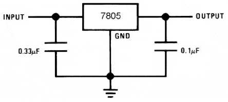
Fig.9. Schematic of Voltage Divider.
-
IX. System Setup
In this research work we need configure and setup a system by this following below five steps:
-
(A) Configure and Pair of two Bluetooth module
We need to configure both modules. To do this, we need to switch to AT command mode, where we are how to do that. First, you need to connect the wiring diagram of the RS232 TTL, Bluetooth module. We need to connect the RS232 TTL pins to the HC-05 Bluetooth module pins as shown in fig.11.
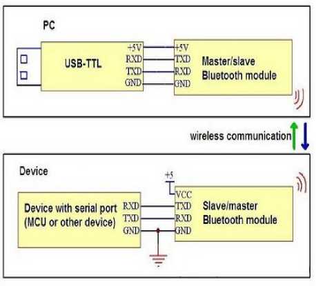
Fig.10. Configuration of the Bluetooth modules.
Therefore, the RX pin of RS232 must be connected to the Bluetooth module TXD pin, and vice-versa. Now the Bluetooth module enters the command mode you need to take a small button on the terminal to provide the module. The Bluetooth module flashes, LEDs every 2 seconds, which means that we entered correctly in AT command mode. Make sure that connection of RX and TX lines should be proper. So we need to run a PUTTY tool to serial monitor and choose "both NL and CR" and the "38400 baud" rate is not the default baud rate of the Bluetooth module. Then it is ready to send commands and their formats. All commands start with "AT" ending with "?" When followed by "parameter name" followed by "+". When we enter the new value of this parameter, we return the value of the current parameter or, the "=" sign.
-
(B) Configuring Slave Bluetooth module
Confirm the need to return the message to "OK" when you enter "AT" command. So, when we get in, "AT+UART?" We need to get back to the sequence showing the default baud rate 38400, "ROLE=0" Which means that the Bluetooth device which is messaging is in the slave mode. "AT+ADDR?" which means that the Bluetooth device is finding the address: XXXX: XX: XX: XX.
This address is requiring the master configuration. In fact, when in the slave configuration of the address is everything we need, and we will change many of the various parameters such as name, transmission speed, password etc.,
-
(C) Configuring Master Bluetooth module
Set up another Bluetooth module as the master device. First, and to ensure that it is the same as the input slave device 38400, check the baud rate and "AT+ROLE=1" set the Bluetooth module as the master device. After using "AT+CMODE=0", establish the command "AT+ BIND=XXXX, XX, XX, XX" connection "constant direction mode" command to set the address of the previously marked slave device.
When we write the address we need to use a comma instead of two points. Also, we woke up a master to connect to any device within its transmission range and the step before the command '0' introduced '1' instead of 'AT+CMODE' skipped although it may be.
However, this is necessary for the basic configuration of the Bluetooth module to re-activate modules within seconds that the master connects to the slave, currently acting as the master and slave devices, connecting the normal data It's all. Both modules are flashing every 2 seconds, indicating a successful connection .
-
(D) Installing the designed circuit board in the helmet
The circuitry installed in a helmet is Transmitter circuit designed by an atmega8 microcontroller with the internal supply of 5V given by a 7805IC through battery. In this device we used Force Resistive Sensor (FSR) which is used to receive the analog output according to the applied force. These analog data will read by using analog to
digital converter (ADC) pin of microcontroller. The value will read according to the reference voltage (Vreff). Master Bluetooth module is as a transmitter which transmits the data received from the microcontroller. Bluetooth module is communicated with USART pins of the microcontroller. Logic given in the program is that, the analog voltage is greater the reference voltage then usart transmits the data from master to slave. Finally, the whole module is implemented in the helmet as shown in figure.12.
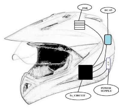
Fig.11. Circuit board in the helmet.
-
(E) Installing the designed circuit board in the vehicle
According to this research device the circuitry should installed in a vehicle is Receiver circuit designed by an atmega16 microcontroller with the internal supply of 5VDC given by an adaptor from the vehicle battery. In this device we used Bluetooth module to receive the data, it is in the mode of slave. The 16*2 LCD is interfaced to one of the port of the microcontroller to display the current statues. Microcontroller initializes a pin as output to the relay with the help of transistor.
-
X. Connected Modules With Working Principles
(A) Working of Receiving Device
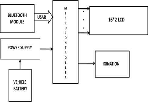
Fig.12. Connectivity of Receiver Block Diagram
In this research work the data which is transmitted by the master module is received by slave module which is present in vehicle. The slave Bluetooth module forwards the data to the microcontroller. For receiving the data the controller should enable the receiver mode. As per the data received is “HIGH” and “LOW” therefore if it receives high then the display monitors the statues “HELMET CONNECTED” and the relay works as a closed switch by this switching the ignition turns “ON”. At this condition the vehicle is ready to start and can move on. Or else if it receives low then the display monitors the statues “HELMET DISCONNECTED” and the relay works as an open switch by this switching the ignition turns “OFF”. At this condition the vehicle is not ready to start. To operate the relay we used transistor as a switch condition. This condition is applicable when to operate high voltage device with low control signal. The supply is given from the vehicle battery by using voltage adapter of output 5V dc with 2Amp. Here, the 16*2 LCD is connected in 4-bit mode.
(B) Working of Transmitted Device
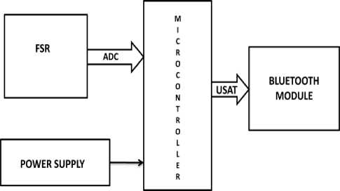
Fig.13. Connectivity of Transmitter Block Diagram
In this research work we considered that the output of the Force Sensing Resistor (FSR) gives the output signal according to the force is applied on it. The result of this FSR is shown in the above tabular Table.1 and graphical form Fig.4. The FSR output is in analog form which is necessary to convert into digital form. Due to this reason we enabled ADC in the microcontroller at PORTA.
The master module acts as a transmitter in this device. To transmit the data we need to enable the Transmit mode from the USART of the microcontroller. The condition to communicate the master module and the microcontroller is to cross connect the pins such as Tx pin of Microcontroller to the Rx pin of Master Bluetooth module. Finally, we applies a logic in the controller i.e. if the FSR output is greater than the reference voltage (Vreff) then it transmits “HIGH” or else if the reference voltage is less then it transmits “LOW”. The total circuitry works on 5V dc supply it has been provided by a battery source.
-
XI. Flowchart And Representation
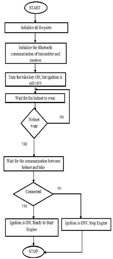
Fig.14. Flowchart and representation of the innovation.
By this research we are implementing this device for the safety of the driver. In this research work we firstly, Initialization of all the ports and Bluetooth modules are ready to communicate. The driver should key on the ignition. Now, the driver has to wear the helmet to step on next otherwise it waits until the helmet to wear. Then the helmet and the bike have to communicate, if helmet is connected the ignition turns “ON”. Now the engine is ready to start. Else, if helmet is disconnected the ignition turns “OFF”. Now the engine is not in a state to start. Now, we can have a safe journey.
-
XII. Innovated Hardware
The proposed Research work is implemented in real time. The actual interface is shown in following Fig.15 and Fig.16. In the form of screenshot interfaced with proposed necessity of helmet idea. The proposed work is found accurate and kept under testing of 9 days up to 495 kilometers.
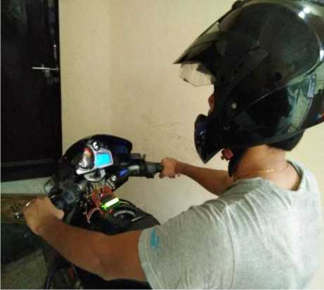
Fig.15. Innovated picture of helmet is connected.
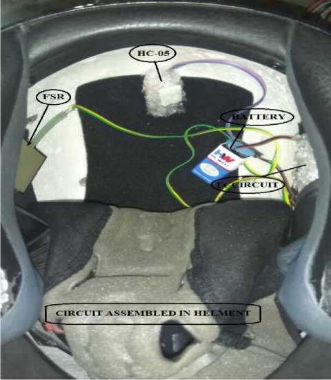
Fig.16. Circuitry setup in the helmet.
-
XIII. Future Scope
-
1. This proposed project can be implemented in BS-IV vehicles.
-
2. Further we can make helmet is compulsory (without helmet we can’t ride the bike).
-
3. Protect the driver life in accidents.
-
4. Decrease the death rate in road accidents.
-
XIV. Conclusion
The proposed Smart Helmet is tested and implemented in helmet and vehicle successfully. This work can also implement in the other application domains. The project has showed that the bike ignition will start if the helmet is worn. So, it will automatically decrease the effect from accident and it can avoid bike from being stolen. Executing the wireless system which Bluetooth Module to send signal from helmet device to the bike device. This wireless connection is better than wired link.
Acknowledgement
The authors of this paper would resemble to expressive great appreciation to ITM University Gwalior.
References Advanced control of switching ignition by smart helmet
- Smart Helmet with Sensors for Accident Prevention Mohd Khairul Afiq Mohd Rasli, Nina Korlina Madzhi, Juliana Johari Faculty of Electrical Engineering University Tecnology MARA40450 Shah Alam Selangor, MALAYSIAjulia893@salam.uitm.edu.my
- A Smart Safety Helmet using IMU and EEG sensors for worker fatigue detection Ping Li, Ramy Meziane, Martin J.-D. Otis, Hassan Ezzaidi, REPARTI Center, University of Quebec at Chicoutimi Chicoutimi, Canada Email: Martin_Otis@uqac.ca Philippe Cardou REPARTI Center, Laval University Quebec, Canada Email: pcardou@gmc.ulaval.ca)
- Harish Chandra Mohanta, Rajat Kumar Mahapatra and Jyotirmayee Muduli(2014)”, Anti-Theft Mechanism System with Accidental Avoidance and Cabin Safety System for Automobiles”, International Refereed Journal of Engineering and Science (IRJES), Vol. 3, No. 4, pp. 56-62.
- Laxmi R, Saritha B, Priyadharshini B,Deepeka S and Vijay J (2011), “Drunken Drive Protection System”, International Journal of Scientific & Engineering Research, Vol. 2, No. 12, ISSN: 2229-5518.
- Boutigny, Pierre-Henri; Nguyen, Huy Anh; Raoulx, Denis; , "1GHz Analog Comparator and Switch Matrix for 8-Channel Analog Data Acquisition System," Solid-State Circuits Conference, 1988. ESSCIRC '88. Fourteenth European , vol., no., pp.106-109, 21-23 Sept. 1988
- Hart, B.L.; , "Precision voltage-divider circuit," Electronics Letters ,vol.7, no.23, pp.679-680, November 18 1971
- Jianyun Ni; Jing Luo; "Microcontroller-based engineering education innovation," Educational and Information Technology (ICEIT), 2010 International Conference on , vol.3, no., pp.V3-109-V3-112, 17-19 Sept. 2010
- Ian, Paul. "Wi-Fi Direct vs. Bluetooth 4.0: A Battle for Supremacy". PC World. Retrieved 27 December 2013.
- F.L. Lewis. "Wireless Sensor Networks." Smart Environments: Technologies, Protocols, and Applications, ed. D.J. Cook and S.K. Das, John Wiley, New York, 2004. Automation and robotics research institute. 26 Oct. 2013
- Yvonne Toft; Geoff Dell; Karen K Klockner; Allison Hutton (April 2012). "Models of Causation: Safety". In HaSPA (Health and Safety Professionals Alliance). OHS Body of Knowledge(PDF). Safety Institute of Australia Ltd. ISBN 978-0-9808743-1-0.Wigmore, I. (June 2014). "Internet of Things (IoT)". TechTarget.
- Seelam Vasavi Sai Viswanada Prabhu Deva Kumar, Shyam Akashe “Implementation of GSM Based Security System with IOT Applications” I. J. Computer Network and Information Security, 2017, 6, 13-20.
- Sultan A. Alhumrani and Rizwan J. Qureshi “Novel Approach to Solve Resource Constrained Project Scheduling Problem (RCPSP)” I.J. Modern Education and Computer Science, 2016, 9, 60-68.
- Yadwinder Singh, Lakhwinder Kaur “Obstacle Detection Techniques in Outdoor Environment: Process, Study and Analysis” I.J. Image, Graphics and Signal Processing, 2017, 5, 35-53.
- Ashraf Adamu Ahmad, Aminu Inuwa Kuta, Abdulmumini Zubairu Loko “Analysis of Abdominal ECG Signal for Fetal Heart Rate Estimation Using Adaptive Filtering Technique” I.J. Image, Graphics and Signal Processing, 2017, 2, 19-26.
- Olutayo V.A, Eludire A.A “Traffic Accident Analysis Using Decision Trees and Neural Networks” I.J. Information Technology and Computer Science, 2014, 02, 22-28.
