Alternative method of solar simulation for thermal vacuum tests of spacecraft

Author: Shevchuk A.A.
Journal: Siberian Aerospace Journal @vestnik-sibsau-en
Section: Aviation and spacecraft engineering
Article in issue: 4 vol.22, 2021.
Free access
Solar simulators based on gas-discharge xenon lamps, used to obtain the thermal state of objects for thermal vacuum testing of spacecraft, are one of the key, most complex and energy-consuming elements of test equipment. Complexity of the optical system, the large number of optical elements, the need for constant monitoring of their condition, tuning and adjustment by highly qualified personnel significantly complicate obtaining of required luminous characteristics, mainly spatial uniformity of irradiance. Another common drawback is their low energy efficiency, which does not exceed 10 %. We proposed an alternative method of solar simulation using solid-state luminous sources – high-efficiency LEDs, with their placement without a bulky and complex optical system directly in a thermal vacuum chamber. At the same time, one of the most difficult problems of adapting to the conditions of thermal vacuum tests is to provide the necessary luminous characteristics. The required wavelength range, spectral match is obtained by combining assemblies of high-efficiency LEDs of six different wavelengths and halogen lamps. We carried out a number of experiments, including measuring the luminous characteristics of alternative luminous sources and mathematical modeling of the matrix emitter. As a result, the possibility of using the proposed method for thermal vacuum tests of spacecraft was confirmed; the luminous characteristics of the model meet the requirements, and in terms of uniformity of irradiance and energy efficiency, they significantly exceed those of traditional solar simulators.
Thermal vacuum tests of spacecraft, solar simulator, light emitting diode, halogen lamp
Short address: https://sciup.org/148329598
IDR: 148329598 | UDC: 621.32; 629.78 | DOI: 10.31772/2712-8970-2021-22-4-672-686
Text of the scientific article Alternative method of solar simulation for thermal vacuum tests of spacecraft
Solar radiation simulators (SRSs) create a stream of pulsed or continuous radiation, the characteristics of which are close to the characteristics of solar radiation both in atmospheric (AM0, Air Mass 0) and ground (AM1, AM1.5, etc.) conditions. The most complex, energy-consuming and expensive of them are constant-radiation SRSs used in thermal vacuum tests (TVT) of spacecraft (SC). In the course of TVT, vacuum and temperature conditions are simulated that are close to those of near-Earth outer space, and SRS, as one of the key elements of test equipment, is used to obtain the thermal state of objects of thermal vacuum tests – SC as a whole or their constituent parts [1; 2].
The emission spectrum of the Sun in open space conditions is close to the emission spectrum of a blackbody with a temperature of 5960 K (fig. 1). The thermal effect of the Sun in the entire wavelength range, or energy irradiance (EI), is defined as the amount of solar radiation per unit area:
E = | I (к) d к , (1)
where E – solar radiation, W/m2; λ – wavelength, нм; I ( λ ) – intensity of solar radiation per unit wavelength, W/m2∙nm.
The average value of the solar EI under atmospheric conditions, or the solar constant, is 1366 W/m2.
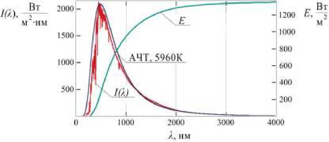
Рис. 1. Спектральное распределение солнечного излучения условий AM0
Fig. 1. AM0 spectral distribution
In terms of lighting characteristics, currently operating large-sized domestic solar simulator for thermal vacuum tests SC are imposed the following basic requirements:
– irradiance level – 1340–1440 W/m2;
-
– uneven distribution of irradiance in the working plane up to 15 %;
-
– spectral distribution close to the extraatmospheric spectrum of the Sun in the wavelength range 200–2500 nm;
-
– non-parallelism of the luminous flux is not more than 4° [2].
Gas-discharge xenon lamps [3] are traditionally used as light sources of solar simulator for thermal vacuum tests of SC, which, due to their peculiarities, cannot be placed directly in a thermal vacuum chamber. Therefore, to obtain the working field on the test object, a bulky and complex optical system is used from a large number of reflective and refractive elements. The light fluxes of gas-discharge xenon lamps are focused in optical mixers with the help of primary optics, then they are directed through the optical input units into the interior of a thermal vacuum chamber, where they are defocused again with the help of one or several collimating mirrors of complex shape, forming a uniform working field on the test object. At the same time, the level of achieved spatial uniformity of the irradiance directly depends on the accuracy of tuning and alignment of all elements of the optical system and the constant monitoring of their condition.
An example of a large-sized solar simulator of a traditional design is shown in fig. 2.
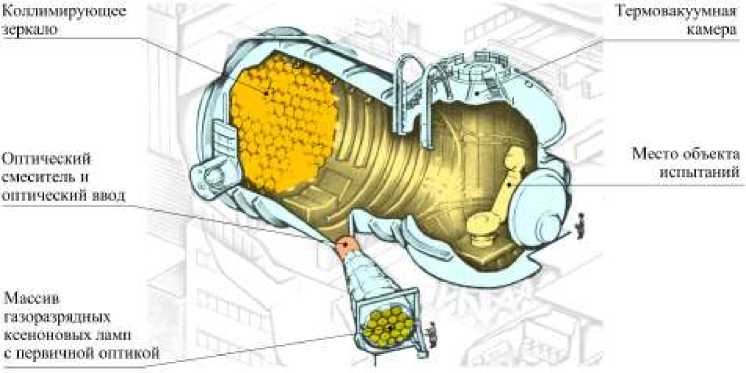
Рис. 2. Крупногабаритный ИСИ Европейского космического агентства
Fig. 2. SRS large-size solar simulator
Statement of problem
Among the general disadvantages of traditional solar simulator, the most significant are:
-
– the difficulty of obtaining high accuracy of simulation, first of all, the spatial uniformity of irradiance;
-
– low energy efficiency due to the low efficiency of gas-discharge xenon lamps, the remoteness of light sources from the test object, and high losses in a complex optical system. Even with the most careful manufacturing and fine adjustment of all optical elements, the energy efficiency of traditional SRS does not exceed 10 % [2; 4];
-
– small, about 500 hours, resource and high cost of light sources;
-
– complexity and high cost of operation with the participation of highly qualified personnel;
-
– long preparation time for testing.
It should be noted that traditional solar simulator has practically reached their perfection for several decades. Further improvement of their light characteristics is possible only to a small extent and at the cost of a significant increase in cost and complexity of design.
Despite the fact that the light characteristics of the existing large-sized domestic solar simulator meet the requirements of the vast majority of thermal vacuum tests cases, in the very near future they may turn out to be insufficient. For example, with ongoing tightening of requirements for automatic communication, navigation and geodesy satellites, transition to new frequency ranges, the requirements for accuracy characteristics of dimensionally stable precision spacecraft structures, such as large antennas, antenna panels, and truss structures, also increase. At the same time, at the stage of ground experimental testing, when confirming the stability of their geometric characteristics under thermal vacuum tests conditions, a higher accuracy of simulating solar radiation will be required, mainly in terms of stability and uniformity of the temperature field.
Consequently, new, alternative methods and solutions are needed to radically increase the accuracy of simulation and reduce the cost of thermal vacuum tests using solar simulator.
Solutions
Until recent years, gas-discharge xenon lamps, due to their good spectral match and high power, were considered, although the most expensive, but practically no alternative light source. However, the emergence and rapid development of new solid-state light sources, high-performance LEDs, made it possible to create simple and efficient solar simulator on their basis [5; 6]. When used in solar simulator for TVT of spacecraft, solid-state sources can be placed directly in a thermal vacuum chamber without a bulky and complex optical system, in the immediate vicinity of a test object. The most rational design of the emitter of such a solar simulator is in the form of a two-dimensional array (matrix) with distributed parameters [7; 8], consisting of many point sources - high-performance LEDs with simple primary optical elements (fig. 3). If the distance to a test object is several times greater than the distance between neighboring point sources of the matrix, their light fluxes, mixing many times, form a fairly homogeneous working field. At the same time, it is also rational to compose the emitter from a large number of light modules of small size. This will allow using only minimum required number of modules in accordance with the actual configuration of the test object and further improve the energy efficiency of the SRS.
A preliminary analysis shows the advantage of solar simulator based on LEDs in terms of the vast majority of light, operational, technical and economic characteristics [8]. Moreover, there are already based on LEDs solar imitators mass-produced by foreign manufacturers [9; 10]. However, all of them are designed for testing solar photovoltaic cells under AM1 or AM1.5 ground conditions, in a narrow spectral range of 400–1100 nm and with an EC level of up to 1000 W/m2. To adapt the LED solar simulator to thermal vacuum tests conditions, it is necessary to solve a number of problems that completely change its design. First of all, you need to ensure:
-
1. Light characteristics:
-
– irradiance level corresponding to the solar constant, not less than 1366 W/m2;
-
– spectral range, extended in the infrared region, up to 2000 nm;
-
– significant, several meters, distance to the test object and the size of the working field;
-
– high directivity of a light flux without a component of scattered radiation.
-
2. Thermal mode:
– thermal insulation of a solar simulator emitter with the removal of excess heat release outside the thermal vacuum chamber;
– thermal stabilization of LED crystals at any temperature conditions of thermal vacuum tests.
-
3. Choice of materials with minimal outgassing that do not affect the vacuum mode of thermal vacuum tests.
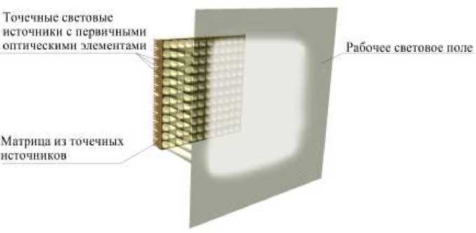
Рис. 3. Излучатель ИСИ в виде матрицы из точечных источников
Fig. 3. Emitter of solar simulator in the form of a matrix of point sources
The most difficult of these tasks is to provide the necessary light characteristics. Since the maximum radiation intensity of monochrome LEDs is concentrated in a narrow range, radiation from several groups of LEDs of different wavelengths is combined to obtain a continuous spectrum. However, in order to obtain high directivity of the light flux required for the case of TVT, each LED must have a primary optical element, which will not allow placing a sufficient number of groups within the matrix. On the other hand, the main obstacle to obtaining advanced up to 2000 nm of the SRS spectrum is high cost, narrow emission band and low efficiency of existing infrared LEDs.
To solve the problem, a simple and effective method has been proposed for combining LEDs of various wavelengths in the visible region and halogen incandescent lamps in predominantly infrared region of the solar spectrum. Moreover, if the spectra of these two types of light sources have a region of joint emission, the number of LEDs of different wavelengths required to obtain a continuous spectrum of light-emitting diodes can be reduced by several times. This makes it possible to use integrated LED assemblies of several different LEDs with minimal radiating surface dimensions together with one common optical element [11].
Thus, it is most rational to make an SRS emitter based on a combination of high-performance LED assemblies in the predominantly visible region and halogen lamps in the predominantly infrared region, placed in a matrix with uniform alternation. An example of placing a combined emitter in a horizontal thermal vacuum chamber is shown in fig. 4.
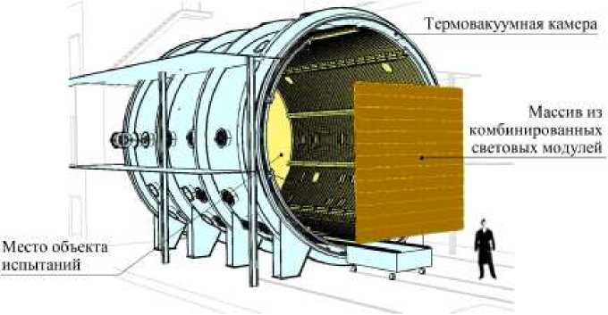
Рис. 4. Размещение комбинированного излучателя ИСИ в термовакуумной камере
Fig. 4. Placement of a combined luminous emitter in a thermal vacuum chamber
Experimental procedure
To check the compliance of combined matrix emitter of the solar simulator with the requirements, modeling of its light characteristics was carried out.
As light sources in the predominantly visible region, highly efficient LED assemblies LED ENGIN LZ7 manufactured by OSRAM [12] were selected from LEDs of six wavelengths and emitting surface dimensions of 7x7 mm (Table 1). The maximum electrical power consumed by the LED assembly reaches 50 watts.
Table 1
The main parameters of the integrated LED assembly LED ENGIN LZ7
|
Parameter |
LED Assembly Crystals |
|||||
|
Wavelength, nm |
449 |
495 |
519 |
522 |
600 |
622 |
|
Quantity in assembly |
1 |
1 |
1 |
2 |
1 |
1 |
|
Forward voltage, V |
3.2 |
3.8 |
3.5 |
3.2 |
3.6 |
2.4 |
|
Maximum forward current, A |
3 |
1 |
3 |
2.5 |
1.5 |
2.5 |
|
Maximum temperature in operation mode, °C |
125 |
|||||
|
Temperature in idle state, °С |
–40 … +150 |
|||||
The total radiation of the selected LED assembly is limited to the red region of the spectrum, which implies the use of halogen incandescent lamps with a maximum radiation of about 750 nm in the predominantly infrared region. The emission spectrum of halogen lamps is close to the radiation of a black body (fig. 5), the wavelength corresponding to the maximum radiation and the temperature of the black body, or the color temperature of the lamp, are interconnected by the formula:
Xmax = Ь ' 10 9 , (2)
max where λmax – wavelength corresponding to the emission maximum, nm; T - color temperature, K; b – constant Vina equal to 2,89777 ∙ 10–3 K∙m.
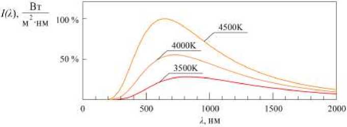
Рис. 5. Спектральные распределения галогенных ламп различных цветовых температур
Fig. 5. Spectral distributions of halogen lamps of different color temperatures
At the same time, lamps with an axial filament are preferred, which makes it possible to use simple and effective primary optical elements with them – parabolic reflectors.
The most affordable and fully meet the listed requirements are automotive H1 high beam halogen lamps with a wide range of color temperatures (fig. 6).
Fukurou HI 4301FI 3300
Koito III Whitebeam v3 ^^^^^^^^^^^^^^Bl 3700
Philips HI VisionPlus+60 % ^^^^^Щ3200
Philips Hl X-tremeVision *130% 3400
OSRAM 111 Cool Blue Intense i^^^^^^^^^MB 3700
OSRAM HI Night Breaker Silver-100% ^^^^^^^МЗЗОО
OSRAM III Night Breaker Laser+150 % i^^^^^^^^^^B 3500
SVS HI White ver. 2.0 ^^^^^^MBiM480t)
SVS H I Intense -130 % ver. 2.0 ^^^^^^^^Bi3400
General Electric HI Megalight Ultra +130 % fi^^^^^^^^^^^S! 3400
OSRAM HI Original i^^^^^^^^M 3200
Philips H1 Vision 130 % L ^^ 13200
Fukurou HI 4301F1 ^^^^^^^B 3100
Тип галогенной лампы Цветовая температура, К
Рис. 6. Цветовые температуры галогенных ламп H1 различных производителей
Fig. 6. Color temperatures of H1 halogen lamps from different manufacturers
H1 halogen lamps manufactured by OSRAM with a color temperature of 3700 K and a maximum power consumption of 55 W were chosen as a light source in the predominantly infrared region.
Primary optics for light sources was selected from commercially available compact optical elements with round light distribution and the smallest distribution angle of 6°. TIR optical elements based on the principle of total internal reflection (eng. Total Internal Reflection) [13; 14], for halogen lamps – parabolic reflectors.
The initial values of light power and spectral distributions of light sources were measured under normal conditions. To measure spectral distributions, a spectrum measurement system based on two MDR-206 monochromators and a PC with specialized software was used to determine the integral values of the irradiance. The monochromators are calibrated against reference light sources based on an incandescent lamp and a deuterium lamp. Additionally, to measure the levels of irradiation, a spectrally non-selective thermal radiometer FOA 020 with a small, almost point size of the measuring surface, calibrated by the method of direct measurements according to the State secondary standard of units of radiation strength and energy illumination of continuous optical radiation 2.1.ZZA.0010.2015, was used.
The spectral distribution obtained by combining LEDs of six wavelengths and a halogen lamp with separate regulation of their electric power is shown in fig. 7.
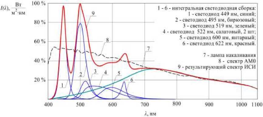
Рис. 7. Спектральное распределение комбинированного светового источника
Fig. 7. Spectral distribution of the combined luminous source
Compliance with the AM0 spectrum was determined according to the method given in GOST R IEC 609040-9 [15]. It should be noted that these requirements are redundant for the case of thermal vacuum tests, since [15] classifies the characteristics of the solar simulator for testing solar photocells that are extremely sensitive to the spectrum. However, even in this case, the spectral correspondence is within 0.75–1.25, which corresponds to the highest-class A (Table 2).
Spectral fit obtained by combining light sources
Table 2
|
Wavelength ranges, nm |
400–500 |
500–600 |
600–700 |
700–800 |
800–900 |
900–1100 |
|
Spectral match |
0.79 |
1.04 |
0.92 |
1.05 |
1.04 |
0.98 |
Further modeling of the characteristics of a single light module and an array of a large number of light modules was carried out in specialized software for optical design Zemax OpticStudio.
At the first stage, modeling of selected single light sources was carried out with primary optical elements. As initial data, the results of measurements of light characteristics, 3D models of light sources and their primary optical elements were used. The simulation results (fig. 8, 9) showed a good, with an accuracy of 5 %, agreement between the measurement results and the models obtained.
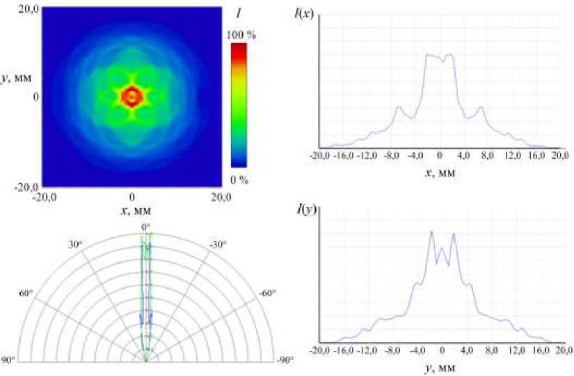
Рис. 8. Результаты моделирования светодиодной сборки с TIR оптическим элементом
Fig. 8. Simulation results for the LED assembly with TIR
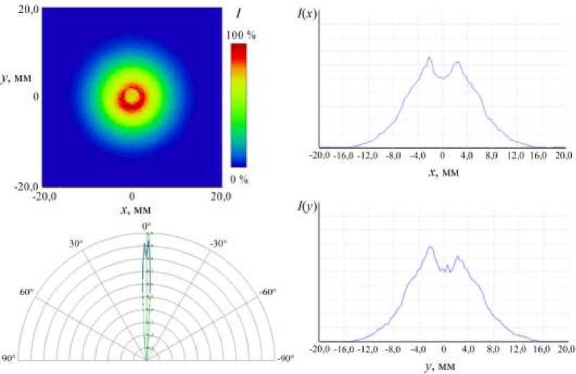
Рис. 9. Результаты моделирования галогенной лампы H1 с параболическим рефлектором
Fig. 9. Simulation results for the H1 halogen lamp with parabolic mirror
At the next stage, Zemax OpticStudio simulated the light characteristics of a single light module with dimensions of 310 × 310 mm, or 0.1 m2 (fig. 10), consisting of 18 LED assemblies and 18 halogen incandescent lamps with primary optical elements. The calculated electric power consumed by the module, according to the simulation results, did not exceed 720 W, while the power of the selected light sources was within half of the maximum.
Рис. 10. 3D-модель светового модуля на основе 18 светодиодных сборок и 18 галогенных ламп
Fig. 10. 3D model of a luminous module based on 18 LED assemblies and 18 halogen lamps
The resulting light characteristics of one module are used below as input data for modeling an array of 169 light modules in Zemax OpticStudio. Since, due to the dimensional limitations of most thermal vacuum chambers, distances to the test object are not more than 3 m of practical interest, distances from 0.5 to 3 m were modeled with a step of 0.5 m.
When determining the level and uneven distribution of irradiance, the working plane is divided into a grid of 20x20 sections (pixels). Average irradiance level in the working plane E , W/m2, calculated by the formula
E NX,' NyE,;-
E = j-j
Ny -Nv where Eij - integrated irradiance value in each of the 400 grid areas 20 (x)x20 (y), W/m2; Nx – number of measurements by x coordinate; Ny – the number of measurements along the y coordinate.
Deviation from the average level of irradiance for each measured area Q ij , %, calculated by the formula
Q j =
Eif - 100
100 — j--- E
The total value of the uneven distribution of irradiance in the working plane Q , %:
S Nx : Nyo..
Q ^ j = 1 Q j
.
Nv -Nv
The simulation results in terms of the level and uniformity of the irradiance distribution for each of the six distances are shown graphically in Fig. 11 and summarized in the general graph in Fig. 12. The results in terms of the parallelism of the light flux are shown in fig. 13 and in table 3.
Рис. 11. Моделирование массива из световых модулей на различных расстояниях от 0,5 до 3 м
Fig. 11. Modeling of luminous modules array at different distances
Рис. 12. Зависимость уровня и неравномерности распределения ЭО от расстояния до ОИ
Fig. 12. Dependence of the level and non-uniformity of the irradiance on the distance to the test object
Рис. 13. Зависимость концентрации энергии ИСИ от угла распределения
Fig. 13. Dependence of the energy concentration of solar simulator on the distribution angle
Table 3
Dependence of the solar simulator energy concentration on the distribution angle
|
solar simulator energy concentration P within the angle ϕ , % |
Angle ϕ , degree. |
|
|
4 |
6 |
|
|
Horizontal plane |
85 |
96 |
|
Vertical plane |
84 |
96 |
Results and discussion
The simulation results (fig. 11–13, tables 2–4) show that the obtained value of energy efficiency is at least twice as high as that of traditional solar simulator. The value of the spatial non-uniformity of the irradiance is at least three times lower than the maximum allowable value of 15 %. The model is optimized for a distance of 1.7 m to a test object, which is sufficient in most cases of thermal vacuum tests, at which the irradiance level is maintained at 1400 W/m2 and a low inhomogeneity equal to 3.5 %. The correspondence to the AM0 spectrum determined by the method [15] is within the highest-class A.
Table 4
Comparative light characteristics of the model and traditional solar simulator for TVT space craft
|
Parameter |
Pattern |
Traditional solar simulator |
|
Uneven distribution of EI in the working plane, % |
5.2–3.3 |
to 15 |
|
Energy efficiency, % |
19.5 |
5–10 |
|
Spectral compliance according to GOST R IEC 60904-9 |
class А |
|
It should be especially noted that the results obtained are far from limiting.
On fig. 11 it is clearly seen that the total irradiance level of the array of light modules reaches its maximum values in the center of the illuminated area, uniformly decreasing in the direction to the edges. Therefore, the spatial uniformity of the irradiance at the level of the entire array can be further increased by separately adjusting the power of the light modules. The spatial uniformity of the irradiance at the level of one light module can also be increased by using primary optical elements with light distributions that have not a round, but rectangular or hexagonal form.
It is also obvious that the use of primary optical elements with a smaller distribution angle will further increase the parallelism of the light flux, the uniformity of the irradiance distribution and the maximum distance to the test object.
Thus, the obtained light characteristics can be significantly improved by using primary optical elements manufactured taking into account the above requirements.
Conclusion
The emergence of the latest developments in light sources – high-efficiency LEDs – gives opportunities for implementing an alternative method of simulating solar radiation. The simulation results allow us to draw the following conclusions:
-
1. The possibility of creating a solar radiation simulator for thermal vacuum testing of spacecraft with the placement of light sources directly in the thermal vacuum chamber is theoretically confirmed.
-
2. The light characteristics of the model meet the requirements.
-
3. In terms of solar radiation simulation accuracy and energy efficiency, the obtained model characteristics significantly exceed those of conventional solar radiation simulators.
The next logical step is creation of a working model of an alternative solar radiation simulator and experimental confirmation of its characteristics in real conditions of thermal vacuum tests.
References Alternative method of solar simulation for thermal vacuum tests of spacecraft
- GOST R 56469–2015. Apparaty kosmicheskiye avtomaticheskiye. Termobalansnyye i termovakuumnyye ispytaniya. [State Standard R 56469-2015. Automatic spacecrafts. Thermal balance and thermal vacuum tests]. Moscow, Standartinform Publ., 2015. 11 p.
- Kravchenko S. V., Nesterov S. B., Roman’ko V. A., Testoyedov N. A., Khalimanovich V. I., Khristich V. V. [Approaches to creating integrated systems for optimization and testing of spacecraft]. Inzhenerniy zhurnal: nauka i innovatsii. 2013, No. 1 (13), P. 149–175 (In Russ.).
- Wang W., Laumert B. Simulate a ‘Sun’ for Solar Research: A Literature Review of Solar Simulator Technology. KTH Royal Institute of Technology website. 2014. Available at: http://urn.kb.se/resolve?urn=urn:nbn:se:kth:diva-154262 (accessed: 15.11.2021).
- Krat S. A. [Increase of solar radiation simulator efficiency]. Sibirskiy zhurnal nauki I tekhnologiy. 2011, No. 2 (35), P. 124–127 (In Russ.).
- Bazzi A. M., Klein Z., Sweeney M. et al. Solid-State Solar Simulator. IEEE Transactions on Industry Applications. 2012, No. 48, P. 1195–1202.
- Reynolds K. LED-based sun-simulator design: technical and commercial considerations. Photonics Spectra. March 2015, pp. 54-58.
- Plita F. Optical design of a fully LED-based solar simulator. PhD thesis. Loughborough, Loughborough University, July 2015. 186 p.
- Dvirniy G. V., Shevchuk A. A., Dvirniy V. V., Elfimova M. V., Krushenko G. G. [Analysis of LED-based solar simulator development capability for spacecraft ground testing applications]. Sibirskiy zhurnal nauki i tekhnologiy. 2018, Vol. 19, No. 2, P. 271–280 (In Russ).
- VeraSol-2 LED Class AAA Solar Simulator. Newport, Irvine, CA 92606, United States, 2021. Available at: https://www.newport.com/f/class-aaa-led-solar-simulators (accessed: 17.11.2021).
- Sun Simulator For Solar Panel Testing In LED Class A+A+A+. ECOPROGETTI, Padova, Italy, 2021. Available at: https://ecoprogetti.com/sun-simulator-for-solar-panel-testing-in-led-class-aaa (accessed: 17.11.2021).
- Dvirniy G. V., Shevchuk A. A., Pastushenko O. V. [Ways to improve the technical and operational characteristics of solar simulators for ground testing of spacecraft]. Reshetnevskiye chteniya: materialy XXIV Mezhdunarodnoy nauchno-prakticheskoy konferentsii [Materials XIV Int. scient. And pract. conf. “Reshetnev readings”]. Krasnoyarsk, 2020, Vol. 1, P. 268–270 (In Russ).
- OSRAM LED Engin LuxiGenTM LED Emitters. OSRAM, 2021. URL: https://www.osram.us/ledengin/products/luxigen/lz7.jsp (accessed: 04.06.2021).
- Talpur T., Herkommer A. TIR collimator designs based on point source and extended source methods. Proceedings of SPIE. 2015, Vol. 9629, P. 962906 962916.
- Moiseev M. A., Doskolovich L. L. Design of TIR optics generating the prescribed irradiance distribution in the circle region. Journal of the Optical Society of America A. 2012, Vol. 29(9), P. 1758–1763.
- GOST R MEK 60904–9–2016. Pribory fotoelektricheskie. Chast’ 9. Trebovaniya k harakteristikam imitatorov solnechnogo izlucheniya. [State Standard R IEC 60904–9–2016. Photovoltaic devices. Part 9. Solar simulator performance requirements]. Moscow, Standartinform Publ., 2017. 12 p.
