Aluminum busbar connection parts of the cell «flexible cathode descent – cathode bus»

Author: Kirko Vladimir I., Galemov Takhir T., Petrov Alexandr M.
Journal: Журнал Сибирского федерального университета. Серия: Техника и технологии @technologies-sfu
Article in issue: 5 т.6, 2013.
Free access
In the given article we present our results of research of aluminum joint parts of «cathodic flexible swith a cathode bus». Basing on the theoretical analysis and experimental researches, we present the method of molding of joint assembles in the casting mould, with an overheated fusion. The suggested method let us produce a high-quality junction without loss of electrolysers'series productivity and it also allows decreasing the operational expenditures.
Resistivity, pressure, contact, detachable joints, aluminum cell busbar
Short address: https://sciup.org/146114766
IDR: 146114766 | UDC: 537.312.9
Соединение алюминиевых деталей ошиновки электролизера «гибкий катодный спуск – катодная шина»
В металлургии, где используются мощные энергетические установки, остро стоит проблема уменьшения потерь при передаче электроэнергии от источника к потребляемому агрегату. Основные потери происходят на контактных соединениях, в частности при передаче электроэнергии от ошиновки алюминиевого электролизера к катодным спускам. В настоящей статье теоретически обосновывается и экспериментально подтверждается возможность соединения ошиновки алюминиевого электролизера к катодным спускам методом заливки бобышки перегретым расплавом алюминия.
Text of the scientific article Aluminum busbar connection parts of the cell «flexible cathode descent – cathode bus»
In metallurgy where multiwatt electric power installations are being used there is a nagging problem of decreasing energy losses at the electric power transmission from a source to the consuming installation [1, 2]. The main losses take place at electric contactsin particular at the power transmission from the aluminum cellbusbarto flexiblecathode strips (cathodic flexibles).
At present after the repair work one has to use 2 basic methods for connecting a cell to the series power circuit of the cell shell:
-
1. Electric-arc welding in argon of the preliminarily formed aluminum boss and cathodic flexible to the busbar (Fig. 1).
-
2. Forming a boss connecting the busbar and flexible by filling a mould preliminarily fastened to thebusbar surface with molten aluminum followed by heating the metal up to 1000 °С with the carbon electrode arc and agitation, whereupon the aluminum crystallizes and forms the contact joint between the flexible and busbar.
In strong magnetic fields the presence of a potential leads to a part of the technological electrolysis current flowing through the molten metal (the weldpool) connecting the busbars. The interaction of the
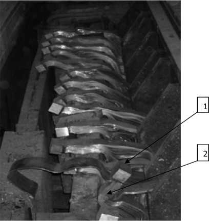
Fig. 1. Preliminarily formed aluminum bosses (1) on cathodic flexibles (2) before connecting to the cathode busbar with electric-arc welding in argon magnetic field with certainly directed transverse components of the external electric fieldforms a force throwing the liquid metal out of the welding zone.
The methods above don’t give an opportunity for quality welds on an operating cellbusbar without stopping the bath or decreasing its current loading that leads to the loss of productivity of the potlineand finally aluminum output decrease.
One of the most efficient methods to weld aluminum details in strong magnetic fields without electric-arc welding is that used by the firm Erico International Corporation of Solon, Ohio, USA, with the trademark ERICO [3]. The welding method is schematically represented in Fig. 2.
In the casting mould 1 there is loaded a mixture of an adding material and aluminum 3. There is used an exothermal reaction as follows: reducing agent + adding materials + metallic compound = heat + weld metal + slag + gases.
An aluminum powder is used as the reducing agent that can reduce a metal oxide (CuO) or its sulfate with the formation of Al2O3. In the process there is released 400 kcal/mol of heat. This reaction is highly exothermal. And when it is initiated the temperature of the adding metals is higher than their melting points. The adding materials form a melt directed into the meltingcavity (into the mould) after the aluminum plate 5 has beenmelted. The melt fills the meltingcavity between the busbars 2. And after crystallization it provides a good weld of the busbars being connected.
The method above can be effectively used when welding cathodicflexiblesbut has sufficient disadvantages. Firstly, details of graphite moulds are costly and short-lived. Secondly, a high price of adding and igniting materials and their high consumption limit the massive usage of the technology. Thirdly, when the exothermal reaction proceeds there is emitted a large amount of gases (Fig. 3). The latter prevents the method to be used in an indoor working area.
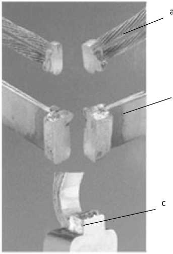
Some examples of the ropes (a), plates (b) and flexibles (c) welds by means of the aluminothermic welding by ERICO are presented in Fig. 4.
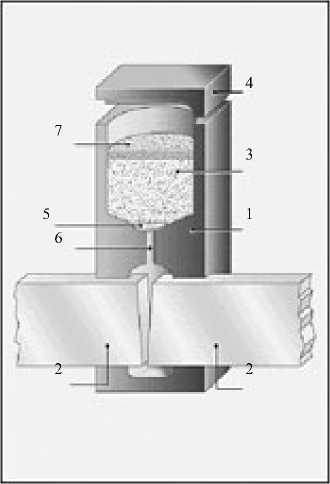
Fig. 2. Schematic diagram of aluminum busbars welding (ERICO): 1 – the castingmould; 2 – aluminum busbars; 3 – a mixture of an adding material and aluminum; 4 – a cover; 5 – an aluminum plate; 6 – a melting cavity; 7 – an igniting material (igniter)
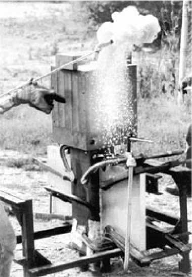
Fig. 3. Aluminum busbars welding with the method by ERICO
As has been noted above at present in smelters of the «RUSAL» company there are widely used two welding methods:
-
1. Electric-arc welding in an inert gas (argon).
-
2. Carbon-arc welding.
The photographs of the typical flexibles to busbar welds are presented in Fig. 5.
In both cases because of the arc instability in strong magnetic fields it isnecessaryeither to decrease the current loading in the potline or redistribute the busbar current during the welding process. The former and the latter have an adverse effect on the baths operation leading to their productivity decrease.
The common feature of all these welding methods is the overheated adding material compared to the aluminum with its melting point 658 °С.
In case of the aluminothermic welding the adding material temperature is about 1600 °С. When using the carbon-arc welding the cathodic flexible ends are fastened to the busbar and the mould is formed around them. The molten metal poured into the mould is heated up to 1000 °С with the carbon electrode arc and mixed for the oxide film removal from the surface of the details being connected followed by the molten aluminum crystallization that causes the contact joint between the flexibles and busbar to be formed.
Using the overheated metal witnesses the fact that a partial melting of the surfaces of the flexibles and busbar being connectedthrough the aluminum oxide layer Al2O3 is the necessary welding condition. A good weld of two surfaces is possible only in case of the Al 2 O 3 layer being destroyed.
в
Fig. 4. Examples of the ropes ( a ), plates (b) and flexibles(c) welds with the method by ERICO
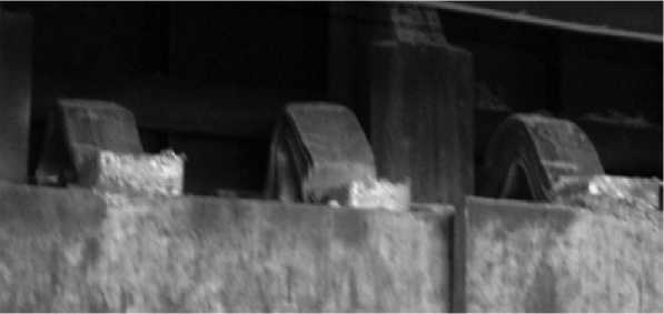
Fig. 5. Typical flexibles to busbarwelds
In paper [4] there has been shown that the equilibrium limiting wetting angle of the monocrystal Al2O3by the liquid aluminum steadily decreases with a temperature increase. Wetting (Q = 90°) begins taking place at a temperature higher than Т р =1050 °С. In Fig. 6 there is presented a temperature dependence of the angle for the Al2O3monocrystal wetted with the molten aluminum.
Thereupon, the best thermal contact with the oxide film surface preventing the possibility of an air interlayer formation will be provided at the melt temperature Тр > 1050 °С.
Moreover, as is generally known, aluminum oxide has several modifications the main ones of which are g-phase having the cubic syngony and density 3.63.77 g/cm3 and α-phase having the orthorhombic or hexagonal syngony and density 4 g/cm3. The phase transition of the g – to the α-phase begins at the temperature 1200 °С and ends at Т t a®g=1400 °С. Decreasing the phase transition temperature can occur to 800 °С in presence of fluorides such as AlF 3 . Decreasing the specific volume – 537 –
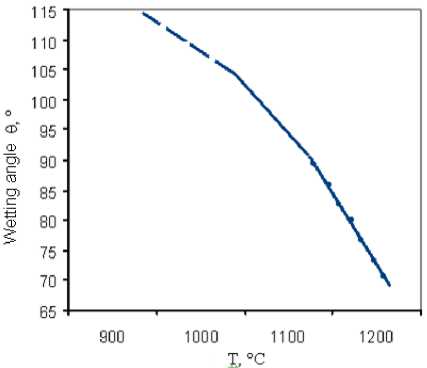
Fig. 6. Wetting angle vs. temperature for the Al2O3monocrystal wetted with the molten aluminum of a part of the oxide film also contributes to its brittle rupture due to the occurrence of negative internal stress.
Has been shown that the metal melting underneath the oxide film is the requirement for its destruction. The latter, as follows from thermodynamic calculations, is possible at the temperature of the poured melt Т ≥ 1100 °С.
Thus, there can be made a conclusion that the required melt temperature for the melting of the aluminum busbar’s and flexible’s surfaces depends on the thermalphysic conditions in the molten pool (in the mould).
When pouring the melt onto a boss some strongly turbulent flow conditions take place in the molten pool with the Reynolds number Re=106 and magnetic Reynolds number Re m > 10. Re m >> 1 in the molten pool is the evidence of astrong influence of the magnetic field induced by the current in the busbarand prevailing influence of the magnetic viscosity in the formation of the hydrodynamic flow. In this case the boundary layer thickness δ n between the melt and oxide film equals [3]:
δ п = 1 η р , (1)
п В σр where B – the magnetic field induction, ηр – the dynamic viscosity of the melt, σр–the conductivity of the melt.
For В = 10-3 T (100 G ); η р = 0,574∙10-3 Pa s and σ р = 0,3∙108 1/Ohm m
δ п = 4∙10-3м ≈ 4mm
L
For comparison, without the magnetic field the boundary layer thickness [5] δ п = ≅ 0,1 mm
Re
The tangential stress τon the wall washed with the turbulent melt flow will be:
dUp τ = ρрvhL , dy whereρp – the melt density, v′ – the stirring rate of the melt, L – characteristic mould dimension, dU p – velocity gradient in the turbulent flow, y – the distance from the wall. dy
For moulds v p ′ ≈ U р , and y ≈δ n .
In this case for U p = 3 m/s, δ n = 4∙10-3m, ρ р = 2370 kg/m3 and L = 0.1 m one obtains τ = 0.5∙106 N/m2 = 0.5∙102 N/cm2 (5 kg/cm2), that is, the tangential stress value is insufficient for the oxide film removal from the solid aluminum surface, but is sufficient enough for the loss of its stability and involvement into the hydrodynamic flow at the surfaces of the welded busbardetails having been melted.
In this case the film is involved into the turbulent flow of the melt, and at welding the busbar and flexiblesthere is no need for the fluxing agents being used.
The thermal flow qp onto the mould wall, when the turbulent melt flow influences it, equals [6]:
qp = StρpUpHp ,(3)
where St – the Stenton number, Н р = С р Т р – the melt enthalpy. The Stenton number depends on the melt flow conditions on the wall. In case of the laminar flow when the wall roughness ( а ) is lower than boundary layer thickness δ n :
StL = 1 (0,0032 + 0,221 Re-0'237).(4)
At turbulent flow
St t =------A--------.(5)
8(2lg L + 1,74) 2
a
As has been shown above the boundary layer thickness is determined by the magnetic viscosity of the melt and approximately equals 4mm, that is, the value is many times higher than the busbar surface roughness ifthe roughness is not made intentionally.
When the Reynolds number Re is 106, St L is 1.45∙10-3 and the melt temperature Т р equals 1200 °С, the heat convective flux onto a smooth busbar surface is q р = 7.6∙106 W/m2.
It is possible to increase the thermal flow value by means of the artificial formation of turbulent conditions. The latter implicates the intentional formation of the surface roughness having a size not less than the boundary layer thickness, that is, а ³ 4 mm.
For this purpose it is necessary to make crosscut grooves of more than 4 mm in width and depth on the busbar surface and place the flexibles in the mould in the form of steps with a lap (the step length h) of 4 mm, too.
In Fig. 7 there is presented a schematic diagram of the experimental connections of cathodic flexiblesto the cathode busbar by means of filling the details being connected in the mould with the overheated melt.
The aluminum was melted in the induction furnace and heated up to the temperature 1200 °С. The melt temperature was controlled with the pyrometer. Filling was made with the ladle 5 placed over the – 539 –
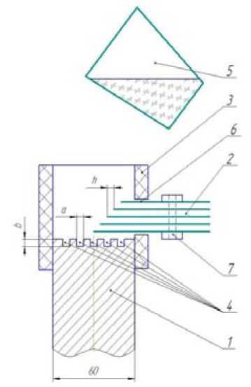
Fig. 7. A schematic diagram of the experimental connections of flexibles to the cathode busbar by means of filling with the overheated melt: 1 – the busbar, 2 – flexibles, 3 – the mould, 4 – milled grooves, 5 – a ladle with the liquid aluminum, 6 – a rectangular opening, 7 – a steel clip mould at 2530 cm in such a way that the melt should first wash the stepped part of the sheets 2 and then fill the ribbed surface of the busbar 1. The number of the aluminum sheets was 11.
To control the quality of the electric connection there were carried out some measurements of the electrical contact resistance by the 4-probe method. DC and AC sources were used in the measurements.
In Tables 1 and 2 there are presented the measurement results at DC and AC .
As can be seen from table 1, at AC the transient resistance R of 11 sheets to the cathode busbar connection is 5.53 ± 0.08 µOhm that equals 60.83 µOhm per sheet. When filling 60 sheets (the standard number of sheets for the cells C8BM) the transient resistance is 1.01 µOhm. From table 2 it follows that the transient resistance of 11 sheets at DC is 2.14 µOhm. And being recalculated for the 60 sheets it is 0.4 µOhm (the standard value of the transient resistance for the cell C8BM is 2.5 µOhm).
The work results have been patented [7].
Conclusions
It has been shown that the suggested technology of the cathodicflexible to the cathode busbar connection by means of filling the parts being connected in the mould with the overheated melt provides a quality connection without decreasing the potline current. The usage of the technology gives an opportunity to:
Table 1. Alternating current ( AC ) results
|
№ |
I (A) |
U (V) |
R (µOhm) |
|
1 |
240 |
132∙10-5 |
5,5 |
|
2 |
300 |
168∙10-5 |
5,6 |
|
3 |
480 |
265∙10-5 |
5,5 |
The average value R = 5.53 ± 0.08 µOhm
Table 2. Direct current ( DC ) results
|
№ |
I (A) |
U (V) |
R (µOhm) |
|
1 |
712 |
0,576 |
2,16 |
|
2 |
687 |
0,5506 |
2,15 |
|
3 |
678 |
0,5426 |
2,12 |
Theaveragevalue R = 2.14µOhm
-
1) increase the potline productivity (increasing the metal extraction by current);
-
2) decrease the electric energy loss in the flexible to busbar contact;
-
3) lower the operating costs associated with mounting and dismounting shunts;
-
4) eliminate the use of electric-arc welding.
