An Adaptive Method for Spiral Segmentation of Aztec Compact Code Images with Irregular Grid Structure

Author: Karnaushko V.A., Tishin I.I., Bezmaternykh P.V., Arlazarov V.L.
Journal: Компьютерная оптика @computer-optics
Section: International conference on machine vision
Article in issue: 6 т.49, 2025.
Free access
Reading Aztec codes is crucial in many practical applications and is well-studied for simple scenarios. However, mobile phone-based decoding is challenging under uncontrolled conditions and when the codes are printed on irregular surfaces like warped paper. The codes must remain readable, even though paper is flexible and not perfectly planar. Our novel method addresses this problem by considering local variations in adjacent symbol modules using conventional image processing techniques. It is particularly effective for Aztec Compact symbols lacking reference elements. We evaluate it on the specially modelled CoBRA-CYL-AZ dataset, including curved and cropped symbol examples, and further confirm the method's applicability on small dataset of the real photos. Both synthetic and real datasets are made publicly accessible on Zenodo. The proposed method achieves 0.59 accuracy on the CoBRA-CYL-AZ dataset, significantly outperforming the popular open-source readers: ZXing (0.02), ZXing-cpp (0.16), and Dynamsoft (0.16). While our method is applicable with any Aztec symbology, it features scanning distorted and damaged Aztec Compact codes.
Barcode reading, aztec code reading, image processing
Short address: https://sciup.org/140313278
IDR: 140313278 | DOI: 10.18287/COJ1790
Text of the scientific article An Adaptive Method for Spiral Segmentation of Aztec Compact Code Images with Irregular Grid Structure
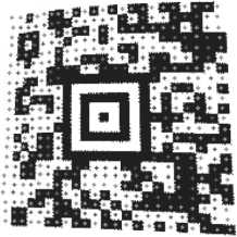
Aztec barcodes [1] are machine-readable visual symbols designed for compact data storage, eliminating manual data entry [2]. They are widely used in various industries and applications, notably: 1) ticketing systems for IATA airlines (boarding passing), and e-tickets for concerts, cinemas, and sporting events; 2) identity (or ID) documents: driver licences in the USA, Mexico, Latin America and other countries; 3) mobile payments and transactions: taxes in Russian Federation; 4) the Health Industry Bar Code includes Aztec Code for patient identification or drug labelling; medical data on wristbands is often encoded via these symbols. Some examples of Aztec Codes usage are presented in the Fig. 1.
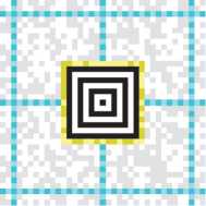
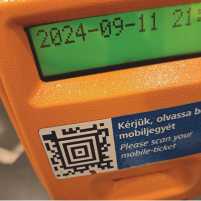

Fig. 1. (a) Aztec Code structure, where yellow color outlines the mode message layer, blue – the reference grid; (b, c) examples of real Aztec Codes
A flat image of the Aztec Code is obtained under favorable capturing conditions, but scanning curved or distorted Aztec barcodes is really important in real-world applications because these codes are often printed on non-flat surfaces or captured at awkward angles. In many cases Aztec Codes are printed on flexible surfaces like tickets, labels, or wristbands, which may not lie perfectly flat when scanned. Moreover, mobile scanning may be conducted under less-than-ideal conditions, including angled perspectives (e.g., boarding passes displayed on phones) or inconsistent illumination.
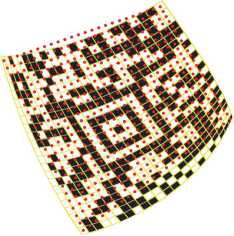
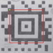
Real curved Aztec Codes present three main reading challenges. First, curvature distorts the square grid pattern, making decoding much more difficult (Fig. 2). Second, partial obstruction – where part of the code is hidden or bent – relies only on error correction usage [3]. Finally, light glare from reflective surfaces, such as laminated IDs, further complicates barcode scanning.
Like many other barcode types (or symbologies) Aztec Codes have built-in error correction codes. This redundancy may help in severely damaged code recovering. Furthermore, to simplify the problem of curved code reading, special patterns – namely timing patterns which are collected in a reference grid – are introduced into the code structure. These are lines of altering black and white modules which split the non-compact Aztec Code into separate small regions of modules as shown in Fig. 1a. The Aztec Compact Code, on the contrary, does not incorporate timing patterns in its structure, generally consists of fewer black and white modules, and has not 7, but 5 layers of the "aztec pyramid" in the center of the code. The latter observation allows to distinguish these two types of Aztec codes.
b)
Fig. 2. Example of Aztec Code modules localization: (a) fail in the projective model, (b) success in the desired model
Existing literature poorly addresses curved Aztec code reading. While non-compact and curved Aztec Codes were handled in paper [4], that approach can not be applied for compact codes due to the missing timing patterns. A new reading method is therefore needed. Furthermore, unlike QR Codes, publicly available datasets of Aztec codes, especially curved ones, are scarce, highlighting the need for a dedicated dataset.
Two main contributions of this work are the following: 1) the dataset CoBRA-CYL-AZ [5] comprising flat and curved Aztec Code samples; 2) a new method of curved Aztec Compact Code segmentation.
The article is organized as follows. In Section 1, we describe main aspects of Aztec code recognition and its existing scanning solutions. In Section 2, we propose our method of curved and cropped Aztec Compact Code recognition. In Section 3, we present the quality assessment of barcode scanning made on the synthesized dataset with Aztec codes on cylindrical surfaces for popular open-source barcode scanners, assess our method on real data from small self-made dataset of photographed Aztec Compact codes, and discuss the obtained results. The Section 4 is devoted to conclusion.
-
1. Related work
The paper [6] details a common pipeline for reading general two-dimensional or 2D barcodes. First, it somehow roughly locates the regions of interest with the barcode symbols [7, 8, 9] and then precisely identifies positions of their finder patterns within the image [10, 11]. Next, it extracts metadata about the barcode symbol to segment its image into separated modules and convert them into matrix of zeroes and ones. This matrix serves as input for decoding procedure strictly defined by the barcode specification – ISO/IEC 24778:2024 for Aztec Codes [2] – or for generative recognition [12].
-
2. Proposed method
In the center of every Aztec code there is a special easily distinguishable finder pattern, also known as "bullseye". Its precise localization is the first stage of Aztec Code segmentation [2, 11]. The bullseye is surrounded by the layer of metadata incorporating the symbol’s size in modules and some decoding parameters. Non-compact Aztec codes feature alternating-color timing patterns which aid in distortion correction [5].
Pre-binarization, crucial in many barcode readers, speeds up and simplifies processing [2, 13]. This procedure appears straightforward given the inherent binary nature of barcodes. However, creating a universally effective binarization method for uncontrolled environments is challenging. Many methods thus utilize barcode structural [14, 15] or symbology specific information [16]. Binarization procedure inherently loses information, therefore, grayscale image processing is preferred.
The most natural way of barcode grid extraction is by sampling its module centers. First, find the barcode’s corner coordinates using any suitable method. Then, interpolate to locate the module centers. Let us denote this approach as Л. It works well for most matrix codes, however, it is not applicable for non-perspective distortion and fails with cropped barcodes [17]. Therefore, there is a need for a different approach.
In this section, we introduce a novel adaptive method for Aztec Code image matrix segmentation. Given a grayscale image I containing a barcode symbol S, we assume that its bullseye B's location is bounded by a quadrangle QB which is precisely localized. This QB enables geometrical normalization of I into image J using perspective transform T, subject to two constraints: a) B must be of square shape after normalization; b) its module's size must equal a predefined value MS[ze (in pixels). Normalization is achieved using the method outlined in the paper [21], thereby eliminating insignificant portions of the resultant image. Fig. 3 illustrates this process.
The mode message layer ML is wrapping the external bullseye's layer (Fig. 1 a) and is easily segmented according to the specification [2]. It encodes the mode message Mmsg, which encapsulates the main symbol's S traits: N (total number of modules), E (symbol matrix side in modules). Failure to decode Mmsg halts further processing and the symbol S remains undecoded. Knowing E, we allocate a symbol's S matrix RExE to store its segmentation result. Each element r E R is represented as a tuple t = {p = (x, y), v), where x and у specify its image J position, and v its brightness. We initialize positions in R corresponding to В and ML modules with their centers and determined intensity levels and do not need to process them anymore.
a)

b)
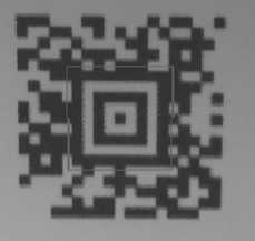
Fig. 3. Bullseye normalization: (a) input image I; (b) normalized image J. Red color denotes meta-information layer
a)

b)
Fig. 4. Sample of (a) "ideal" and (b) real Aztec Code matrices. Gray color on (a) – meta-information layer; red color on (b) – corresponding modules on real symbol image; green color – the first module of meta-information layer
After normalization, we start our spiral segmentation process directly from position ps = (M. x,M. у + 1) E R, where M is the location of the first ML layer's module position (Fig. 4). This position ps corresponds to the first unfilled module in R. We determine initial position for pj transforming this position via the perspective transform T. The spiral expands clockwise.
Each r E R element finds its corresponding p = (x, y) and brightness value v in J. After N steps, R is complete, and its v values are passed further to an Aztec decoder [2]. Pseudo-code listing 1 outlines this scheme.
Algorithm 1. The proposed segmentation scheme
Data: grayscale image I, QB , Mslze
Result: intensity matrix R. v
1. J,T ^ NormalizeImage(I,QB,Msize) 2. ML ^ DetermineModeMessageLayer(J) 3. Mmsg ^ ExtractModeMessage(ML) 4. N,E ^ DecodeModeMessage(Mmsg) 5. R ^ Allocate(E) 6. R ^ FillPredefinedModules(R) 7. pR ^ GetFirstUnfilledModule(R) 8. Pj ^ t(Pr) 9. for step in {1, , N} do 10. pB ^ MakeSpiralStepInR(pR,step) 11. pj, v ^ MakeSpiralStepInJ(pj, step, R) 12. R[pR]^(pj, v} 13. end 14. return R. v
The most intriguing part of the listing 1 is the MakeSpiralStepInJ procedure which is illustrated with Fig. 5. It consists of three stages:
-
1. Employ a spiral traversal algorithm within the J coordinate system, utilizing the established positions stored in R, to obtain a preliminary estimation of the next module center location denoted as Z.
-
2. Determine Y - the refined location of module center in the local neighborhood ^ based of the original Z evaluation.
3. Finally, determine the color of K’s position by analyzing its neighboring pixels. Let's consider every stage in more details.
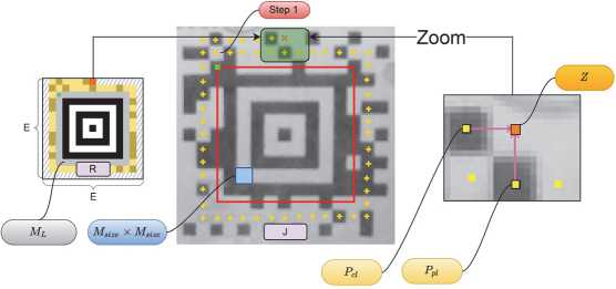
Fig. 5. Spiral segmentation process
Initial assessment of the next module position. Spiral scanning involves two distinct types of movement: linear progression and rotation by 90 degrees. Estimating the next module's position requires considering both.
For linear movement, the i-th step in the image J uniquely defines two neighboring modules, PCL (on the current layer) and PPL (on the previous layer) (see zoomed part of Fig. 5). The estimated position Z, uses x-coordinate of PCL and y-coordinate of PPL , yielding zx and zy.
For rotational movement, only one adjacent module PA exists. We calculate Z (x , y) by adding v to this PA module's center, thus, Z = PA + v. The v depends on the rotation’s direction: (MS[ze ,0) for right, (0, MS[ze ) for lower-right, (-MSize, 0) for lower-left, and (0, -MSize ) for upper-left.
The grid of the symbol may have irregular deformations, potentially leading to an imprecise prediction, and that is why this initial estimation requires further refinement or correction.
Module position correction. Let us consider the square neighborhood P of the size D X D of pixels at the center of the primary estimation Z. Let p(-) represent the evaluation function for assessing the score of any given position. Then, for each position q E P we calculate its evaluation score p(q). We choose the position qopt, which minimizes the value of p(-), thus, qopt = arg minqEDxD p(q). Hence, the used strategy is greedy [22] and results in Y = qopt.
The most intriguing question here is how to define position score assessing pQ). We define it using three internal scores, stored into matrices S^ S2, S3, all of size D X D. Then we represent this correction step as finding the smallest element within the Hadamard product of these three matrices, therefore, p(-) = Sr ° S2 ° S3. The initial position Z is shifted according to the obtained elements coordinates.
The first score, p^O or "shift score", just measures the L2 distance from the initial position Z(x, y) to previously located module centers PCL and PPL (or PA for corner modules) and stores it into Sr matrix.
The second one, p2(-) or "gradient score", penalizes module centers on high-gradient pixels, which typically lie on edges between modules. Its score matrix S2 is constructed by evaluating each candidate point q(x, y) E P as follows:
-
1. Extract a horizontal cross-section of length 5 ■ MS[ze centered on q(x, y) from the image.
-
2. Extract a vertical cross-section of length 5 ■ MS[ze centered on q(x, y).
-
3. Compute the sum of absolute gradient values for each cross-section, resulting in Lx (for the row) and Ly (for the column).
-
3. Experiments and discussion
The corresponding matrix element is then given by: S2(x,y) = (Lx + 1) ■ (Ly + 1), where a unit is added to each term to avoid zero-valued scores. The lower is the value, the better is the score.
Finally, the p3O or "variance score" assesses local image brightness variation. For a 3x3 module window W centered on a point q(x, y) E P, the brightness variance vark is calculated for each module wk E W. The sum of these values defines the element S3(x,y) of the brightness variance matrix: S3(x,y) = Xk=i vark . The lower is the value, the better is the score.
Module color evaluation. Selection of the color determination method for the module may vary a lot. To exemplify, compute the average intensity across a small neighborhood of Y and compare this value to a predefined threshold T. This method was employed in this study.
This approach offers several advantages, such as skipping the initial barcode binarization step and the need to detect its symbol borders, unlike the corner-based approach detailed in [17]. This makes it particularly useful when the symbol's edges are slightly cropped. Its ability to analyze pixel neighborhoods is well-suited for adaptive image processing. Moreover, because each barcode module location is dynamically determined based on previously identified modules, our method can recognize Aztec codes with irregular grid structures.
In this section, we evaluate the proposed method's accuracy using Aztec images from CoBRA-CYL-AZ dataset, generated by the CoBRA framework. This dataset contains images of several types of Aztec: 1) Aztec Code, 2) Aztec
Compact, 3) cropped Aztec Compact. This enables assessment of the proposed method’s performance across a range of Aztec types and recognition difficulty levels. Each code in the CoBRA-CYL-AZ stores the message "CoBRA" repeated several times. The error correction level of generated codes is set to the recommended 23 % of barcode symbol capacity plus 3 additional codewords which is a common practice. Aztec Code images include 5 original codes with number of modules along each side: 19, 23, 27, 33, 37. Both non-cropped and cropped Aztec Compact codes include 4 original codes with number of modules along each side: 15, 19, 23, 27.
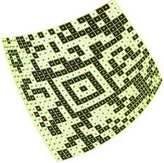
Curved Aztec codes are applied on cylindrical surfaces with various radius of circle at the base. These codes are rotated to different values on the applied surface (0, 15, 30) and rendered with single field of view (45) to produce various curvature distortions (Fig. 7).
a)


c)

Fig. 6. Curved Aztec Compact codes rotated on (a) 0, (b) 15, (c) 30
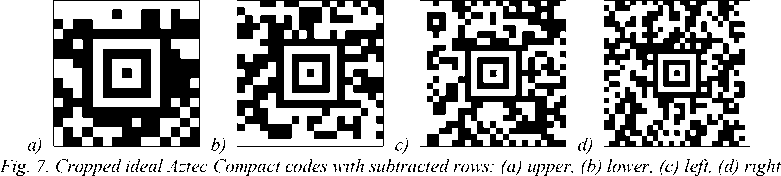
The images of cropped Aztec Compact codes are obtained from the original ideal Aztec Compact images by subtracting a single row of modules from either of matrix side (Figure 8). We subtracted rows from the following matrix sides according to the number of modules in Aztec Compact: upper (15), lower (19), left (23), right (27).
Each Aztec code is captured by a virtual camera from 5×5 points of view on a plane grid in front of the code during the 3D rendering. The images are rendered with the 960 × 1280 resolution. Images with small sized barcode modules are excluded from the dataset. To describe a size of barcode in pixels, we utilize the well-known pixels per module (PPM) measure. We aggregated the PPM values of each barcode of the three Aztec types. The resulting dataset contains images of barcodes with the following median values of PPM: 9.6 for the subset of Aztec Code images and 12.6 for Aztec Compact and cropped Aztec Compact images respectively.
We utilized the synthesized CoBRA-CYL-AZ dataset to evaluate the scanning accuracy of curved and cropped Aztec Compact codes. The accuracy of barcode scanning is measured as accuracy = С / T , where C is the number of correctly decoded messages and T is the total number of messages. We compared the proposed method to popular Aztec scanners like ZXing (ver: 3.5.3), ZXing-cpp (ver: 2.3.0), and Dynamsoft (ver: 11.0.3000) described in more details in the ending of section 1. Each scanner is configured by default except to scan only the group of Aztec symbologies.
The scanning accuracy of different scanning solutions on specific subsets of the CoBRA-CYL-AZ is provided in the Tab. 1.
Tab. 1. The accuracy of scanning curved Aztec Compact codes from CoBRA-CYL-AZ with different scanning solutions.
Dataset contains subsets namely Aztec Code (Si), Aztec Compact (S 2 ), cropped Aztec Compact ( S3 ) having different: barcodes' rotation value ( R ), number of images (N)
|
Subset |
Accuracy , % |
|||||
|
s |
R |
N |
ZXing |
ZXing-cpp |
Dynamsoft |
Our |
|
0 |
914 |
7.00 |
9.19 |
15.10 |
42.34 |
|
|
S i |
15 |
902 |
0.00 |
14.30 |
23.95 |
51.00 |
|
30 |
872 |
0.00 |
18.58 |
27.75 |
50.34 |
|
|
Average |
2.33 |
14.02 |
22.27 |
47.89 |
||
|
0 |
754 |
10.08 |
13.79 |
17.37 |
60.21 |
|
|
S 2 |
15 |
752 |
0.00 |
22.87 |
26.56 |
72.34 |
|
30 |
738 |
0.00 |
26.56 |
28.32 |
73.31 |
|
|
Average |
3.36 |
21.07 |
24.08 |
68.62 |
||
|
0 |
754 |
3.58 |
6.10 |
0.66 |
52.39 |
|
|
S3 |
15 |
752 |
0.00 |
12.50 |
0.27 |
65.16 |
|
30 |
738 |
0.00 |
20.19 |
0.14 |
66.67 |
|
|
Average |
1.19 |
12.93 |
0.36 |
61.41 |
||
|
Total Average |
2.33 |
15.83 |
15.93 |
58.56 |
||
The proposed algorithm allows to extract curved matrices, as well as to deal with violations of the barcode structure like cropped modules (see Fig. 8 a ). However, it may fail at the outer layers as demonstrated at Fig. 8 d . It may happen when the correction forces two layers too close together, and they repel each other according to the q1(-) score.
a)


c)
d)
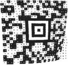
Fig. 8. Visualization of the spiral segmentation results: (a, b) input images with curved Aztec Compact codes, (c, d) estimated module positions in the normalized images
The proposed method was implemented using C + + language and was compiled with gcc. The measurements were done on the desktop computer with the following configuration: Intel Core i7-9700K 4.6 GHz, 16320 MB DDR4 SDRAM, Ubuntu 22.04 OS.
Our method shows the best accuracy in scanning both non-cropped (68.62 %) and cropped (61.41 %) curved Aztec Compact codes while outperforming the second most accurate scanner in both subsets respectively by 44.54% and 51.48 %. Though Dynamsoft has the second greatest accuracy on non-cropped subset, it is unable to scan cropped Aztec Compact codes as the average accuracy for this subset is less than 1 %. On the contrary, ZXing-cpp is able to scan both types of codes, but with less than 20% of accuracy on the average. Furthermore, ZXing-cpp with default scanning settings has shown to be a better solution than ZXing to scan Aztec codes. We also experimented with Aztec Code symbology scanning and achieved relatively close results to Aztec Compact taking into account the uneven distribution of images in the subsets.
As can be seen from the Tab. 1, the accuracy of scanning grows with the Aztec codes being rotated over the cylindrical surface. That means the codes with greater rotation values are less curved on the sides and distorted from some points of view on the camera grid.
We measured the time performance of scanning Aztec Compact codes from the CoBRA-CYL-AZ dataset on the desktop computer which characteristics are described previously in this section. The median value of scanning time equals 73 milliseconds.
To test our spiral segmentation method's ability to scan real-world Compact Aztec codes, we collected a small dataset Photo-AZ-CC comprising 201 photos of damaged, cropped, curved and crumpled symbols. We utilized several smartphones running under two major mobile operation systems Android and iOS: Apple iPhone 15 Pro, Samsung Galaxy A55 5G, Google Pixel 7, Xiaomi 14 Ultra. The smallest resolution of captured images is 720 X 1280. Other images have higher resolution which is defaulted to the used camera settings. The persons who collected images were instructed to take a snapshot in such a way that its area occupies a significant part of the frame and is located not far away from the image center. Additionally, they had to check whether a cropped barcode is scannable or not before it was placed on the curved surface. There were no other instructions in order to achieve greater photo variability of originally scannable barcodes while preventing them from being small-sized.
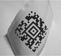
Some examples from this dataset are presented in Fig. 9. Tab. 2 shows that our method is applicable with the real photos.
a)

b)

Fig. 9. Samples of real-world Aztec codes from the Photo-AZ-CC dataset
c)

While our spiral segmentation approach works for all types Aztec codes, we propose to use it only for the Aztec Compact codes and apply a method from the paper [5] for full Aztec codes.
Conclusion
The importance of barcode scanning is growing as barcodes find wider applications and are increasingly scanned by ordinary smartphone users. This paper presents a method for Aztec symbol matrix segmentation from images where they are applied to curved surfaces and potentially slightly cropped. It avoids pre-binarization stage and relies on conventional adaptive image processing techniques to handle non-planar cases. It outperforms popular open-source solutions like ZXing , ZXing-cpp and proprietary ones allowing the demo access for testing purposes like Dynamsoft with a noticeable gap in the scanning accuracy. To reveal that, we introduce a new dataset CoBRA-CYL-AZ [5] and evaluate the accuracy of the main solutions. The dataset CoBRA-CYL-AZ is published and its latest version can be downloaded via the link: The average accuracy of our scanning method is more than 3 times greater comparing to the second most accurate of the reviewed Aztec scanners. Furthermore, the proposed method can scan distorted and damaged Aztec Compact codes, which lack the timing patterns required by other methods, making it applicable where previous approaches fail.
Tab. 2. The accuracy of scanning real photos of Aztec Compact codes with the proposed spiral segmentation method. The subsets of the dataset with real photos differ in: Aztec Compact code side dimension (D), number of images (N)
|
Subset |
Accuracy , % |
|
|
D |
N |
Our |
|
15 |
43 |
39.53 |
|
19 |
57 |
54.39 |
|
23 |
34 |
70.59 |
|
27 |
34 |
50.75 |
|
Average |
53.82 |
|
The spiral segmentation method takes 73 milliseconds as a median value of scanning a single image from the CoBRA-CYL-AZ dataset. We confirm the applicability of the proposed method on a small dataset of Aztec Compact photos. The proposed method has proven itself effective to be implemented in mobile scanning applications and improve the overall user experience of scanning barcodes in uncontrolled environment and within high-traffic areas where accuracy and time of scanning value the most.
