An automatic device for measuring resistivity of the silicon four-point probe method

Author: Vladimirov V.M., Shepov V.N., Grinin E.F., Sergiy M.E.
Journal: Сибирский аэрокосмический журнал @vestnik-sibsau
Section: Математика, механика, информатика
Article in issue: 5 (26), 2009.
Free access
An automatic device for measuring the resistivity of single-crystalline silicon by means of the four-point probe method has been developed.
Automatic device, single-crystalline silicon, resistivity, four-point probe method
Short address: https://sciup.org/148176089
IDR: 148176089
Text of the scientific article An automatic device for measuring resistivity of the silicon four-point probe method
The Rometer device has been developed based on standards, methods, and requirements of equipment and techniques for developing measuring devices and methods. It is designed for automatic measurement of single crystalline silicon resistivity by the four-point probe method.
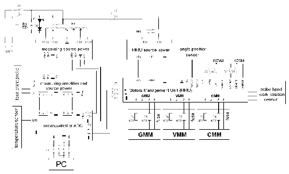
The device . In figure 1 – a photo of the device is shown, in figure 2 – its block diagram.
The device consists out of following functional elements: afour-pointprobewithin-lineplacedprobes; twopowersupplies (the first – supplies the measuring unit, and the second – supplies the stepper motor); electrical current source for probe head outside probes; two microcontrollers (the first – for work management of the measuring unit, the second – for the management of the displacement test desk and probe head); an Analog-to-Digital Converter (ADC); an analogue resistive equivalents; a measuring amplifier; a temperature sensor; the Motors Management Unit (MMU); a test desk angle position sensor; a probe head work position censor.
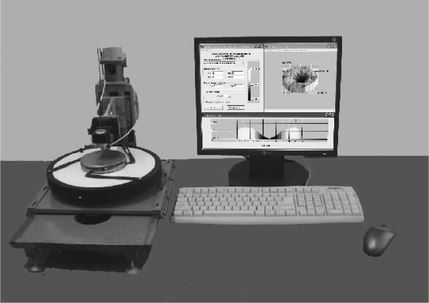
Fig. 1. Structure of the Rometer device
The probe head (in the Rometer device a Jandel Engineering ltd probe head is used; the distance between the probes is 1.59 mm) it provides direct current of the specify value on sample through outer probes, and measuring voltage on inner probes, which are connected to a measuring amplifier. The analog signal comes from the amplifier exit to an 18-digit ADC MAX132 input, and transforming into a digital code, then – to ATMEGA8 microcontroller input, and then – into the personal computer. The power supply for measuring the unit gives stable voltage of +15 V and –15 V for measuring amplifier work, ADC and also its gives +5 V for first microcontroller and the temperature sensor. The second power supply gives voltage of +10 V for the stepper motors and +5 V for the second microcontroller ATMEGA8 and MMU. Power supplies are screened to decrease sound influence on the measuring amplifier. The current source for probe head is adapted for generating currents with discrete selection current strength of 0.25 µA, 2.5 µA, 25 µA, 250 µA, 2.5mA, 25 mA, and 100 mA with a possibility of polarity change. The current value is set for a measuring value range in accordance with SEMI MF84 [1]. In the measuring mode the current flows through samples between outer probes of four-point probe head; in the calibration mode the current flows to the analogue resistor equivalents. Theses are 7 10,000 Ohm, 1,000 Ohm, 100 Ohm, 10Ohm, 1 Ohm, 0.1 Ohm, 0.01 Ohm precision resistors. These resistors are connected to current source by transition resistors, which simulate transition resistance between probe pins and silicon sample.
Silicon wafers and single crystalline silicon ingots temperature control is provided by the DS1820 temperature sensor. Its output signal comes to the first microcontroller. The second command microcontroller MMU gives necessary impulse sequences to the stepper motors for forward and reverse rotation. In the дши-200-1 stepper motor is used in the device. The angle position sensor ЛИР458А monitors the angle of the moving part test desk from the probe head. The sensor output digital code signal comes to the second microcontroller. Limit switches of horizontal and vertical displacement provide control signals to the second microcontroller if the four-point probe or the test desk position reaches the agreed value. The Optron sensor working position of the probe head АОТ 147-А produces a control signal in the second microcontroller, if the probes pressure at sample makes a value recommended in [1].
The manager program . The working control program of the device consists from four subprograms, which allow the following: the measurement of silicon resistivity in one point with user times defined; the measurement of resistivity in 6 points with accordance to [2] (variant B); creating a measurement resistivity map with accordance to [3]; measurement resistivity non-standard volumetric samples. The manager program in an automatic mode allows the following: calibrating with analogue equivalents; measuring silicon wafer or ingot thickness; setting a necessary current value in outer probes of the four-point probe head; measuring potentials between inner probes; calculating resistivity with accordance to [1] and considering correctional factors (geometrical, thermal). In the program window the measuring protocol, which provides control resistivity value during measurements can be seen.
Operating the device . After the manager program has been started, the memory management unit (MMU) panel gives a signal to the horizontal, vertical and rotation stepper motors for setting the test desk in a default position. A sample of single crystalline silicon is fixed so that its center coincides with the probe head center. Then, the automatic calibration is performed. To do this, the probe head is disconnected from the power supply and measuring
amplifier by a command from the manager program and an analogue equivalent is connected instead. The electrical current with a set value is launched through the analogue equivalent and the microcontroller indicates voltage decrease with a change in the polarity. After that, the calibration power supply, measuring amplifier and probe head is automatically connected. Then, the vertical manipulator moves the probe head down on the sample until the probes touch its surface. The resistivity is measured automatically, in compliance with the selected subprogram and temperature corrections [1].
In figure 3 the measurement result is shown. A sample single-crystalline silicon wafer had been synthesized by the Czochralski method. The manager program makes it possible to show resistivity in any point of the 3D figure and shows the sectional distribution of resistivity.
General technical specification. The range of electrical resistivity measurements is from 0.001 to 10,000 Ohm ■ cm. The range of the allowed relative error in resistivity measurement is within 0.001 - 0,01 Ohm ■ cm = ±3 %; 0,011 -10,000 Ohm ■ cm = ±2 %. The diameter of the silicon wafer (slices) varies from 10 to 200 mm, with the thickness being from 0.1 to 30 mm. The overall dimensions of the device are 560 x 320 x 410 mm. The weight is 25 kg.
Thus, the automatic measuring device for single crystalline, slices, and wafer silicon resistivity is similar to the best foreign constructions according to the technical characteristics. Tests of major relative errors, defined in the certification, do not exceed the value [1–4].
The device was certified in 2007. According to its certificate the ROMETR device for silicon resistivity measuring was registered in the State Catalog of Measuring Devices under the index 35567-07 and can be exploited in the Russian Federation.
