An Efficient Deblocking Filter Algorithm for Reduction of Blocking Artifacts in HEVC Standard

Author: Hojatallah Karimzadeh, Mohammadreza Ramezanpour
Journal: International Journal of Image, Graphics and Signal Processing(IJIGSP) @ijigsp
Article in issue: 11 vol.8, 2016.
Free access
The international standard of High Efficiency Video Coding (HEVC) improves the compression ratio over %50 compared with previous standards such as H264/AVC which maintain the same perceptual quality. HEVC has achieved significant coding efficiency improvement beyond existing video coding standard by employing several new coding tools. Deblocking filter, Adaptive Loop Filter (ALF) and Sample Adaptive Offset (SAO) are currently introduced for the HEVC standard. The deblocking filter detects the artifacts at the coded block boundaries and attenuates them by employing a selected filter. However, it was shown that the HEVC encoder may produce visible block artifacts on some sequences. In this paper, we propose an efficient deblocking filter to reduce block artifacts. The simulation results indicate that the maximum increase Peak signal-to-noise ratio (PSNR) of the proposed method is 0.09db, comparing to other deblocking filter algorithm.
HEVC, Deblocking filter, Artifacts, Image quality
Short address: https://sciup.org/15014083
IDR: 15014083
Text of the scientific article An Efficient Deblocking Filter Algorithm for Reduction of Blocking Artifacts in HEVC Standard
Published Online November 2016 in MECS
Similar to the previous video coding standards, such as H.264/AVC, the HEVC standard is based on a hybrid coding scheme using block-based prediction and transform coding. Several new coding structures have been introduced in HEVC: coding unit (CU), prediction unit (PU) and transform unit (TU). The CU is the basic unit of region splitting used for intra/inter coding. It can be split from the largest coding unit (LCU, can be as large as 64×64) into the smallest coding unit (8×8). Coupled with CU, PU carries the information related to the prediction processes. TU is used for transformation and quantization, and it depends on PU partitioning modes [2].
Despite these advantages, due to quantization as well as motion compensation, some certain distinct parts called block artifacts are created in the image [3] [4]. To eliminate such parts, a deblocking filter should be used [5] .
The deblocking filter detects the artifacts at the coded block boundaries and attenuates them by applying a selected filter [6]. Compared to the H.264/AVC deblocking filter, the HEVC deblocking filter has lower computational complexity and better parallel processing capabilities while still achieving significant reduction of the visual artifacts [7]. The deblocking filter in HEVC is designed to improve the subjective quality while reducing the complexity. The latter consideration is important since the deblocking filter of the H.264/AVC standard constitutes a significant part of the decoder complexity. As a result, the HEVC deblocking filter is less complex than the H.264/AVC deblocking filter, while still having the capability to improve the subjective and objective quality [8].
The main difficulty when designing a deblocking filter is to decide whether or not to filter a particular block boundary, and to decide on the filtering strength to be applied. Excessive filtering may result in unnecessary smoothing of the picture details, whereas lack of filtering may cause a loss in some blocking artifacts effects, which would reduce the subjective quality [9].
In the HEVC standard, the size of prediction blocks can vary from 4×4 to 64×64. Large prediction blocks are more suitable for coding of large homogenous regions, and small prediction blocks are employed where the spatial details differ in small regions. As a result, in images with complex backgrounds, 4×4 blocks are selected while in the HEVC deblocking filter, 8×8 filters are used. The HEVC encoder ignores this fact, and causes that it can not attenuates block artifacts in sequence with more details [10].
In this paper, we propose a simple and efficient postprocessing algorithm to eliminate blocking artifacts for standard HEVC in the Discrete Cosine Transform (DCT) domain, which first, measures the activity of block boundary between adjacent horizontal and vertical blocks, and then splits it into smooth, Non-smooth and intermediate areas.
The rest of this article is organized as follows: in section II , related works are received, Section Ш provides a detailed description of the proposed method, simulation results are discussed in Section IV, followed by conclusion in section V.
-
II. Related Works
The deblocking filter detects the artifacts at the coded block boundaries and attenuates them by applying a selected filter. This is one of the most annoying artifacts in video and image compression coding [11].
The deblocking filter is applied to all samples adjacent to a PU or TU boundary except the case when the boundary is also a picture boundary, or when deblocking is disabled across slice or tile boundaries. The processing order is defined as horizontal filtering of vertical edges for the entire picture first, followed by vertical filtering for horizontal edges. The overall processing flow of deblocking filter is illustrated in Fig.1. At first, we make decision that whether the current boundary is a boundary of CU, PU or TU. If not, the filtering processing should not be applied to the current boundary. Secondly, boundary strength (BS) reflects how strong the filtering should be for the boundary,.the value of this parameter is an integer ranging from 0 to 2. Thirdly, threshold values β and tC are used for filter on/off decision, strong/weak filter selection and the process of the filtering are derived based on the Quantization parameter of block [10].
Fig.1 indicates the flowchart of the main deblocking filter algorithm.
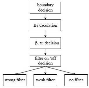
Fig.1. Overall processing flow of deblocking filter [10]
In order to improve the quality of the reconstructed image and video, several deblocking algorithms have been proposed.
In [12] an approach for reducing artifact was presented which is based on two types of filters i.e Fuzzy Impulse Artifact Detection and Reduction Method (FIDRM) and
Noise Adaptive Fuzzy Switching Median filters. These filters are based on fuzzy rules. The main feature of FIDRM filter is that it leaves the noise free pixels unchanged. Experimental results showed the feasibility of the new algorithm. Numerical measures, such as PSNR, and visual quality revealed convincing results for grayscale images. The proposed approach can be used in many mobile devices having limted storage and bandwidth and as a result they suffer from blocking artifacts.
Palaparthi and Srivastava [13] , proposed a simple deblocking algorithm to reduce blocking artifacts from DCT coded images. They applied a simplified method for measuring blocking effects and these artifacts can be successfully alleviated by modifying pixel values across the block boundaries. The block boundary activity facilitated measuring the blocking artifacts between adjacent blocks. This algorithm took less time to remove blocking artifacts. It is clear from the plot that there was an increase in PSNR value of Lena and Gold hill images with the use of the proposed method over other methods.
In [14], a novel deblocking filter algorithm was proposed for video real time encoding or decoding in H.264/AVC. The first optimization step copied one BS value of line of pixels to that of the other three line of pixels in the same 4x4 block for avoid repetitive calculations. The second optimization step skipped some unnecessary edges for reduce waste time to detect BS values on these edges.
Wei and BingChao [10] proposed a novel and efficient deblocking filter algorithm based on the improved boundary decision method. Prediction unit or transform unit boundaries can be selected to filter all boundaries of 8×8 block according to the Depth, Transform Index and Partition Size information from all 8×8 block.
Eldeken, and Salama [15], the deblocking filter process of the HEVC standard modified. The modification was based on determining better offset parameters in the filtering process to remove the blocking artifacts on the decoded video sequences. The proposed approach used an adaptive Deblocking filter providing an improvement in terms of rate distortion performance without changing the compression ratio.
Most techniques of decreasing Artifacts in the removal time blurred the details of the images. Deblocking filter identified the effects of program execution in the boundary of coding blocks and regulated them by applying their selected filter [16].
Deblocking filter in HEVC had lower computational complexities compared with the deblocking filter H.264/AVC and had better parallel processing capabilities while causing considerable decrease in the Artifacts of the images. In this paper, an efficient deblocking filter algorithm of modified HEVC is introduced on 4×4 blocks and the results of the tests show that the introduced algorithm has dramatic improvement in the efficiency of coding and the capabilities of better parallel processing along with the same bitrate and operation compared with the previous algorithms [17] [18].
-
III. The Proposed Method
The blocking artifact resulted from the discontinuity created at 8×8 block boundaries is one of the main defects of block-based transform coding as blocks are independently compressed and decompressed [19]. The size of prediction blocks for HEVC standard varies from 4×4 and 64×64. Large prediction blocks are used for smooth parts of the image and smaller ones are for parts with great details. Therefore, it can be said that in images with complex backgrounds, the ratio of 4×4 blocks to the size of blocks are higher than that of the others. In the main algorithm of HEVC deblocking filter, 8×8 filters are used [20], whereas in our proposed method, all 4×4 edges are processed which is regarded as the advantage of this method over HEVC standard.
Assume that blocking artifacts between the two 8×8 horizontal blocks, a1 and a2, are respectively considered with mean values Y1 and Y2 in the DCT domain. In this case, a new block S is formed from the right half of S1 and left half of S2, as shown in Fig.2.
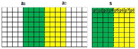
Fig.2. The image of the newly transferred block
Using the activity of the block boundary, discontinuities between adjacent blocks are divided into three groups of smooth, Non-smooth, and intermediate areas. The blocking artifacts in smooth and Non-smooth areas are eliminated by replacing a number of coefficients. These areas are classified using threshold values (T1, T2). These threshold values were measured in experiments [13]. The deblocking filter process is used in order to reduce blocking artifacts in the post-processing DCT domain. Blocking artifacts are recognized by using the activity of the block boundary. This activity is measured by analyzing pixel values between two adjacent horizontal or vertical blocks. In order to reduce blocking artifacts between adjacent horizontal blocks, changes in pixel values along the activity boundary is called horizontal block boundary shown by Z h (p) which is measured by using the equation (1).
Z ( p ) = ZZ । P jkk - P j+vk i (1)
j = 1 k = 1
Sixteen pixels are entered into the calculations on each side of the boundary for measuring the activity along the block boundary, thus, the total values of thirty-two pixels is used to measure the activity along the block boundaries. Moreover, the boundary activity of the vertical block Z v (p) is measured according to equation (2) as shown in Fig.3.
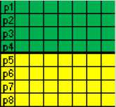
Fig.3. The image of the newly transferred vertical block
The boundary activity of the vertical block is measured as follows:
Z v ( p ) = ZZ i p j , k - P j + 1, k i (2)
j = 1 k = 1
Based on the value of Z(p), all blocks are divided into three areas so that blocking artifacts can be reduced. The horizontal reduction of the blocking artifact is expressed in the following. The vertical filtering is also the same. The experiments showed that the threshold values T1 and T2, respectively equal to 1 and 4, results in the good discrimination of areas. Correcting pixel values along the block boundary depends on the area being filtered.
Fig.4 indicated the flowchart of the proposed algorithm.
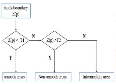
Fig.4. Flowchart algorithm of the proposed method
-
A. Smooth areas
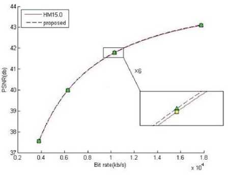
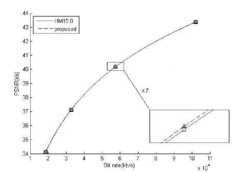
If two adjacent 8 × 8 blocks, a1 and a2, have the same horizontal frequency characteristics, then the block S can be considered as a smooth area and the boundary activity of the horizontal block meets the condition Z(p) Artifact = | (P3+P4) – (P5+P6) | (3) Table.1. Equations For Correct Pixels Of Smooth-Area row (P3+P4) < (P5+P6) (P3+P4) > (P5+P6) 1 P’2 = P2 + artifact/8 P’2 = P2 - artifact/8 2 P’3 = P3 + artifact/4 P’3 = P3 - artifact /4 3 P’4 = P4 + artifact/2 P’4 = P4 - artifact /2 4 P’5 = P5 - artifact /2 P’5 = P5 + artifact/2 5 P’6 = P6 - artifact /4 P’6 = P6 + artifact/4 6 P’7 = P7 - artifact /8 P’7 = P7 + artifact/8 P3, P4, P5, P6 are pixel values along the block boundary area. the corrected pixel values are included in table.1. For smooth areas, intensity values are almost constant in one block and it is only updating pixels close to block boundaries that results in the creation of other artifacts in the center of the block. In order to use less hardware in this method, instead of dividing the variable by 6 for Equations in rows 1 and 6 of table.1, according to the algorithm proposed by Kumar [13] for JPEG, we divide it by 8 since it can be implemented by shifting operations. B. Non-smooth areas If two adjacent 8 × 8 blocks, a1 and a2, have the same vertical frequency characteristics, then the block S can be considered a Non-smooth area and the boundary activity of the vertical block meets the condition Z(p)> T2. The block boundary activity is greater in this area due to the different frequency characteristic. Therefore, pixel values are corrected and presented in table.2. Table.2. Equations for Correct Pixels Of Non-Smooth Area row (P3+P4) < (P5+P6) (P3+P4) > (P5+P6) 1 P’3 = P3 + artifact /4 P’3 = P3 - artifact /4 2 P’4 = P4 + artifact /2 P’4 = P4 - artifact /2 3 P’5 = P5 - artifact /2 P’5 = P5 + artifact /2 4 P’6 = P6 - artifact /4 P’6 = P6 + artifact /4 C. Intermediate areas If the two adjacent blocks a1 and a2 are placed between smooth and Non-smooth areas, then the block S can be considered an intermediate area, and the boundary activity of the vertical block meets the condition T1 Blocking artifacts with minimum data loss are reduced due to the use of this low pass filter at each side of the block boundary. In order to reduce discontinuities between adjacent blocks in the horizontal direction, all the above steps are repeated by combining two adjacent vertical blocks. This filtering process can eliminate the blocking artifact and also has a low computational cost. An algorithm similar to the above algorithm is applied for artifacts of the vertical block boundary in the vertical direction. Fig.5 shows the modification of pixel values after applying the deblocking filter algorithm for the block boundary along the blocks. Fig.5. (a) the existence of artifacts at the block boundary, (b) eliminating artifacts of the block boundary The poposed method is implemented by the HEVC test model, HM 15.0. The performance of the proposed deblocking method is illustrated under different bitrate based on the resulting subjective image quality and also objective measurement in PSNR. Here, the ratio of peak signals to noise is equal to the quality of decoded images and PSNR is defined as (4). 255 2 PSNR = 10 x log —У-------dbb (4) 10 Nt=1(Xt -Y,)2 Where Xi and Yi are the iTH position pixel values of the original and reconstructed images, respectively. Here, N is the total number of pixels in the image. The coding efficiency of the proposed method is measured using the Bjontegaard Distortion-rate (BD-rate). Moreover, the encoding time is used to compare the computational complexity of the proposed method with the reference software. The encoding time is defined in equation (5). TimeHM 15.0 Time proposed DT =----------——x100 imeHm15.0 In order to evaluate the coding efficiency and computational complexity of the proposed method, 9 test sequences from class A to Class E are used with different QP of 22, 27, 32, and 37 that proposed by the JCT-VC. All the frames were coded in form of I. For each video, 50 frames were coded using the main structure. The coding efficiency of the proposed method compared with the HEVC test model are tabulated in table 3 to 6. sequence are unchanged. Table.5 The Image Quality Of The Proposed Method Compared To The HEVC Standard Reference Software With Quantization 32 Table.3 The Image Quality Of The Proposed Method Compared To The HEVC Standard With Quantization 22 PSNR(db) Bit-rate (Kbps) ∆T Test sequences Ancho r Propose d method Anchor Proposed method [% ] Basketballpas s 42.58 42.59 5414 5414 0.0 Blowingbubbl es 41.08 41.16 9444.13 9444.13 0.1 Partyscene 41.08 41.14 50999.23 50999.23 0.1 Basketballdril l 41.75 41.77 20143.41 20143.41 0.0 Fourpeople 43.84 43.85 30113.87 30113.87 0.0 Kimono1 43.09 43.11 17773.44 17773.44 0.0 Parkscene 41.59 41.62 48778.09 48778.09 0.0 Peopleonstree t 43.25 43.27 103663.22 103663.2 2 0.0 Traffic 43.36 43.37 102034.65 102034.6 5 0.0 Table 3 shows the coding efficiency of the proposed method compared with the HEVC test model with QP=22. It can be seen bitrate remain unchanged while image quality increase in PSNR. The maximum PSNR increase is 0.08db in Blowingbubbles, whereas the encoding time increase 0.1%. The minimum PSNR increase is 0.01db in Traffic sequence whereas the encoding time is unchanged. Table.4 The Image Quality Of The Proposed Method Compared To The HEVC Standard With Quantization 27 PSNR(db) Bit-rate (Kbps) ∆T Test sequences Anchor Proposed method Anchor Proposed method [% ] Basketballpass 39.07 39.09 3204.84 3204.84 0.0 Blowingbubble s 37.08 37.17 5590.37 5590.37 0.1 Partyscene 36.61 36.66 32368.10 32368.10 0.0 Basketballdrill 38.39 38.42 10846.63 10846.63 0.0 Fourpeople 41.29 41.31 18687.36 18687.36 0.0 Kimono1 41.77 41.79 10288.12 10288.12 0.0 Parkscene 38.73 38.75 26328.71 26328.71 0.0 Peopleonstreet 39.81 39.84 60239.03 60239.03 0.0 Traffic 40.17 40.17 57460.99 57460.99 0.0 Table 4 shows the coding efficiency of the proposed method compared with the HEVC test model with QP=27. It can be seen bitrate remain unchanged while image quality increase in PSNR. The maximum PSNR increase is 0.09db in Blowingbubbles, whereas the encoding time increase 0.1%. PSNR and encoding time in Traffic PSNR(db) Bit-rate (Kbps) ∆T Test sequences Anchor Proposed method Anchor Proposed method [%] Basketballpass 35.62 35.63 1804.11 1804.11 0.0 Blowingbubbles 33.48 33.53 3101.09 3101.09 0.1 Partyscene 32.57 32.62 19538.83 19538.83 0.1 Basketballdrill 35.41 35.45 5816.53 5816.53 0.0 Fourpeople 38.38 38.41 11545.92 11545.92 0.0 Kimono1 39.97 39.99 6272.25 6272.25 0.0 Parkscene 35.87 35.90 13751.49 13751.49 0.0 Peopleonstreet 36.69 36.71 34227.60 34227.60 0.0 Traffic 37.11 37.12 32778.38 32778.38 0.1 Table 5 shows the coding efficiency of the proposed method compared with the HEVC test model with QP=32. It can be seen bitrate remain unchanged while image quality increase in PSNR. The maximum PSNR increase is 0.05db in Blowingbubbles and Partyscence, whereas the encoding time increase 0.1%. The minimum PSNR increase is 0.01db in Traffic and Bsketballpas sequences whereas the encoding time in Traffic increase 0.1% and the encoding time in Bsketballpas is unchanged.. Table.6 The Image Quality Of The Proposed Method Compared To The HEVC Standard Reference Software With Quantization 37 PSNR(db) Bit-rate (Kbps) ∆T Test sequences Anchor Proposed method Anchor Proposed method [%] Basketballpass 32.41 32.44 990.80 990.80 0.0 Blowingbubbles 30.22 30.27 1641.32 1641.32 0.1 Partyscene 28.77 28.80 10816.45 10816.45 0.1 Basketballdrill 32.87 32.89 3199.75 3199.75 0.0 Fourpeople 35.23 35.25 6996.14 6996.14 0.0 Kimono1 37.54 37.57 3798.50 3798.50 0.0 Parkscene 33.09 33.13 6802.91 6802.91 0.0 Peopleonstreet 33.86 33.90 19977.36 19977.36 0.0 Traffic 34.10 34.12 18584.86 18584.86 0.1 Table 6 shows the coding efficiency of the proposed method compared with the HEVC test model with QP=37. It can be seen bitrate remain unchanged while image quality increase in PSNR. The maximum PSNR increase is 0.05db in Blowingbubbles, whereas the encoding time increase 0.1%. The minimum PSNR increase is 0.01db in Traffic, Fourpeople and Basketballdrill sequences whereas the encoding time is unchanged for them. It can be concluded from the results obtained from the simulation that the proposed method significantly increases image quality as compared to the reference method. However, time is minimally increased as we are working on 4 × 4 blocks, unlike 8 × 8 blocks used in the reference method. Fig.5 indicates the RD-curve of the proposed method compared to the reference software for two videos kimono1 and Traffic video with horizontal axis of this bit rate. PSNR is also its vertical axis. In order to observe more accurate behavior of RD curves, a part of the diagram is magnified, the amount of which is written on each form. Moreover, we predict the bit rate and similar quantization of PSNR value in our proposed method to be more, resulting in higher image quality. (a) (b) Fig.5 Comparison of the distortion-rate diagrams of the proposed method and the HEVC reference software for: (a) kimono (b) Traffic As Table.7 reveals, the proposed method is able to reduce bit rate while having the same image quality comparing to the reference software. We applied a simple method to measure blocking artifacts and we proved that these artifacts can be successfully reduced by modifying pixel values across HEVC block boundaries. The activity of the block boundary simply measures blocking artifacts between adjacent blocks. According to the output tables and the results of the experiments, there clearly is an increase in the PSNR value of video images using the proposed method comparing to other methods. Moreover, the experimental results show that the proposed method performs better in terms of visual quality than the existing methods and also reduces artifacts of video images. Filters with the size 8 × 8 are used in the main algorithm of HEVC deblocking filter, while all 4 × 4 edges are processed in our proposed method and therefore, the image quality is higher, which indicates the superiority of our method comparing to the HEVC standard reference method. Moreover, to use less hardware in this method, instead of dividing the variable by 6, we divide it by 8 since it can be implemented by shifting operations. [1] D. Flynn, M. Naccari, K. Sharman, C. Rosewarne, J. Sole, G. J. Sullivan, T. Suzuki, "High Efficiency Video Coding (HEVC) Range Extensions text specification," 2014. [2] K. McCann, B. Bross, W. Han, I. Kim, K. Sugimoto and G. Sullivan, "High efficiency video coding (HEVC) test model 12 (HM 12) encoder description," JCT-VC, Doc. JCTVC N, vol. 1002, 2013. [3] Alan W.-C. Liew, Member, IEEE, Hong Yan, "Blocking Artifacts Suppression in Block-Coded Images Using Overcomplete Wavelet Representation," in IEEE TRANSACTIONS ON CIRCUITS AND SYSTEMS FOR VIDEO TECHNOLOGY, 2004. Table.7 The Efficiency Of Encoding And Encoding Time Of The Proposed Method Compared To The Reference Software Hm15.0 In The Main Structure Test sequences BD-Rate ∆T % [%] Basketballpass -0.3 0 Blowingbubbles -1.3 0.1 Partyscene -0.6 0.1 Basketballdrill -0.6 0 Fourpeople -0.4 0 Kimono1 -0.6 0 Parkscene -0.6 0 Peopleonstreet -0.5 0 Traffic -0.1 0 Average -0.56 0.02 [4] T. Wiegand, G. J. Sullivan, G. Bjontegaard, A. Luthra, "Overview of the H.264/AVC Video Coding Standard," in IEEE Trans. on Circuits and Systems for Video Technology, 2003. [5] F. Bossen, B. Bross, IEEE, K. S¨uhring, D. Flynn, "HEVC Complexity and Implementation Analysis," in IEEE Transactions on circuit and systems for video technology, 2012. [6] Peter List, Anthony Joch, Jani Lainema, Gisle Bjontegaard,Marta Karczewicz, "Adaptive Deblocking Filter," in IEEE Transactions on Circuits and Systems for Video Technology, 2003. [7] G. J. Sullivan, J.-R. Ohm, W.-J. Han and T. Wiegand, "Overview of the high efficiency video coding (HEVC) standard," Circuits and Systems for Video Technology, IEEE Transactions on, vol. 22, no. 12, 2012. [8] Hao Chen, Ruimin Hu,Yuan Gao, "An Effective Method of Deblocking Filter for H. 264/Avc," in Communications and Information Technologies, 2007. ISCIT'07. International Symposium on, 2007. [9] Y. Luo, R.K Ward, "Removing the Blocking Artifacts of block based dct compressed images," in IEEE Trans. on Image process, 2003. [10] Kang Runlong, Zhou Wei, Huang Xiaodong,Dong BingChao, "An efficient deblocking filter algorithm for HEVC," in Signal and Information Processing (ChinaSIP), 2014 IEEE China Summit & International Conference on, 2014. [11] V. Srivastava, "A DCT based Algorithm for Artifacts Reduction from DCT coded Images," in Electronic Letters on Computer Vision and Image Analysis , 2009. [12] Sonia Malik, Rekha Saroha, and Rohit Anand, "A SIMPLE ALGORITHM FOR REDUCTION OF BLOCKING ARTIFACTS USING SAWS TECHNIQUE BASED ON FUZZY LOGIC," International Journal Of Computational Engineering Research, pp. 1097-1101, 2012. [13] Ramakrishna Palaparthi ,Vinay Kumar Srivastava, "A Simple Deblocking Method for Reduction of Blocking Artifacts," in Electrical, Electronics and Computer Science (SCEECS), 2012 IEEE Students' Conference on, 2012. [14] Yuan Li, Ning Han, Chen Chen, "A Novel Deblocking Filter Algorithm In H.264 for Real Time Implementation," in Third International Conference on Multimedia and Ubiquitous Engineering, 2009. [15] AF .Eldeken, AF; GI.Salama, "An Adaptive Deblocking Filter to Improve the Quality of the HEVC Standard," I.J. Image, Graphics and Signal Processing, vol. 7, pp. 9-15, February 2015. [16] Y. Yuan, I.-K. Kim, X. Zheng, LingzhiLiu, X. Cao, S. Lee, M.-S. Cheon, T. Lee, Y. He and J.-H. Park, "Quadtree Based Nonsquare Block Structure for Inter Frame Coding in High Efficiency Video Coding," in Circuits and Systems for Video Technology, IEEE Transactions on, 2012. [17] J.Vieron, "high efficiency video coding next generation video compression," in first research concerning 4K TV and HEVC codec, florida, 2013. [18] Andrey Norkin, Gisle Bjøntegaard, Arild Fuldseth, Matthias Narroschke, Masaru Ikeda,, "HEVC Deblocking Filter," IEEE TRANSACTIONS ON CIRCUITS AND SYSTEMS FOR VIDEO TECHNOLOGY, vol. 22, 2012. [19] B.Bross, W.Han, G.Sullivan, J.Ohm,T.Wiegand, "High efficiency video coding (HEVC) text specification draft 10 (JCTVCL1003)," in JCT-VC Meeting (Joint Collaborative Team of ISO/IEC MPEG & ITU-T VCEG), 2013. [20] K. McCann, C. Rosewarne, B. Bross, M. Naccari, K. Sharman and G. Sullivan, "High Efficiency Video Coding (HEVC) Test Model 16 (HM 16) Encoder Description," 2014.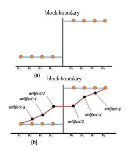
IV. Experiment Simulation and Result Analysis
V. Conclusion
References An Efficient Deblocking Filter Algorithm for Reduction of Blocking Artifacts in HEVC Standard
- D. Flynn, M. Naccari, K. Sharman, C. Rosewarne, J. Sole, G. J. Sullivan, T. Suzuki, "High Efficiency Video Coding (HEVC) Range Extensions text specification," 2014.
- K. McCann, B. Bross, W. Han, I. Kim, K. Sugimoto and G. Sullivan, "High efficiency video coding (HEVC) test model 12 (HM 12) encoder description," JCT-VC, Doc. JCTVC N, vol. 1002, 2013.
- Alan W.-C. Liew, Member, IEEE, Hong Yan, "Blocking Artifacts Suppression in Block-Coded Images Using Overcomplete Wavelet Representation," in IEEE TRANSACTIONS ON CIRCUITS AND SYSTEMS FOR VIDEO TECHNOLOGY, 2004.
- T. Wiegand, G. J. Sullivan, G. Bjّntegaard, A. Luthra, "Overview of the H.264/AVC Video Coding Standard," in IEEE Trans. on Circuits and Systems for Video Technology, 2003.
- F. Bossen, B. Bross, IEEE, K. S¨uhring, D. Flynn, "HEVC Complexity and Implementation Analysis," in IEEE Transactions on circuit and systems for video technology, 2012.
- Peter List, Anthony Joch, Jani Lainema, Gisle Bjّntegaard,Marta Karczewicz, "Adaptive Deblocking Filter," in IEEE Transactions on Circuits and Systems for Video Technology, 2003.
- G. J. Sullivan, J.-R. Ohm, W.-J. Han and T. Wiegand, "Overview of the high efficiency video coding (HEVC) standard," Circuits and Systems for Video Technology, IEEE Transactions on, vol. 22, no. 12, 2012.
- Hao Chen, Ruimin Hu,Yuan Gao, "An Effective Method of Deblocking Filter for H. 264/Avc," in Communications and Information Technologies, 2007. ISCIT'07. International Symposium on, 2007.
- Y. Luo, R.K Ward, "Removing the Blocking Artifacts of block based dct compressed images," in IEEE Trans. on Image process, 2003.
- Kang Runlong, Zhou Wei, Huang Xiaodong,Dong BingChao, "An efficient deblocking filter algorithm for HEVC," in Signal and Information Processing (ChinaSIP), 2014 IEEE China Summit & International Conference on, 2014.
- V. Srivastava, "A DCT based Algorithm for Artifacts Reduction from DCT coded Images," in Electronic Letters on Computer Vision and Image Analysis , 2009.
- Sonia Malik, Rekha Saroha, and Rohit Anand, "A SIMPLE ALGORITHM FOR REDUCTION OF BLOCKING ARTIFACTS USING SAWS TECHNIQUE BASED ON FUZZY LOGIC," International Journal Of Computational Engineering Research, pp. 1097-1101, 2012.
- Ramakrishna Palaparthi ,Vinay Kumar Srivastava, "A Simple Deblocking Method for Reduction of Blocking Artifacts," in Electrical, Electronics and Computer Science (SCEECS), 2012 IEEE Students' Conference on, 2012.
- Yuan Li, Ning Han, Chen Chen, "A Novel Deblocking Filter Algorithm In H.264 for Real Time Implementation," in Third International Conference on Multimedia and Ubiquitous Engineering, 2009.
- AF .Eldeken, AF; GI.Salama, "An Adaptive Deblocking Filter to Improve the Quality of the HEVC Standard," I.J. Image, Graphics and Signal Processing, vol. 7, pp. 9-15, February 2015.
- Y. Yuan, I.-K. Kim, X. Zheng, LingzhiLiu, X. Cao, S. Lee, M.-S. Cheon, T. Lee, Y. He and J.-H. Park, "Quadtree Based Nonsquare Block Structure for Inter Frame Coding in High Efficiency Video Coding," in Circuits and Systems for Video Technology, IEEE Transactions on, 2012.
- J.Vieron, "high efficiency video coding next generation video compression," in first research concerning 4K TV and HEVC codec, florida, 2013.
- Andrey Norkin, Gisle Bjøntegaard, Arild Fuldseth, Matthias Narroschke, Masaru Ikeda,, "HEVC Deblocking Filter," IEEE TRANSACTIONS ON CIRCUITS AND SYSTEMS FOR VIDEO TECHNOLOGY, vol. 22, 2012.
- B.Bross, W.Han, G.Sullivan, J.Ohm,T.Wiegand, "High efficiency video coding (HEVC) text specification draft 10 (JCTVCL1003)," in JCT-VC Meeting (Joint Collaborative Team of ISO/IEC MPEG & ITU-T VCEG), 2013.
- K. McCann, C. Rosewarne, B. Bross, M. Naccari, K. Sharman and G. Sullivan, "High Efficiency Video Coding (HEVC) Test Model 16 (HM 16) Encoder Description," 2014.
