An Energy-Aware Data-Gathering Protocol Based on Clustering using AUV in Underwater Sensor Networks

Author: Reza MotahariNasab, Ali Bohlooli, Neda Moghim
Journal: International Journal of Computer Network and Information Security(IJCNIS) @ijcnis
Article in issue: 12 vol.8, 2016.
Free access
Underwater Wireless Sensor Networks (UWSNs) consist of certain number of sensors and vehicles interacting with each other to collect data. In recent years, the use of Autonomous Underwater Vehicle (AUV) has improved the data delivery ratio and maximized the energy efficiency in UWSNs. Clustering is one of the effective techniques in energy management which increases the lifetime of these networks. One of the most important parameters in creating optimized clusters is the choice of appropriate cluster head (CH), which not only increases the lifetime of the network and the received data in the sink, but also reduces energy consumption. Clustering of networks was primary done via distributed methods in previous researches. It spends too much energy and also involves too many nodes in the clustering process and fades their main functionality, which is gathering data in sensor networks. It also causes more damping of the network. However, in the proposed protocol, instead of having them distributed by the network and the nodes, the stages of clustering and selecting the appropriate CH is the task of the AUV (Autonomous Underwater Vehicle). Since all the necessary measures to cluster in the network will be carried out by the AUV by this method, many control overheads in the process of clustering the network will be removed and energy consumption caused by nodes reduces significantly. With this method, the network scalability will also be manageable and under control. For simulating and implementing our method we mainly used the OPNET software. The results show that energy consumption of nodes in the proposed algorithm has been significantly improved compared to previous results.
Energy Optimization, Data Gathering, Underwater Sensor Networks, Autonomous Underwater Vehicle (AUV), Clustering
Short address: https://sciup.org/15011731
IDR: 15011731
Text of the scientific article An Energy-Aware Data-Gathering Protocol Based on Clustering using AUV in Underwater Sensor Networks
Published Online December 2016 in MECS
There has been a recent trend in deployment of underwater sensor networks (UWSNs) in various applications related to environmental and surveillance data acquisition in oceanic fields. Instead of radio and optical signals, most of the underwater communication systems use acoustic signals. However, the use of acoustic signals imposes many design challenges on communication protocol for UWSNs due to the high bit error rate, narrow bandwidth and long propagation delay.
Naturally, sensor nodes are forced to communicate with each other over a short distance (a possible way).
Various methods have been proposed for data gathering in these networks, and specific parameters of them have been improved which leads to the design and development of the autonomous underwater vehicle (AUV). AUV will facilitate network deployment, maximize network coverage, and enable high-speed networking.
In general, data gathering method can be divided into two categories based on the path a mobile sink travels: path-constrained and path-controlled.
By using the path-constrained scheme, the path of the mobile data sink is predetermined, whereas it is dynamically optimized in the path-controlled mode to conserve energy and improve data delivery rate.
In this paper, we design a communication protocol for application of an AUV gathering data from an underwater sensor network. Recent advances in the onboard processing capabilities of AUVs, permits us to perform increasingly sophisticated data collection tasks currently[1]. In particular, these advances make the in situ adaptation of AUV data-collection survey routes possible. This capability has the potential to ensure that the data collected at sea by an AUV meets the standards necessary for various subsequent objectives.
The remainder of this paper is organized as follows: Section II describes and examines the related works. Section III propose the network model. Section IV proposes our protocol for data gathering and energy consumption model used in underwater sensor networks. Section V validates our protocol through simulated deployments. Finally section VI presents our conclusions.
-
II. Related Work
Domingo and Prior [2], [3], [4] proposed a clustering approach where data is forwarded to a destination node in a single hop manner. Although this data forwarding technique is effective way to minimize the energy consumption in case of a large set of nodes, the issue of uniform consumption of energy still remains unsolved for cluster-heads. This arises the need for using a mobile node to collect data from neighbors in an UWSN. In addition, the issue of switching cluster heads is also very important that the leader should be considered.
It is shown that an AUV acting as a mobile sink can effectively reduce the transmission range of sensors[5], which leads to energy saving of transmission. In this way, an AUV travels a specified path and stops at location called "tour-point" for data gathering.
Same as the previous method [6], AUV is used to collect data UWSN networks. In such approaches, the probabilistic nature of the neighborhood, where successful communication probability is low, may result in retransmissions over the acoustic link. Beside AUV operational cost, these retransmissions add additional cost in term of excessive resource consumption.
Authors have analyzed the usage of a special fixed node to gather data from static acoustic sensor network[7, 8]. In this approach, fixed nodes collect data from neighbor nodes and forwards it to AUV during data gathering tour. However, the authors have not discussed the issue of non-uniform energy consumption during AUV data gathering and the rapid depletion of energy at the fixed node. This could be one of the important drawbacks of this approach.
Clustering is another important issue that should be considered in underwater networks. One of the most famous hierarchical routing protocols based on clustering, is the LEACH protocol. In this method, each cluster member send their data to cluster head. The cluster head aggregate this data and send it to the BS, thus the cost of communication will reduce dramatically.
Many improvements have been made in LEACH protocol so far. LEACH-C method is an example of these improvements. In LEACH-C, the forming of clusters is done using a centralized algorithm by base station in starting of each period. Base Station uses the received information from nodes for finding the predetermined number of cluster heads and network configuration within the clusters.
Some algorithms that based on not sending the correlated data are considered. The TINA algorithm is one of them. In this algorithm the sensor node compares the value of sampled data with previous data, if it found them having different values, it will send them; otherwise it goes to sleep mode. The proposed improvement to this algorithm could be that sensor node decides to send data after comparing the value of new sample with last reported data.
Maximum Amount Shortest Path (MASP) scheme is proposed to increase the network throughput with better energy efficiency by optimizing the assignment of sensor nodes[9]. Genetic algorithm (GA) is utilized jointly with the integer linear programming to derive the mobile sink’s path. Authors have presented a data collection scheme that is optimized by considering multi-hop routing[10].
The authors [11] extended the concept of the Traveling Salesperson Problem (TSP) and proposed an algorithm for AUV path planning so as to maximize the amount of collected information and minimize the travel time.
-
III. Network Model
The proposed network architecture is made up from sensor nodes that are fixed on the ocean floor. Sensor nodes are organized into clusters and a cluster has a cluster head node. In order to choose a cluster head node, a special algorithm is applied, wherein various criteria are considered, including the remaining energy and the distance to the path of the AUV. Fig.1. shows this architecture.
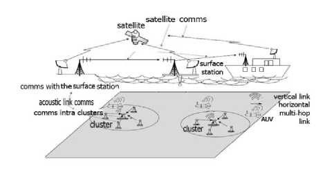
Fig.1. Static Two-Dimensional Underwater Acoustic Networks [12]
In this method, the cluster head nodes collect data from the sensor nodes and delivers it to the mobile sink (AUV).
Clustering with the help of AUV is done via this method, where after placing all the sensor nodes on the ocean bed and fixing them, the AUV enters the area of the sensor network and after each t seconds it makes a signal with an R acoustic range. This acoustic signal expands in the underwater space in the form of threedimensional shape and active nodes that are in the acoustic range of the signal. In other words, the nodes that this released signal covers by AUV will receive this signal. The content of the Hello packet which is sent by the AUV includes the id, which is the same number of the determined clusters by the AUV. Each node that receives this packet saves the number of clusters and thus becomes a member of this cluster. After every t seconds, the AUV moves forward and the value of one id unit increases. Finally the identified clusters with different id will be formed. Fig.2. shows how a cluster with the above stated method is created.
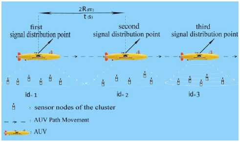
Fig.2. Clustering Network using AUV
The time span, after which the AUV sends the Hello packet, is obtained from Equation 1:
гр _2R v
Where, 2R is the maximum communication range of two distanced nodes and v is the speed of the AUV. Fig.3. shows clustering flowchart from the perspective of AUV.
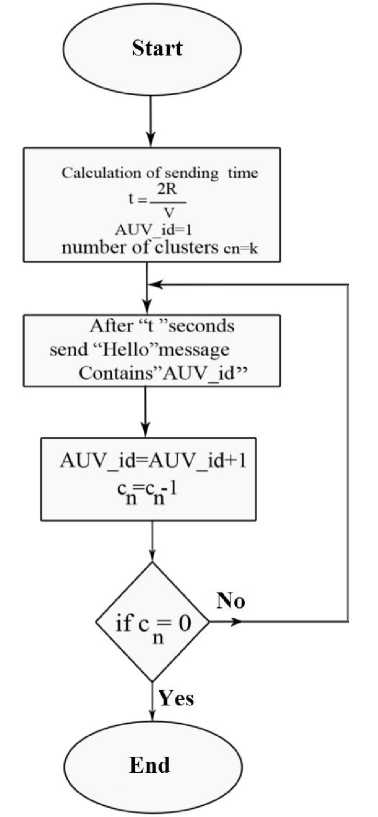
Fig.3. Clustering flowchart from the Perspective of AUV
Using this method for clustering the nodes has several advantages; for example it improves the energy consumption of the system. The other advantage of this method is the ability to adjust and control the size of the cluster and the number of nodes in the cluster. By changing the power of the sent signal from the AUV side, the range of the released signal is changed and therefore the number of nodes in the cluster can also change to lees and more. Improving the scalability is also one of the other important advantages of using this method in clustering the network. Also, due to the low volume of the package sent from AUV, which only includes one id, the use of this method therefore will have no overhead in transportation and in calculations. For this reason, the amount of memory used by the nodes will also decrease.
-
IV. The Proposed Protocol for Data Gathering
After the formation of clusters in question, data gathering from the network will be conducted in three phases:
-
1) First Phase : The phase of selecting the cluster head nodes
-
2) Second phase : Data gathering phase, where the data is sent to the cluster head node by nodes.
-
3) Third phase : Transition phase, where the collected data by the cluster head node is sent to the AUV.
-
A. The Method of Selecting the Cluster Head Node
Energy parameters and the geographical locations are among the most important parameters that affect the determining of the cluster head node. In the proposed method of this paper, a node is chosen as a cluster head node. Beside having the initial conditions (needed energy), it also has the shortest distance to moving path of the AUV. Therefore, for each i node, the Wi weight is considered for underwater sensor network. Equation 2 describes how to calculate the Wi weight.
Wi = (2)
In this equation, Ci is the remaining energy level of the i node and Di shows the distance of i node from the AUV path.
-
B. The Steps of the Proposed Algorithm
In order to select the cluster head node, a timer is assigned for each node. The stages of selecting the cluster head node by the help of the node weight ( W i ) and the included timer is as follows:
First step: In order to use the timer in the nodes, we firstly need to synchronize the nodes with each other in such a way that with releasing a strong signal, the AUV synchronizes the nodes in the network. When the nodes receive the setup signal from the AUV, they proceed to set their timer, the value of which is (ti) and is set corresponding to the node weight (Wi). It should be noted that the amount of ti should have an inverse relation with the node weight (Wi).
Second step : The first node that its timer reached zero will be known as the cluster head node and will send a special data packet called CH-ADV to all nodes. This packet includes the node number, the cluster number that the AUV has sent to it in the development phase of the cluster and the amount of CH-Count, which indicates the number of times that this node is selected as a cluster head node. The nodes that receive this packet specify whether or not the number of the cluster in the message is equal to the number of the cluster they had saved themselves. If there is a match, the node in question accepts the data packet sent from the cluster head node and stops its timer then saves the number of that node as the number of the cluster head node. Otherwise, it will destroy the received packet and continue to decrease its timer until it receives a new packet from an appropriate cluster head node or its timer hits zero.
Third step : After all nodes of a cluster receive the CH-ADV message of the cluster head node, they send their weight ( W i ) and their other data in a Data message to the cluster head node. The cluster head node stores these values in its memory so they can be delivered to the AUV later.
Fourth step : When a cluster head node receives the Data message from a sensor node, it waits for a certain time (about 70 ms), then proceeds to send the END message to the entire cluster. This message will indicate the end of the data gathering phase and the starting of the transition phase. In order to save energy as in the period one, each node goes to sleep mode upon receiving the END message.
Fifth step : As the transition phase begins, the cluster head node will wait to be located in the communication range of the AUV. Upon arrival of the AUV to the considered area and after it sends the message of Data – Req, the cluster head node starts communicating with AUV and sends the stored data to it. Other nodes also start to calculate their own weight by getting the message ( Wi ) and then adjust their amount based on Wi .
Sixth step : At this stage, besides receiving the sent data from the cluster head node, the AUV also compares the node weight with the threshold weight ( W th ). If the cluster head node weight ( W ch ) is smaller than the threshold weight, the Setup message is sent to all nodes by AUV (back to the first stage) and then the process of the selecting of the head node will be resumed. If the cluster head node weight is not less than the threshold weight, the AUV does not send a message to the nodes and so they are allowed to continue to work, which is sending the collected data to the cluster head node.
-
C. Model of Energy Consumption Used In Underwater Sensor Networks
Sensor networks lifetime depends on the energy consumption of the nodes in that network. In order to estimate the energy consumed by each type of sensors in the underwater networks, the acoustic signal propagation model, proposed by Yorick [13], is used. Equation 3 [14] shows the ratio of the signal to noise in the underwater propagated signal in the receiver:
SNR = - TL - NL - DI (3)
In this equation, SL is the noise of the source level, TL represents weakness, NL represents the source noise level and DI represents the direction of propagation. All the values in the formula are based on dB.
Factors that are influential in obtaining the NL in underwater sensor networks include: disturbance
(perturbation) ( Nt ), shipping (transport) ( Ns ), noise from rotating impeller ( Nw ) and thermal noises ( Nth ) based on the influencing parameters on the noise, the overall noise of NL is calculated by Equation 4:
N ( f )= Nt ( f ) + Ns ( f ) + Nw ( f ) + Nt ℎ( f ) (4)
The DI value for the network is considered to be zero, because it is assumed that the direction of propagation and the receiving of the underwater acoustic signals are from all the directions.
The weakening ( TL ) related to the parameters of absorption and spread is obtained by Equation 5[15]:
TL = ×10 log d + d .10 log a ( f ) (5)
Where in equation 5 the first part is related to the parameter of spread and the second part is related to the parameter of absorption. K factor indicates the type of signal expansion. Therefore, k = 1 represents cylinder release, k = 2 represents spherical release, and k = 1. 5 shows it is in practical and useful status. d also represents expansion distance of the signal in meters.
Thorpe Equation [14,15] also calculates the absorption rate:
a ( f )= (0.11 + 44 + 2.74 ×
W У V 1+f2 4100+f2
10"4/2 + 0.003). 10"3 f ≥0/4
And
« ( f ) =
(0.002 + 0.11 1+f2 +0.011 P ). 10~3 f ≤0.4
We assume the amount of noise in receiver is15dB. To calculate the amount of SL in Formula 3, the transferred signal intensity (It) should be calculated.
It = 10 SL ⁄ 10 × 0.67 × 10 18watt / m2 (8)
Therefore, the energy transfer based on every bit can be calculated as follows:
Pb = 2 × 3.14 × ℎ × It (9)
Where h is the depth of network in the ocean in meters.
With the help of the above equations, one can calculate the consumed energy for each transmission of the END and CH-ADV messages.
Equation 10 is used to calculate the consumed energy of the sensor nodes:
E _ nc ℎ = E _ setup _ nc ℎ+ E _ data _ nc ℎ = ( CH _ ADV _ R + Data. _ T + Ack _ R + END _ R
+ Ack _ T ) (10)
And the consumed energy by the cluster head node is also calculated by Equation 11:
E _ c ℎ = E _ setup _ c ℎ + E _ data _ c ℎ
+ E _ forward. _ c ℎ
= ( CH _ ADV _ T + Data _ R × N + END _ T +
Data _ total _ T + Ack _ R )
In equations 9 and 11, nch refers to sensor nodes, ch refers to head node, T refers to transmission, R means receiving and f represents transmission frequency. Equations 3 to 11 are used for estimating the network lifetime based on the consumed energy of different nodes as well as the cluster’s various operations such as the formation of cluster, data gathering, and data transmission to the AUV [16].
-
V. Evaluating the Performance of The Proposed Protocol
The results presented in this section are the outcomes of simulation in OPNET simulator, which are implemented based on the parameters in Table 1. The results for the different seeds are repeated several times, and the results in each test are recorded and the final result is obtained via averaging the results of the carried out tests. In our simulation model, we consider packet error rate of 10-3 for binary shift keying (BPSK) modulation. In addition, we assume the nominal speed of sound as 1500 m/s in acoustic channel to simulate propagation delay. The detail of the acoustic link parameters used in our simulation model is given in Table 1.
It should be noted that each of the nodes in the network and the mobile node (AUV) is equipped with acoustic modes WHOI (Micro-Modem) for making acoustic voice communication [17], [18]. For this reason, the modem features should be considered in the simulation.
Fig.4. shows the process model related to the AUV and Fig.5. shows the process model of the sensor node in OPNET simulator.
As shown in Fig.4. and Fig.5., these process models are composed of multiple functions, each of which are responsible for specific tasks and as soon as the necessary conditions are established, they are performed. Among the functions included in these process models there can be the production of desired packets, functions of receiving the incoming packets, the transfer function of the normal node to the cluster head node and vice versa, the function of introducing the cluster head node, etc.
It should be noted that the conditions of transition from one state to another, demand the establishing of the necessary conditions that these conditions should be defined in the simulator.
Table 1. The Initial Conditions And acoustic Link Parameters used In the Simulation
|
Parameters |
Values |
|
Channel Bandwidth |
4KHz |
|
Central Frequency |
25 KHz |
|
Data Packet Length |
1024bits |
|
Control Packet Length |
32bits |
|
Data Rate |
2500bps |
|
Power |
50w |
|
AUV Speed |
2m/s |
|
Number Of Clusters |
8 |
|
Number Of Nodes In Each Cluster |
6 |
|
Total Number Of Nodes |
48 |
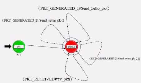
Fig.4. Process Model of the AUV
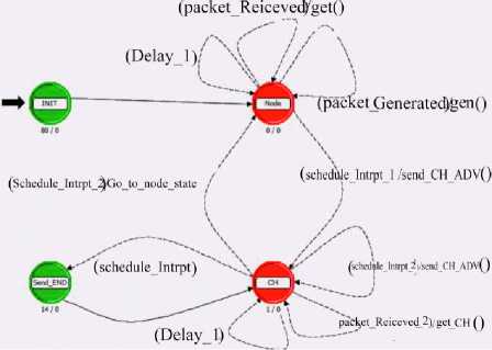
Fig.5. Process Model of the Sensor Node
The battery power of the underwater acoustic wireless sensor network node is limited. So, when the energy runs out, the node will fail, resulting in the network partitioning or even crashing the entire network. Therefore, how to reduce energy consumption and prolong network life cycle are key issues the study of underwater acoustic wireless sensor network. Fig.6. shows the maximum energy consumption by nodes and Fig.7. shows the minimum energy consumption based on simulation time. This time is roughly equal to 3600 Seconds.
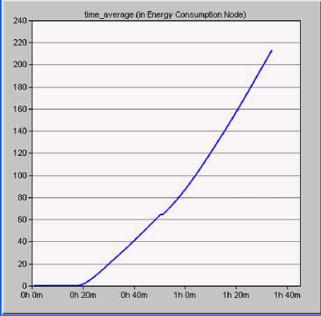
Fig.6. Maximum Energy Consumption by the Node
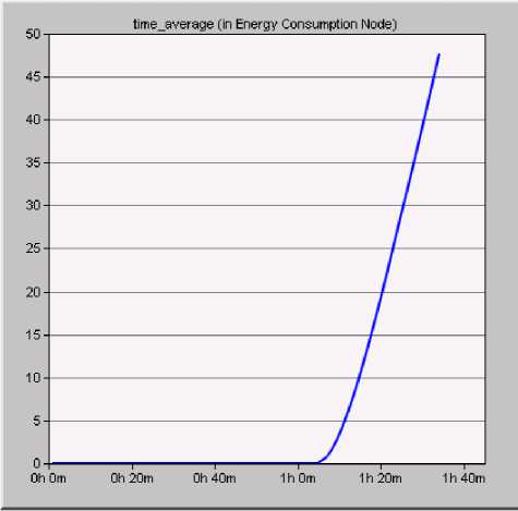
Fig.7. Minimum Energy Consumption by the Node
The maximum power consumption (Fig.6.) is related to the cluster head node (CH) and the minimum energy consumption (Fig.7.) is related to the typical sensor node. As shown in the Figures, since it has more message exchanges compared to other nodes, the CH consumes more energy than other nodes. Nevertheless, according to Fig.6. and Fig.7., as long as each node has no message exchanges with other nodes or the AUV, its energy consumption is almost zero and after establishing the necessary and desired data exchange (between nodes and CH or between CH and AUV) the energy consumptions would have an increasing process. In this proposed scheme, the energy is saved at each phase of the clustering scheme. For example, only AUV is allowed to work during the initial phase. Also, data aggregation with similarity function can save energy by reducing the number of transmissions from cluster heads to the AUV.
Fig.8. compares the ratio of the signal to the noise in the AUV and the node. As it is clear, by the increase in simulation time, the ratio of signal to the noise is decreased up to approximately 40dB.
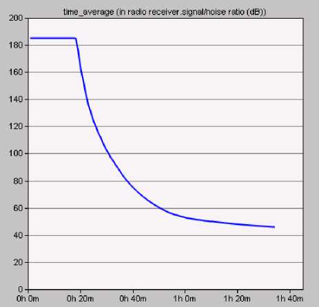
Fig.8. Signal to the Noise Ratio (SNR)
In Fig.9., the results are compared with the BGAF algorithm [18], which is a clustering algorithm in the underwater networks. Comparison of the charts shows that the proposed algorithm has a better function than the BGAF algorithm.
Experiments as well as show that the proposed algorithm is very reasonable for the mechanisms to balancing network load and extending the network life cycle.
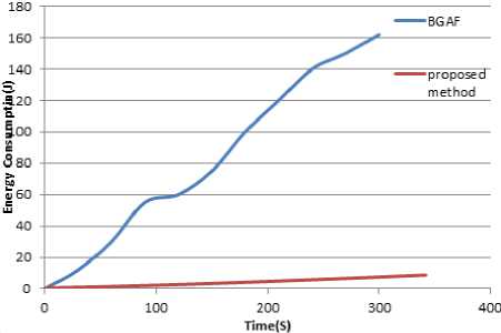
Fig.9. Comparing the Energy Consumption of the Proposed Protocol with BGAF Algorithm
-
VI. Conclusion
Various techniques are known for collecting data from acoustic underwater networks, each of them has their own advantages and disadvantages. In this paper we proposed a method for decreasing energy consumption in sensor networks; given that the energy consumption is a subject undergoing intense study with broad and current interests. We continue our work through selecting the most appropriate method, which is the clustering of nodes and determining a cluster head node for it. Beside decreasing the consumed energy of the nodes, this method will also create flexibility in the network and will increases its lifetime. The OPNET simulator is used for implementing this algorithm in our simulation environment. The results of this simulation indicate that the proposed algorithm was quite successful in its task. We foresee this method could be used in collecting data from the sensor nodes by the AUV robots in future.
References An Energy-Aware Data-Gathering Protocol Based on Clustering using AUV in Underwater Sensor Networks
- Z. Latifi, K. Jamshidi and A. Bohlooli, "Increasing the Efficiency of IDS Systems by Hardware Implementation of Packet Capturing", in I. J. Computer Network and Information Security (IJCNIS), Vol. 10, pp. 30-36, 2013.
- M. C. Domingo, R. Prior, "Energy analysis of routing protocol for underwater wireless sensor networks," Elesvier. Computer Communications, 31, 2008.
- M. C. Domingo, R. Prior, "A distributed clustering scheme for underwater wireless sensor network, " In Proc. IEEE PPIMRC, Athens, September, 2007.
- H. Harb, A. Makhoul, and R. Couturier, " An Enhanced K-means and ANOVA-based Clustering Approach for Similarity Aggregation in Underwater Wireless Sensor Networks", in IEEE Sensors Journal, MARCH 2015.
- G. A. Hollinger, S. Choudhary, P. Qarabaqi, C. Murphy, U. Mithra, G. S. Sukhatme, M. Stojanovic, H. Singh, and F. Hover, "Underwater Data Collection Using Robotic Sensor Networks, "In IEEE. Journal on Selected Area in Communications, Vol. 30, No. 5, June, 2011.
- F. Favaro, P. Casari, F. Guerra and M. Zrozi, "Data upload from a static underwater network to an AUV: Polling or random access?, " In Proc. MTS / IEEE Oceans Yeosu, Korea, May, 2012.
- F. Favaro, L. Brolo, G. Toso, P. Casari and M. Zrozi, " A Study on Remote Data Retrieval Strategies in Underwater Acoustic Network, " In Proc. MTS IEEE Oceans San Diego, US, September 2013.
- N. Ilyasa, T. A. Alghamdib, M. N. Farooqa, B. Mehbooba, A. H. Sadiqa, U. Qasimc, Z. A. Khand, N. Javaid, " AEDG: AUV-aided Efficient Data Gathering Routing Protocol for Underwater Wireless Sensor Networks", in Elesvier Procedia Computer Science, 2015.
- S. Gao, H. Zhang, and S. Das, "Efficient data collection in wireless sensor networks with path-constrained mobile sinks," IEEE Trans. Mobile Comput. , vol. 10, no. 4, pp. 592–608, Apr. 2011.
- J. L. and J. P. Hubaux, "Joint mobility and routing for lifetime elongation in wireless sensor networks," in Proc. IEEE INFOCOM, vol. 3, Mar. 2005.
- G. A. Hollinger, U. Mitra, G. S. Sukhatme, " Autonomous data collection from underwater sensor networks using acoustic communication", In Intelligent Robots and Systems (IROS), IEEE/RSJ International Conference on, pp. 3564-3570, 2012.
- D. Jabba And M. Labrador, "A Data Link Layer In Support of Swarming of Autonomous Underwater Vehicles," In Proceedings Of The MTS/IEEE Oceans Conference, Bremen, Germany, May 2009.
- M. Stojanovic. "Acoustic (Underwater) Communications". In John G. Proakis, editor, Encyclopedia of Telecommunications. John Wiley and Sons, 2003.
- C. Pelekanakis, M. Stojanovic, and L. Freitag. "High rate acoustic link for underwater video transmission". InProc. of MTS/IEEE OCEANS 2003, vol.2, pp. 1091–1097, San Diego, CA, USA, September.
- T. Melodia, H. Kulhandjian, L. C. Kuo, E. Demirors, " Advances In Underwater Acoustic Networking", in Wiley Online Library, May 2013.
- Z. Heidarian, N. Movahedinia, N. Moghim, P. Mahdinia, "Intrusion Detection Based on Normal Traffic Specifications", in I. J. Computer Network and Information Security (IJCNIS), Vol. 9, pp. 32-38, 2015.
- D. Richard Blidberg, "The Development of Autonomous Underwater Vehicles (AUV); A Brief Summary", Autonomous Undersea Systems Institute, Lee New Hampshire, USA, 2010.
- S. Sendra, J. Lloret, J. M. Jimenez, and L. Parra, "Underwater Acoustic Modems", in IEEE Sensors Journal, Vol. 16, No. 11, June 1, 2016.
- G. Liu, W. Wen, "A improved GAF clustering algorithm for three-dimensional underwater acoustic networks", in IEEE International Symposium on Computer, Communication, Control and Automation, 2010.
