An extended approach for enhancing packet-loss of inter-SGSN in 3G mobile networks

Author: Shadi Nashwan, Ala Hamarsheh
Journal: International Journal of Computer Network and Information Security @ijcnis
Article in issue: 11 vol.9, 2017.
Free access
This paper presents a new SRNC relocation approach based on BOFC functions. The new approach handles all possible combinations of the user equipment movements, particularly, when it moves across overlapped regions with different GGSN branches. Additionally, it integrates both RNC and BS levels in order to reduce the number of packets loss during the hard handover process. The experimental results showed that the new approach reduces the packet-loss ratio in comparison to both SRNC and BOFC approaches. Besides, the experimental results showed that the average execution time of the handover procedure in each network component is closed to the average execution time of the BOFC approach.
3G, 3GPP, Mobility Management, HSDPA, BOFC
Short address: https://sciup.org/15015553
IDR: 15015553 | DOI: 10.5815/ijcnis.2017.11.05
Text of the scientific article An extended approach for enhancing packet-loss of inter-SGSN in 3G mobile networks
Published Online November 2017 in MECS DOI: 10.5815/ijcnis.2017.11.05
Mobile devices play a vital role in providing the leading-edge to internet services. In order to enhance the quality of voice and multimedia services with higher data rate in third generation (3G) networks, the Third Generation Partnership Project (3GPP) was developed the Universal Mobile Telecommunication System (UMTS) [1].
The UMTS architecture components can be summarized as the following [2][3][4]: (1) the Gateway GPRS Support Node (GGSN) provides the connection with the external Packet Data Network (PDN) networks and IP Multimedia Core Network Subsystem (IMS), in the same time the is connected with one or more Serving GPRS Support Node (SGSN) by the Gn interfaces; (2) the SGSN handles all packet frames within the network, both SGSN and GGSS have to be connected to the Home Subscriber Server (HSS) to obtain the all mobility management information for all user equipment’s (UE’s); (3) the latter communicates with core network through the UMTS Terrestrial Radio Access Network (UTRAN). Moreover, it includes a set of radio network controllers
(RNC’s) and Base stations (BS’s); (4) the RNC is connected with the one SGSN and a set of BS’s; (5) the latter communicates with a set of UE’s. The UE communicates with one or more BS’s by the UE using based on the Wideband CDMA (WCDMA) technology [4]. Figure 1 shows UMTS network components.
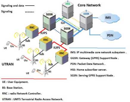
Fig.1. The Architecture of a 3G Network
In the UMTS network, packets are routed between the UE and the GGSN based on the CDMA technology. Therefore, more than one path could be established to deliver the same packets to the UE through more than one BS. Additionally, more than one RNC that are belonging to the same SGSN or two different SGSN’s. The UMTS Mobility Management (UMM) procedures are responsible for supporting these services to the subscribers.
The main problems associated with the UMM can be classified as follows: (1) the packet frames loss problem during the reallocation process either on the BS level or RNC level; (2) the buffer overflow of the non-serving BS and RNC components. Particularly, both problems can be occurred during either Intra-SGSN or inter-SGSN reallocation process [5]. It is plausible to suggest that the majority solutions to solve UMM problems in the reported investigative works are formulated either on the
BS’s level or RNC’s level.
Several approaches have been proposed to recover packet frames loss problem during the RNC’s reallocation as result to the inter-SGSN reallocation [5][6] [7][9]. These approaches are based on either path duplication during RNC reallocation process or using packet frames buffering mechanism to avoid the packet loss at the target RNC without taking into account the loos of packet frames in the base stations level. Lin et al. [7] propose the basic overflow control schemes (BOFC) based on a new packet frames buffering mechanism to avoid packet loss during only the intra-SGSN reallocation process. These approaches resolve problems in an individual basis. They did not take into account the overlapping between multiple levels of network components. Knowing that these levels lead to packet frames loss. The authors believe that reducing and enhancing the packet loss ratio during handover procedure is an important and interesting research topic especially in sensitive and restricted space environment, like UMTS network, where mobile devices are considered as one of the poorest resource platform.
This research aims to extend the BOFC scheme functions to enhance the packet frames loss ratio for the reallocation of serving radio network controller (SRNC) process during either the Intra-SGSN or inter-SGSN handover. This can be achieved by decreasing the ratio of packet-loss whether at source RNC (SRNC) or at target RNC (TRNC) when the UE moves from base station to another within overlap SGSN regions. The new scheme is based on extended the BOFC scheme functions that are treated on the RNCs and BS levels [7].
This paper is organized as follows. Section 2 illustrates the BOFC scheme functions. The proposed scheme functions are introduced in section 3. Results and Discussions of the proposed approach are illustrated in section 4. Finally, section 5 concludes the paper.
-
II. Related Works
In this section, we first introduce the active set concept and the notation of BOFC scheme, respectively. Then the BOFC scheme functions description are discussed [7][10].
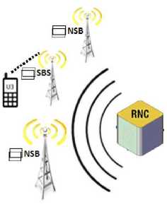
Fig.2. The UE Connects with the Active Set
-
A. Active set of BS
The 3GPP proposed the High-Speed downlink packet access (HSDPA) approach [11], [12]. In the HSDPA approach, the UE connects to three BSs that are belong to one active set [8]. The UE chooses only one BS as serving BS (SBS) in the active set. The serving RNC (SRNC) forwards the packet frames to the all BS’s in the active set. The SBS forwards the packet frames to the UE. The other non-serving BS’s (NBSs) in the active set store the packet frames in their buffers as shown in figure 2. If the link quality between the SBS and UE deceases below a threshold value (i.e. determined by the network operator), then the active set will be reestablished, the UE chooses another better BS in the active set as a new SBS and one of the NSB may go out from the active set. Consequently, the next packet frames will be forwarded from new SBS to the UE.
-
B. BOFC Scheme Notation
Table 1. BOFC Scheme Notation
|
CRUE |
Number of packet frames that are received by UE from SBS. |
|
CRRNC |
Number of packets frame that are sent to UE from SRNC. |
|
CRS |
Number of packet frames that are received by SBS from SRNC. |
|
CRI |
Number of packets frame that are received by NBS from SRNC. |
|
CSI |
Number of packets frame that are deleted from the buffer of NBS. |
|
CSS |
Number of packets frame that are sent to UE from SBS. |
|
NI |
Buffer size of NBS. |
|
NS |
Buffer size of SBS. |
|
W |
Window size. |
|
KI |
Number of packets currently that are stored in the buffer of NBS. |
|
KS |
Number of packets currently that are stored in the buffer of SBS. |
|
FS |
Flag to indicate the buffer whether is overflow or not. |
|
WIS |
Indicate to the number of packets frame received in the current window. |
|
NSYN |
Synchronization parameter. |
|
ACK |
Acknowledgment. |
|
NAKA |
Non acknowledgment. |
-
C. BOFC Functions Description
The NBSs’ buffers might be overflowed if the NBSs did not send packet frames to the UE. Many approaches were proposed to solve the buffer overflow problem. These approaches assure that any previously received packet frames will be dropped safely if the buffer of NBSs is full. After that, no packet frames will be lost after a UE has switched the link to a new SBS [13].
The packet frames buffering mechanism of the BOFC scheme can be divided into five function as follows: (1) overflow control function which is executed by the SRNC; (2) overflow control function which is executed by the SBS ;(3) overflow control function which is executed by the UE; (4) overflow control function which is executed in NBS; (5) the buffer frames synchronization function which is performed by the new SBS.
The UE recognizes a counter (CRUE) to indicate the number of received packet frames. When the UE changes the wireless link after active set reallocation, then the CRUE value will be sent to the new serving cell for frame synchronization. Let the SBS and NBS both in active set and have the parameter identities (S) and (I) respectively. Then, every BS in the new active set recognizes a buffer of size (N) for each downlink transmission. Let (K) is the number of packet frames currently stored in buffer in BS in active set. Also the CR count the number of packet frames received from SRNC. The CS count the number of packet frames that have been processed by BS in active set. If the BS is SBS, then (CS = CSS) to show the number of packet frames that are received by UE. Additionally, if the BS is NBS, then (CS = CSI) shows the number of packet frames that are deleted from buffer of the NBS. A counter (CSRNC) is recognized by the SRNC to record the number of packet frames that have been received by the SBS. Table 1 shows all input and output parameters of the BOFC scheme functions.
-
D. Overflow Control Function of the SRNC (BOFC-SRNC)
// OVERFLOW CONTROL FUNCTION OF THE SRNC STEPS:
// LINE 0:CRRNC = 0, W IS PREDEFINED BY THE OPERATOR;
// LINE 1:BEGIN;
// LINE 2:WHILE CRRNC MOD W NOT EQUAL 0
// LINE 3:START;
// LINE 4:CRRNC++;
// LINE 5:STOP;
// LINE 6:WAIT UNTIL RECEIVED ACK FROM
SBS;
// LINE 7:GOTO LINE 1;
// LINE 8:END;
Fig.3. BOFC Function that is executed by the SRNC.
The Overflow control function of the SRNC (BOFC-SRNC) is a window-based flow control function as shown in figure 3. The SRNC executes the BOFC-SRNC function using window size (w) that is used for downlink transmission from the SRNC to the SBS. After a SRNC sent all packet-frames of the current window, it must wait until an acknowledgement (ACK) message is received from the SBS. After that, it will be ready to forward the packet frames of the next window. The SRNC sends a packet frame to every BS in the active set and increments the CRSRNC.
-
E. Overflow Control Functions of the SBS (BOFC-SBS)
// INITIALIZE THE GLOBAL VARIABLES OF THE SBS;
// LINE 0:CSS:=;
// LINE 1:KS:=0;
// LINE 2:WIS:=0;
// LINE 3:CRS:=0;
// LINE 3:FS:=0;
-
(a) Initialize the Global Variables of the SBS.
// OVERFLOW CONTROL FUNCTION BETWEEN THE SBS AND SRNC
// LINE 0:BEGIN;
// LINE 1:CRS++;
// LINE 2:WIS:= CRS MOD W;
// LINE 3:WHILE WIS NOT EQUAL 0;
// LINE 4:START;
// LINE 5:CRS++;
// LINE 6:WIS:= CRS MOD IS EQUAL W;
// LINE 7:STOP;
// LINE 8:KS:= CRS–CSS;
// LINE 9:INCASE KS IS LESS THAN OR EQUAL TO NS–W;
// LINE 10:BEGIN;
// LINE 11:TRANSMIT AKA TO SRNC;
// LINE 12:GOTO LINE 3;
// LINE 13:END;
// LINE 14:INCASE KS IS GREATER THAN NS– W;
// LINE 15 BEGIN;
// LINE 16:FS:=1;
// LINE 17:WAIT UNTIL TO BE SPACE IN BUFFER AND FS:=0;
// LINE 18:GOTO LINE 9;
// LINE 19:END;
// LINE 20:END;
-
(b) SRNC- SBS function.
// OVERFLOW CONTROL FUNCTION BETWEEN THE SBS AND UE
// LINE 0:RECEIVED THE AKA MESSAGE FROM UE;
// LINE 1:BEGIN;
// LINE 2:DELETE FROM FIRST RECEIVED
PACKET FRAMES FROM BUFFER;
// LINE 3:CSS++;
// LINE 4:KS:= CRS-CSS;
// LINE 5:END;
-
(c) UE-SBS function.
Fig.4. BOFC Functions that are executed by the SBS.
Figure 4. (a)-(c) show the overflow control function (BOFC-SBS) that is performed by SBS to flow control the packet frames with the SRNC and UE, respectively. In order to control the overflow with the SRNC, the SBS uses the FS that indicates if the buffer of the SBS is overflowed (i.e. if the value of (FS = 1)). The parameter WIS indicates the number of packet frames that is received by the SBS of the current window. The BOFC-SBS function consists of the following sections: (1) in the first section; the SBS counts the number of packet frames that are received from the SRNC as (CRS=CRS+1); sets the number of packet frames in the buffer to (KS:= CRS– CS), counts the number of received packet frames within a window as (WIS:= CRS mod w); (2) in the second section, the SBS calculates both values of WIS and KS to decide whether it can receive the next packet frames from the SRNC or not. In order to control the overflow with the UE, the SBS deletes the first received packet frames from buffer. Therefore, deletion process must be executed safely, the SBS the increments the CRS by 1 and the KS as (KS = CRS- CSS).
-
F. Overflow Control Function of the UE
|
// OVERFLOW CONTROL FUNCTION BEWEEN THE |
|
SBS AND UE |
|
// LINE 0:CRUE; |
|
// LINE 1:BEGIN; |
|
// LINE 2:SEND AKA TO SERVING SBS; |
|
// LINE 3:CRUE++; |
|
// LINE 4:END; |
Fig.5. BOFC Function that is executed by the UE.
Figure 5 shows the overflow control function (BOFC-UE) that is executed by the UE. In this function, the UE checks the packet frames that are received from the SBS whether is corrupted or not. If the UE receives a corrupted packet frame, then it returns a NACK message to SBS, then the SBS will resend the packet frames to the UE. In case the UE receives not corrupted packet frame from SBS, then the UE will increment the CRUR counter by 1, and returns an ACK message to the SBS.
// FRAME SYNCHRONIZATION FUNCTION OF A NEW SBS.
// LINE 0:NSYN, CS, CRI, CRUE;
// LINE 1:BEGIN;
// LINE 2:NSYN:= CRUE - CS;
// LINE 3:IN CASE NSYN IS LESS THAN OR
EQUAL K;
// LINE 4:DELETE FROM THE FIRST INDEXES
FROM THE BUFFER EQUAL TO NSYN;
// LINE 5:IN CASE NSYN IS GREATER THAN
K;
// LINE 6:START;
// LINE 7:DELETE FROM THE FIRST INDEXES
FROM THE BUFFER EQUAL TO K;
// LINE 8:DELETE FROM THE FIRST INDEXES
FROM THE BUFFER EQUAL TO NSYN – K;
// LINE 9:STOP;
// LINE 10:CS:= CS + NSYN;
// LINE 11:N:=N – W;
// LINE 12:END;
-
G. Overflow Control Function of the NBS (BOFC-NSB)
Fig.7. BOFC Function that is executed by a new SBS.
// OVERFLOW CONTROL FUNCTION BEWEEN THE NBS
// LINE 0:Ki, CRI, CSI;
// LINE 1:BEGIN;
// LINE 2:KI:= CRI – CSI;
// LINE 3:WHILE KI IS NOT EQUAL TO NI;
// LINE 4:START;
// LINE 5:CRI++;
// LINE 6:GOTO LINE 2;
// LINE 7:STOP;
// LINE 8:DELETE THE FIRST INDEX IN THE
BUFFER;
// LINE 9:CSI++;
// LINE 10:GOTO LINE 2;
// LINE 11:END;
Fig.6. BOFC Function that is executed by the NSB.
Figure 6 shows the overflow control function (BOFC-NSB) that is performed by the NBS. When the NBS receives a packet frames from the SRNC, the NBS sets the value of the Ki as (KI= CRI – CSI). In case the buffer is full where the KI is equal to the NI, the NBS deletes the first index in the buffer and increments CSI by 1. In case the KI is not equal to the NI, the NBS insert the received packet frames at the last index of the buffer and increments the value of the CRI by 1.
-
H. Buffer Frames Synchronization Function (BOFC-BFS)
Figure 7 shows Buffer frames synchronization function (BOFC-BFS) that is performed by a new SBS. Once of the NBSs after the active set reallocation process becomes the SBS. The new SBS performs the following steps: (1) determines the value of NSYN as (NSYN = CRUE – CS); (2) determines the value of K as (K = CRI – CS), where the CS is similar to previously determined CSI value; (3) in case NSYN ≤ K, then the new SBS deletes the NSYN packet frames from the first indexes of the new SBS buffer. If the value of the NSYN is greater than K, then the new SBS deletes K packet frames from the first indexes of the new SBS buffer and removes the next (NSYN – K) packet frames.
-
III. Extended BOFC Scheme (EBOFC)
In this part, an extended BOFC scheme based on the BOFC functions is proposed to enhance the packets loss ration during the Inter- SGSN reallocation process in 3G mobile networks (called EBOFC). Comparing with the BOFC scheme, the EBOFC scheme cannot enhance the loss ratio only in the Intra-SGSN reallocation process only, but also can reduce the number of packet frames loss in the Inter-SGSN reallocation process.
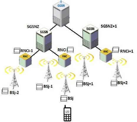
Fig.8. Intra-SGSN and Inter-SGSN Reallocation.
Figure 8 illustrates the reallocation cases. Suppose that, the active set now is equal to BSj-1, BSj and BSj+1 and the BSj is the SBS. Therefore, we have two different scenario for the active set reallocation. In first scenario, the active set became equal to BSj1, BSj+1 and BSj+2 and the BSj+1 is the SBS, subsequently in this scenario after the reallocation process we have the following paths: (1) the first path is the serving path that can be represented as UE-BSj+1-RNCi-SGSNz; (2) the second path is a non-serving path that can be represented as BSj-RNCi-SGSNz; (3) the third path is a non-serving path that can be represented as BSj+1-RNCi+1-SGSNz+1. In the second scenario, the active set became equal to BSj-2, BSj-1 and BSj and the BSj-1 is the SBS, subsequently in this scenario after the reallocation process we have the following paths: (1) the first path is the serving path that can be represented as UE-BSj-1-RNCi-SGSNz; (2) the second path is a non-serving path that can be represented as BSj-RNCi-SGSNz; (3) the third path is a non-serving path that can be represented as BSj-2-RNCi-1,SGSNz.
The third path in both reallocation scenario includes a non-serving RNC (NRNC) and NBS that are connected with the same or different SGSN. Consequently, the BOFC scheme functions can handle the buffer over flow problem only in the first and second paths while the third path in both scenario needs another functions to process such problems.
Therefore, the EBOFC scheme proposes additional two functions: (1) the EBOFC-NRNC function which is performed by the NRNC to buffer the arrival packet frames in SRNC and to forward the packet frames to the NBS whereas the NRNC is connected to the same and different SGSN; (2) the EBOFC-NBS function which is performed by the NBS to buffer arrived packet frames from the NRNC in case the reallocation is inter-SGSN.
-
A. Overflow Control Function of the NRN (EBOFC-NRNC)
In general, the EBOFC-NRNC function is a windowbased flow control function that is executed by the NRNC which includes two main parts.
In the first part, the NBS buffers all arrival packet frames from the SGSN based on their buffer with size (NNRNC) which is equal to twice the buffer size in the NBS as shown in figure 9. (a). The NRNC buffers the packet frames that are sent from the SGSN until the number of packet frames (CRNRNC1) is equal to NNRNC. After that, it will be ready to deletes the (W) packet frames from the buffer and then sends an acknowledgment message to receive the next window of packet frames from the SGSN.
In the second part of the EOFC-NRNC function as shown in figure 9. (b). The NRNC sends the packet frames equal to the size of NBS buffer (NI) to the NBS. After that, the NRNC must wait until an acknowledgement (ACK) message is received from the NBS. Then it will be ready to forward the packet frames of the next window.
// OVERFLOW CONTROL FUNCTION EBOFC-NRNC
STEPS:
// LINE 0: CRNRNC1, NNRNC;
// LINE 1: WHILE (CRNRNC1 IS NOT EQUAL
TO NNRNC);
// LINE 2: START;
// LINE 3: CRNRNC1++;
// LINE 4: STOP;
// LINE 5: WHILE (CRNRNC1 MOD W IS NOT
EQUAL TO 0);
// LINE 6: START;
// LINE 6: DELETE PACKET FRAMES FROM
FIRST IINDEX
// LINE 7: CRNRNC1--;
// LINE 8: STOP;
// LINE 9: SEND AKA message TO SGSN;
// LINE 10:GOTO TO LINE 1;
// LINE 10:END;
-
a. EBOFC-NRNC Function executed by NRNC with SGSN
// OVERFLOW CONTROL FUNCTION EBOFC-NRNC STEPS:
// LINE 0: CRNRNC2, NI,W;
// LINE 1: WHILE (CRNRNC2 MOD NI NOT
EQUAL TO 0);
// LINE 2: START;
// LINE 3: CRNRNC2++;
// LINE 4: SEND PACKET FRAMES FROM
FIRST IINDEX TO NBS;
// LINE 4: STOP;
// LINE 6: WAIT UNTIL RECEIVED ACK FROM
THE NBS;
// LINE 7: WHILE (CRNRNC2 MOD W NOT
EQUAL TO 0
// LINE 8: CRNRNC2++;
// LINE 9: SEND PACKET FRAMES LAST
INDEX TO NBS;
// LINE 9: STOP;
// LINE 10:GOTO TO LINE 6;
// LINE 10:END;
-
b. EBOFC-NRNC Function executed by NRNC with NBS
Fig.9. EOFC-NRNC Function executed by NRNC with NBS.
B. Overflow control function of the NSB (EBOFC-NSB)
|
// OVERFLOW CONTROL FUNCTION BEWEEN THE NBS |
|
// LINE 0:Ki, CRNRNC2, CSI; |
|
// LINE 1: BEGIN; |
|
// LINE 2: KI:= CRNRNC2 – CSI; |
|
// LINE 3: WHILE (KI IS NOT EQUAL TO |
|
NI); |
|
// LINE 4: START; |
|
// LINE 5: CRNRNC2 ++; |
|
// LINE 6: GOTO LINE 2; |
|
// LINE 7: STOP; |
|
// LINE 8: DELETE THE FROM FIRST INDEX |
|
IN THE BUFFER; |
|
// LINE 9: WHILE (CSI MOD W IS NOT EQUAL |
|
TO 0) |
|
// LINE 10:START; |
|
// LINE 11:CSI++; |
|
// LINE 12:STOP; |
|
// LINE 13:SEND AKA message to NRNC; |
|
// LINE 10:GOTO LINE 2; |
|
// LINE 11:END; |
Fig.10. EOFC Function.
Figure 10 shows the overflow control function (EBOFC-NSB) that is performed by the NBS. When the NBS receives a packet frames from the NRNC, the NBS sets the value of the Ki as (KI= CRNRNC – CSI). In case the buffer is full where the KI is not equal to the NI, the NBS increments the Number of packet frames that are received by NBS from NRNC (CRNRNC2) by 1. In case the KI is equal to the NI, the NBS deletes W packet frames from first indexes of the buffer and then sends an acknowledgment message to receive another window from the NBS.
-
IV. Results and Discussions
-
A. Simulator Tool
In this part, the experimental results is carried out to compare between the EBOFC scheme and the BOFC scheme in terms of the packet-loss ratio. The proposed scheme has simulated in MATLAB running on a 2.10 GHz processor with 2GB memory computer. Table 2 illustrates the assumptions of the GGSN coverage area.
Table 2. Assumptions of the GGSN Coverage Area.
|
Assumptions |
Assumptions values |
|
Number of SGSN |
2 |
|
Queuing in NBS and NRNC |
First-in-first-out |
|
Buffer size of non-serving BS (NI) |
NI = 32 |
|
Buffer size of serving BS which equal to (NS) |
NS = 24 |
|
Window size (W) |
W = 8 |
|
Flag to indicate to if the buffer is overflow or not (FS) |
FS = [0, 1] |
|
Selection Priority Ratio of Event Space (SP1) |
SL= 20, ML=1, DE=1. |
|
Selection Priority Ratio of Event Space (SP2) |
SL= 10, ML=2, DE=1. |
|
The length of the selection interval time (TL1). |
150 ms, 1500, ms, 15000 ms |
|
The length of the selection interval time (TL2). |
2000 ms, 20000 ms, 200000 ms |
A simulator was designed and developed to emulate the reallocation process in each components in the 3G mobile network (UE, BS, NBS, RNC and SGSN). The simulator handles all events resulted from the mobility behaviors of users who are carrying the mobile. The handover events (HE) are selected randomly. Selecting criteria is controlled by a priority level depending on the selection priority (SP) for an event.
The reallocation process in mobile environments are executed based on the users’ behavior. The behavior means that moving the mobile user from one place to another or it means a failure that might occur in the connection. In such environments, during the execution time of the simulator, the motions sequence of the mobile that is activated in the simulator is chosen randomly by the handover events space.
The space of the handover events includes the following: stay in the same location event (SL), move to another location area (ML) and DoS event that was resulted from a certain troubleshooting (DE). The simulator assumes that the UE is always active by downloading a large file during the simulation time. The scenario will be finished after receiving the file by UE.
The situation in which the UE is moving during the connection time drove the authors about two type of simulation events. The first simulation event is that the mobile user not always in the car and moves from one place to another in different location areas. The second class is when the UE moves from location area to another (MLs) either these location areas are belong to the same RNC or different RNC as well as to the same SGSN or different SGSN.
The other event which are limited and likely to be less happen in comparison to the previous events is the DoS (DE). The mobile selection events are controlled by the selection rules assumptions.
The interval time selection plays a main role in increasing or decreasing the number of Handover events for the mobile which is activated in the simulator. Hence, this will increase or decrease the workload in the simulator.
This selection procedure is always executed after selecting the handover events by mobiles and executing the handover functions. If the (TL) increased, the time which the mobile will spend in the current selected handover event will increase. It is worth noting that the number of the handover events of this mobile will decrease during the simulation time. On the contrary, if the TL decreased, the time that the mobile will spend in the selected hand over event will decrease. And hence, the number of the handover events of this mobile will increase.
The interval time length (TL) is determined when the simulator starts up. During the simulator execution time, each mobile selects randomly the time that the mobile will spend it in the current selected handover event from the interval time (TL).
There are a number of handover events during running time of both BOFC scheme and the EBOFC scheme. These events are based on different parameters. For example, the length of the selection interval time (TL), and the selection priority (SP) of handover events and the selection.
-
B. Packets Loss Analysis
The handover is a function that enables UE to stay connected to the mobile network by switching the data connection from one BS to another. During handover, the communication may be degraded or interrupted due to the high packets loss [14][15]. In order to reduce the ratio of packet loss, the original BOFC approach is introduced. This section analysis the handover results of both BOFC and the EBOFC approach. The average number of packet loss is calculated during the handover procedure regardless the fact that the UE moves from location areas that are belong to either the same RNC or different RNC in the same SGSN or different SGSN. The average number of packet loss is calculated based four probability cases; TL1 with SP1, TL1 with SP2, TL2 with SP1 and TL2 with SP2.
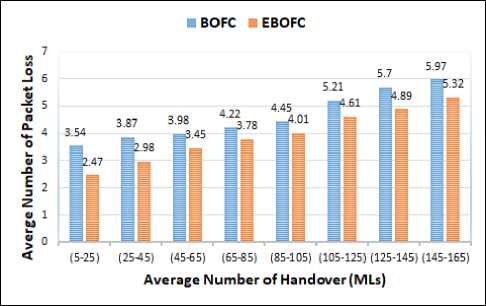
Fig.11. Average of Packets loss based on TL1 with SP1
Figure 11 shows the packet loss when it is calculated based on the TL1 and SP1. The average packet loss of BOFC approach during all handover procedure (MLs) is equal ≈ (4.6) packets and the average of packet loss in the EBOFC approach is ≈ (3.94) packets. The percentage of packet loss enhancement is about ≈ (15%) in the EBOFC approach.
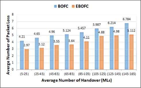
Fig.12. Average of packets loss based on TL1 with SP2
In figure 12 illustrates the scenario when the network load is increased where the packet loss is calculated using TL1 with SP2 (increasing in the mobile activity). The average packet loss of BOFC approach during all handover procedure (MLs) is equal ≈ (6.8) packets and the average packet loss in the EBOFC is ≈ (4.05) packets. The percentage of packet loss enhancement is about ≈ (40%) in the EBOFC approach.
Figure 11 and figure 12 show the effect of changing the (SP) set from SP1 to SP2 based on the same priority interval time (TL1). It is worth noting that the percentage of packet loss was enhanced from (15%) to (40%). Therefore, if the probability of (ML) event is increased and the probability (SL) is decreased, then the probability of hard handover will increase and hence the percentage of packet loss enhancement will increase.
To study the effect of decreasing the network load, both figure 13 and figure 14 use TL2. In figure 13, the packet loss is calculated using SP1, the average packet loss of BOFC approach during all handover procedure (MLs) is equal ≈ (3.12) packets per one handover procedure and the average of packet loss in the EBOFC is ≈ (2.89) per one handover procedure. The percentage of packet loss enhancement in our approach is about ≈(8%) in the EBOFC approach.
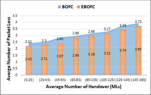
Fig.13. Average of packets loss based on TL2 with SP1
In figure 14, the packet loss is calculated using SP2, the average packet loss of BOFC approach during all handover procedure (MLs) is equal ≈ (3.9) packets and the average of packet loss in the EBOFC is (3.31) packets. The percentage of packet loss enhancement is about (15%) in the EBOFC approach.
Figure 13 and figure 14 show the effects of changing the (SP) set from SP1 to SP2 based on the same priority interval time (TL2). The percentage of packet loss enhancement is changed from (8%) to (15%). Therefore, if the probability of (ML) event is increased and the probability (SL) is decreased, then the probability of hard handover will increase and the percentage of packet loss enhancement will increase.
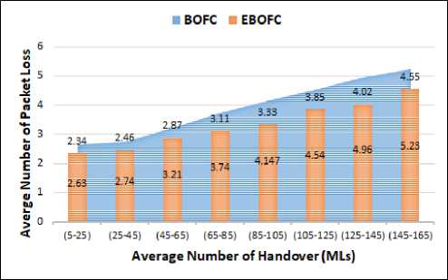
Fig.14. Average of packets loss based on TL2 with SP2
In General, when the network load is increased the number packet consequently will be increased regardless of the used approach (e.g. BOFC or the EBOFC). The experimental results showed that the number of packet loss in the EBOFC work is less than the packet loss in the BOFC approach. The enhancement ratio in the EBOFC approach is achieved in all network load cases.
-
V. Conclusions
This research proposed an extended scheme for overflow control based on BOFC approach (called EBOFC scheme). The new scheme exploits BOFC scheme functions and integrates both RNC and BS levels to reduce the number of packets loss during the inter-SGSN process. The EBOFC scheme buffers packets in both NRNC and NBS sets. Additionally, in BOFC scheme, packets are buffered in all NBSs in the active set if and only if all the NBS are controlled by the same SRNC. However, in EBOFC scheme, packets are buffered in all NBSs regardless if all NBSs are controlled by SRNC or NRNC. Both EBOFC scheme and the BOFC scheme use the same functions in the Intra-SGSN relocation (i.e. when the mobile moves from base station to other within the same SGSN region). Therefore, the percentage of packets loss in both schemes is approximately the same. The experimental results showed that the proposed EBOFC scheme achieved a better percentage of packets loss over similar approaches when the UE moves in overlapped regions in situations where different GGSN branches are used.
References An extended approach for enhancing packet-loss of inter-SGSN in 3G mobile networks
- Alberto Rico-Alvarino,Madhavan Vajapeyam, Hao Xu, Xiaofeng Wang, Yufei Blankenship, Johan Bergman, Tuomas Tirronen, Emre Yavuz, "An overview of 3GPP enhancements on machine to machine communications", IEEE Journals & Magazines, Volume: 54, Issue: 6, 2016.
- Vipin Balyan; Ben Groenewald, "UMTS and LTE interfaces utilization improvement with QoS in mobile communication systems", International Conference on Recent Advances and Innovations in Engineering (ICRAIE), 2016.
- Yasir; Ning Wu; Aamir Akhtar Siddiqui, "Performance comparison of KASUMI and hardware architecture optimization of f8 and f9 algorithms for 3g UMTS networks", 14th International Bhurban Conference on Applied Sciences and Technology (IBCAST), 2017.
- Piergiuseppe Bettassa Copet, Guido Marchetto, Riccardo Sisto, Luciana Costa, "Formal verification of LTE-UMTS and LTE–LTE handover procedures", Computer Standards & Interfaces, Pages 92-106, 2017.
- Bhavneet Dhindsa, "LTE interfaces and protocols", 2015 International Conference on Advances in Computer Engineering and Applications (ICACEA), Ghaziabad, India, 2015.
- M. Isabel Sanchez, Engin Zeydan, Antonio de la Oliva, A. Serdar Tan, Carlos J. Bernardos, "Mobility management: Deployment and adaptability aspects through mobile data traffic analysis", Computer Communications, Pages 3-14, Volume 95, 2016.
- Ai-Chun Pang, Yi-Bing Lin, Hsien-Ming Tsai, P. Agrawal, "Serving radio network controller relocation for UMTS all-IP network", IEEE Journal on Selected Areas in Communications, Volume: 22, Issue: 4, 2004.
- Mohammad Reza Pasandideh, Marc St-Hilaire, "Automatic planning of 3G UMTS all-IP release 4 networks with realistic traffic", Computers & Operations Research, Pages 1991-2003, Volume 40, Issue 8, 2013.
- Virginia Pilloni, Emad Abd-Elrahman, Makhlouf Hadji, Luigi Atzori, Hossam Afifi, "IoT_ProSe: Exploiting 3GPP Services for Task Allocation in the Internet of Things", Ad Hoc Networks, 2017.
- Lin, Lin and Chlamtac, “Overflow Control for UMTS High Speed Downlink Packet Access”, IEEE TRANSACTIONS ON WIRELESS COMMUNICATIONS, VOL. 3, NO. 2, 2004.
- Sok-Ian Sou, Hung-Yang Hsieh, "Modeling application-based charging management with traffic detection function in 3GPP", Computer Networks, Volume 91, Pages 625-637, 2015.
- Ye Ouyang; M. Hosein Fallah, "A performance analysis for UMTS packet switched network based on multivariate KPIs", Wireless Telecommunications Symposium (WTS), 2010.
- Jun Tsutsumi; Marten Seth; Arthur S. Morris III; R. Bogdan Staszewski; Gernot Hueber, “Cost-Efficient, High-Volume Transmission: Advanced Transmission Design and Architecture of Next Generation RF Modems and Front-Ends”, IEEE Microwave Magazine, Volume: 16, Issue: 7, 2015.
- George R. MacCartney; Theodore S. Rappaport, Study on 3GPP rural macrocell path loss models for millimeter wave wireless communications, IEEE International Conference on Communications (ICC), 2017.
- Fayezeh Ghavimi; Hsiao-Hwa Chen, "M2M Communications in 3GPP LTE/LTE-A Networks: Architectures, Service Requirements, Challenges, and Applications", IEEE Communications Surveys & Tutorials, Volume: 17, Issue: 2, 2015.
