An Improved Watermarking Scheme for Tiny Tamper Detection of Color Images

Author: Nader H. H. Aldeeb, Ibrahim S. I. Abuhaiba
Journal: International Journal of Image, Graphics and Signal Processing(IJIGSP) @ijigsp
Article in issue: 5 vol.5, 2013.
Free access
In many applications, images are sensitive to an extent such that any modification in it could lead to serious problems. For example, hiding any portion of a medical image could lead to a misdiagnosis. Thus, detecting forgery in images is a mandatory as well as being a legal and ethical duty. The main contribution of this paper is to propose a new Content Authentication (CA) watermarking scheme, which aims at detecting any modification, forgery, or illegal manipulation of images even if it is small. Our proposed scheme is a fragile, secure, and a reversible watermarking scheme. It generates the watermark uniquely using a messy model. The generated watermark is embedded accumulatively; to obtain spreading over the whole image area, and embedded homogeneously; to obtain a high quality watermarked image. Our proposed scheme is a development of a recently proposed watermarking scheme. Our proposed scheme surpassed its counterpart in terms of capacity, quality, watermark spreading, fragility, and embedding time. The payload of the host image increased from 81.71 % to 93.82 %. The minimum obtained PSNR value increased from 27.15 dB to 31.76 dB. The watermark spreading percentage, or the percentage of the protected pixels, is noticeably increased. Our proposed scheme is very sensitive to modifications anywhere in the image even if it is tiny. Finally, our proposed CA scheme has a faster embedding time than that of its counterpart. We obtained an average reduction in time equals 0.15 second.
Color Image Watermarking, Content Authentication, Forgery Detection, Reversible, Fragile
Short address: https://sciup.org/15012703
IDR: 15012703
Text of the scientific article An Improved Watermarking Scheme for Tiny Tamper Detection of Color Images
Published Online April 2013 in MECS DOI: 10.5815/ijigsp.2013.05.01
A huge amount of digital information is moving around the world by means of the rapid growth in Internet technology and digital media. Digital media offers several distinct advantages such as high quality, easy editing, and high fidelity copying. This ease, by which digital information can be manipulated and duplicated, has made publishers, authors, artists, and photographers afraid that their innovations and products going to be modified illegally or claimed by others. Therefore, we need a technique for verifying content’s integrity of the digital media.
Digital watermarking is a method of hiding information (watermark) into a host (cover) signal (image, audio, or video) so that the watermark can be detected or extracted later to make an assertion about the cover signal. Digital watermarking techniques initially used for limited intents, now it becomes a well-defined science with its own resourceful schemes. Presently, it is the core of many modern applications. To name a few amongst its innumerable applications, digital watermarking is employed in Copyright Protection (CP) [1], Content Authentication (CA) [2], Fingerprinting [3], Telemedicine or e-health [4], Copy Prevention or Control [5], Content Description [6], Secret Communication [7], and ID Card Security [8].
When digital watermarking is used for copyright protection the embedded watermark must survive against attacks, while when used for content authentication the embedded watermark should be fragile or easily broken. The fragility of the watermarking scheme refers to its sensitivity to attacks [9]. Thus, in content authentication schemes, the more fragility of the watermarking against attacks the more successful the watermarking algorithm.
In this paper, we propose a new digital watermarking algorithm, which has the ability of detecting any type of alteration that might infect images. In addition, it has the ability of locating the modified regions precisely with an accuracy reaches the level of a single pixel.
Many watermarking algorithms are proposed to solve the problems of content authentication. Each competes to accomplish higher fragility than others do. An intensive study and detailed analysis of the most promising proposed algorithms is performed, to find which of the proposed schemes can be adapted to meet our proposed algorithm requirements. According to their attractive properties (Secure, Reversible, and Easily Implemented); the idea of Poonkuntran and Rajesh algorithm [9] is chosen and developed to be used as a bases in building our proposed scheme.
The rest of this paper is organized as follows:
Section II presents a review of the necessary background required to implement our scheme effectively. Section III introduces related work for this paper. Section IV proposes and discusses the new scheme. Section V presents experimental results and analysis. Finally, section VI is dedicated for summary and conclusion.
-
II. BACKGROUND
-
A. Theoretical Model of Digital Watermarking System
Digital watermarking usually divided into two main processes: watermark embedding process and watermark extraction process.
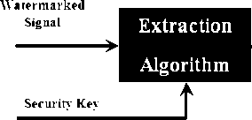
The watermark embedding process embeds the watermark into the host signal. The watermark and the host signal are the inputs of this process. The watermarked signal is the output of this process. In some watermarking systems, a security key is used as additional input for the embedding process; it adds a level of security to the watermarking process and makes the watermark more robust against attacks. Fig. 1 shows the watermark embedding process, which is adapted from [10].
Host Signal --------►
УУ atermark ------------*-
Securin’ Key
Embedding Algorithm
Watermarked
Signal

Figure 1: Watermark embedding process.
The watermark extraction process extracts the watermark from the watermarked signal. The watermarked signal is the basic input of this process, the output of this process is the extracted watermark. If the embedding process used a security key, the same key is needed in the extraction process. The extraction process is exactly the reverse of the embedding process. Other inputs may be needed based on which type of watermarking algorithms is applied. For example, in the CA and CP systems the original watermark is also needed as an input to the extraction process for comparing with the extracted one in order to determine whether the host signal is authentic or not. The comparison is performed using a comparator function, C∂, which is based on the correlation, C, of the two watermarks, W and W e , and the threshold, ∂. The comparison process can be represented mathematically as shown in (1) below.
C a (W,W)=, (1)
0, otherwise
Where, C is the correlation of W and W e , it is calculated as shown in (2) below.
C=
∑∑ i (( w ( i , i ) -mw )( we ( i , j ) -MWe ))
√∑∑j(w(i,i)-MW)2√∑∑j(we (i,j) -MWe)2
Where, M W and M We are the mean values of the original and the extracted watermarks respectively. Finally, Fig.2 shows the watermark extraction process, which is adapted from [10].
Extracted Watermark
Figure 2: Watermark extraction process.
-
B. Performance Measurements of a Watermarking Algorithm
1. Normalized Cross Correlation (NCC)
NCC is an important performance parameter in any extracting module. Sometimes, it is needed to have a robust watermarking algorithm. Robustness means to have approximately undistorted extracted watermark even if the watermarked image is subjected to attacks. The NCC is used to verify the robustness of the watermarking systems by expressing the comparability between the extracted watermark and the original watermark quantitatively [11]. NCC is defined as in (3) below [12].
NCC=
∑∑yW(X,У) W' (x,у)
Ne
EC=
N
-
4. Peak Signal to Noise Ratio (PSNR)
PSNR is used to measure how much the watermarked version of an image is similar to the original image. Suppose we have an image I and its watermarked version I’. Also suppose that the MSE values of the Red, Green, and Blue components are MSE R , MSE G , and MSE B respectively. The PSNR is defined as shown in (6) below:
PSNR (dB) = 10 log10 - (6)
( )/
Where, maxI is the maximum pixel value of the original image. Internationally, PSNR is measured in decibel units (dB), and the bigger the PSNR value the better the watermark conceals [11]. In general, the processed image is acceptable to the human eyes if its PSNR is greater than 30 dB [12]. At that level, the processed or watermarked image will be visually very close to the original, un-watermarked, image.
-
III. RELATED WORK
Hua et al. [13], proposed a fragile watermarking algorithm, which is based on both Discrete Wavelet Transform (DWT) and Discrete Cosine Transform (DCT) to achieve content integrity protection, CA, of color images. The original image’s brightness component is first three-discrete-wavelet decomposed. The sub-bands LL3 and LH3 are then extracted and divided into blocks. Then, DCT is applied to each block. A specific coefficient (namely, non-zero minimum value) in LH3’s block’s DCT is replaced by a corresponding coefficient (namely, non-zero minimum value) in LL3’s block’s DCT. Reverse DCT and DWT are done to get the watermarked image. Later, to detect whether the watermarked image has been tampered or not, those two replaced coefficients in each block are extracted and compared. If they are too close, then no tamper is detected in that block, otherwise, the block was tampered. Hence, the distortion will be located in each block independently.
In this work, the embedded watermark is represented by changing the LH3’s block’s DCT’s coefficient value by LL3’s block’s DCT’s coefficient value. Since the selected coefficients for replacement are independent and may have very different values (large in-between distance); replacement of one coefficient value by another (to have same values) will distort the original block’s quality and hence will distort the original image quality permanently.
Liew and Zain [14], proposed a reversible watermarking scheme for tamper detection and recovery of ultrasound grayscale images. Due to the characteristics of ultrasound images, they used four rectangles organized as a pyramid to locate Regions of Interest (ROI). The rest of regions are assumed as Regions of Non Interest (RONI). In the watermark embedding process, bits are embedded by replacing the LSBs of some ROI blocks with the watermark bits. The
LSBs, which were replaced in the watermark embedding process, are stored in the RONI for the reason of restoration of ROI to its original state. They used a mapping sequence locating the blocks from where bits are removed and where bits are stored in.
From our point of view, the used mechanism by Liew and Zain for the reversibility of original bits of ROI is inappropriate. By any small attack at the RONI the stored bits will be lost. Also, along with the limitation of their scheme to grayscale images, their proposed scheme is dedicated only to images with a pyramidal shaped ROI, particularly, ultrasound grayscale images.
Tian [15], proposed a reversible watermarking method for gray scale images based on difference expansion. In Tian’s work, the difference between each neighboring pixel values of the image is calculated. Some of the calculated differences are selected for difference expansion and watermark bit embedding. Only expandable differences are selected to avoid both overflow and underflow. The pixel’s pairing could be horizontally, vertically, etc. If it is found that the difference h is expandable, it is replaced by a new difference h’=2h+bit, where bit is the watermark bit to be embedded. A new pixel pair values are then calculated based on the new difference, h’. A location map of all expanded differences is created to be used as a guide in the watermark extraction stage. The size of the location map is equal to the number of differences or pixel pairs. A value of “1” is assigned in the location map to correspond to an expandable difference. Otherwise, a value of “0” is assigned. The location map of expanded difference numbers, the original values of the difference numbers, and the watermark itself will all be embedded into the host image.
The main drawback in Tian’s method is that extra information need to be embedded other than the watermark, this of course at the expense of the payload which can be embedded into the host image.
Poonkuntran and Rajesh [9], proposed a watermarking scheme for the authentication of color medical images. Their proposed scheme generates the watermark dynamically using a hybrid bi-stable messy system, which was used in [16], and based on the green color plan of the host image as a seed to the messy system. Bits of the generated watermark are embedded by expanding the expandable differences between the corresponding pixel pairs from Red and Blue color plans in a method called intra plan difference expansion, which was used in Tian’s scheme [15]. A location map is used to refer to the locations where embedding takes place. The location map is an image of binary pixels. Each pixel in the location map is set to one when the corresponding difference is expandable, otherwise that pixel is set to zero. In watermark extraction, the location map is checked to locate the previously embedded pixel pairs. The LSB of the difference of each located pair gives the corresponding embedded watermark bit. The most important point in Poonkuntran and Rajesh work is using the messy system; by which, the watermark is generated securely and uniquely to each image.
Generally, it is required to detect any modification in any location at the medical image even if it is tiny. We can obtain this high sensitivity to image tampering by allowing the watermark to cover whole the image area. Poonkuntran and Rajesh scheme is for the purpose of CA of medical images. But unfortunately, the difference between the color plans may be large to some extent leading to generate a non-expandable difference. Therefore, the generated watermark might not cover whole the image area. Thus, fragility is not enough high in Poonkuntran and Rajesh scheme. Image modifications might not be detected in all image locations.
Because it is secure, reversible, and easily implemented; we decided to improve the idea discussed in Poonkuntran and Rajesh work, solving its drawbacks, and finally use its improved version in our proposed CA watermarking scheme.
-
IV. PROPOSED SCHEME
-
A. Overview
In this paper we propose a CA watermarking scheme. It is a reversible, secure, and fragile watermarking scheme, which aims at detecting tampering of color images even if the tamper is tiny. Our proposed scheme is a development of the technique proposed by Poonkuntran and Rajesh [9]. Their proposed scheme aimed at authenticating medical images, especially fundus images. They claim that their proposed scheme is very sensitive to the jittering, geometrical, and various filtering attacks. Actually, we performed an intensive study, implementation, and tests to their proposed scheme. We found two drawbacks in their proposed scheme:
-
1. It is required to detect any modification in medical images even if it is small and either if it is intentional or not. In such cases of modification, the attacker is interested in small portions of the watermarked image, usually are certain important details of the image. The only way to survive such attacks is by allowing the watermark to spread over the whole image’s area. But unfortunately, that is not the situation in the scheme proposed by Poonkuntran and Rajesh.
-
2. The way of embedding followed by Poonkuntran and Rajesh will generate a watermarked image with a distorted quality. The reason is that, their scheme is based on the difference between pixels among two different color plans, which is generally not a small quantity. Based on that large difference to embed each single watermark bit, Poonkuntran and Rajesh substitute a pair of pixels among two different color plans with a new completely different pixels pair. Therefore, using large watermark sizes in Poonkuntran and Rajesh scheme will introduce watermarked images having low PSNR, and hence, generate a distorted image quality.
These two drawbacks are addressed in our proposed watermarking scheme.
-
B. The Conceptual Model of the Proposed CA Watermarking Scheme
The architecture of the proposed scheme is summarized in Fig. 3. Decomposing the original image is the first process in our model. Then, a specific color plan among the three is chosen as a base for generating the watermark, W, to be embedded. According to [9], in some color images; the Green channel contains more important details than other channels. Thus, in our CA scheme, the Green color plan is chosen as a reference plan for the watermark generation process.
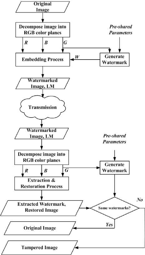
Figure 3: The conceptual model of the proposed CA watermarking scheme.
One of the other two color plans can be used to embed the generated watermark. In our scheme, the Red color plan is used as a host for embedding the generated watermark in a method called inter-plan difference expanding. After watermark embedding, the three color plans are all used to reconstruct the watermarked image. The watermarked image and the Location Map (LM) are the outputs of the embedding process. Since only a portion of image locations will be used for embedding, the LM is one-bit bitmap carrying information about the selected embedding locations.
At the other end, the receiver can make an assertion about the integrity of the received image. Firstly, the three color plans are obtained by decomposing the received watermarked image. Secondly, the watermark generation process is also conducted here based on the green color channel as before. Finally, the watermarked color plan, Red color plan, along with Green and Blue color plans are brought to the watermark extraction and image restoration process. The LM will be used in this process as a guide to refer to the locations where the watermark was embedded. The extracted watermark is then compared with the generated one. If a match is found, the restored image is the original image; otherwise, it is assumed a tampered image with a precise tampering location. The following parts of this section will discuss the core processes in our proposed CA scheme.
-
C. The Messy Watermark Generation Process
Using a messy system has several benefits:
-
1. The system complexity alone provides a secure watermark generation, especially when using a security key and parameters those are unknown by others.
-
2. Although it is deterministic, the behavior of the messy system appears random.
-
3. Based on the reference color plan of the host image, the watermark is generated dynamically. In other words, a unique watermark is generated for each different image.
In our proposed CA watermarking scheme, the watermark is generated using a messy, chaotic, system shown in (7), which was also used in Poonkuntran and Rajesh scheme [9], and Ni et al. scheme [16]. The input variable, x n , refers to the current input of the system, and x n+1 refers to the output of the messy system, which may be used as the next input to the system.
x =f(x )=4sin ( x - 2․5 ) (7)
As stated before, the green color plan will be used to generate the watermark. Therefore, it is used as a seed to the messy system seen in (7). Generally, each pixel value will iteratively enter the system until obtaining a sequence of values with a certain messy status, which will be discussed later. However, before entering the messy system, each pixel value is first converted to a corresponding initial value using (8) below.
seq(k,0)= а∗floor* ( ) +∗2 + b∗pos+с∗key (8)
Where, seq(k, 0) refers to the initial value of the kth pixel, s(k) is the value of kth pixel. Also, a, b, and c are predefined constants, l refers to the embedding depth, pos refers to the position index of the kth pixel, and key is the security key used for securing the watermarking method, it could be any positive integer value. The variable pos is used to achieve the requirement that, equal pixels on different positions in the same reference color plan should produce different messy sequences. The constants a, b, and c are used to fulfill the requirement that, equal pixels at the same positions of different reference color plans should generate different messy sequences. To enable each pixel to contribute significantly in calculating its initial value, the embedding depth, l, is set to a small quantity. These parameters are pre-shared among legitimate parties, and it could be changed by their agreement.
Now, to obtain the messy sequence of the kth pixel, we substitute its initial value, seq(k,0), for x n in (7) to obtain seq(k,1), which is used as a new input to the same messy system to obtain seq(k,2), and so on. This process is repeated a reasonable number of iterations, I, for the kth pixel until attaining the messy status. The generated sequence of the kth pixel is referred to as seq(k,i), i=1,2,3,4,…..,I. It is evident that the generated sequence contains a floating numbers. The sequence is then converted to a binary sequence b_seq(k,i) using (9). Where, T is a threshold set to 8/3, to attain approximately equal number of 0’s and 1’s according to the authors of [9].
b_seq(k,i)=,1, seq(k,i)> (9) 0, otherwise
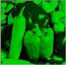
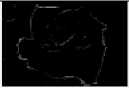
In the binary representation of sequences, the probability of having equal binary sequences is high if the length of the sequence is very small. Therefore, in our work, we defined the messy status as the situation where for a given set of generated binary sequences the probability of encountering equal consecutive sequences is as small as possible. After some experiments, we observed that we could attain a messy status when the length of the sequences is not less than 5 bits. Thus, for low complexity we have chosen I to be 5. The generated binary sequence is then summarized to one bit by applying XOR operation. The generated bit is the messy watermark bit for the kth pixel. The same procedure is repeated with the rest of pixels in the reference color plan, Green plan, to obtain the binary watermark, W, for entire the image as shown in Fig. 4.

(a)
(b)

(c)
Figure 4: Watermark generation using messy system. (a) Original image, (b) Reference color plan, (c) Generated watermark.
-
D. The Watermark Embedding Process
A new embedding strategy is proposed aiming to solve the previously mentioned drawbacks of Poonkuntran and Rajesh scheme. It will be conducted to embed a watermark based on the spatial domain of the original image. It is designed homogenous, aiming at producing a high quality, undistorted, watermarked image. To obtain homogeneity we embed the watermark by expanding the differences between the neighboring pixels at the same color plan in a method called interplan difference expanding rather than expanding the difference between pixels from different color plans as in Poonkuntran and Rajesh scheme. We can choose either the Red or Blue color plan for embedding the watermark. The Red color plan is chosen for watermark embedding in our work. Inter-plan difference expanding is performed by employing the integer transform, IT, and its inverse, IIT, which will be discussed later.
In addition to homogeneity, our proposed embedding strategy is an accumulative strategy, which aims at wide and non-uniform spreading of the embedded watermark; and hence, it will sense any modifications in the watermarked image, even if it is very small. To obtain an accumulative watermark embedding, the watermark embedding process is divided into three stages; namely, vertical, horizontal, and diagonal. Each stage is responsible for embedding some selected watermark bits by expanding the difference between pixels in a predefined direction. The detailed steps of the embedding process are illustrated in Algorithm 1. This algorithm will perform an accumulative watermark embedding by running the three embedding stages one after another.
Algorithm 1: The embedding process of the proposed CA scheme.
Purpose: Accumulative and homogeneous watermark embedding.
Input: Red , Green , and Blue color plans of the original image,
Binary Watermark, W .
Output: The watermarked image, WI , and the location map, LM .
Procedure:
-
a) Define LM , an empty matrix of size = size of the Red color
plan.
-
b) Based on the Red color plan and the watermark, W , the vertical embedding stage generates the vertical embedded component, VEC , and modifies the location map, LM , accordingly.
-
c) Based on the vertical embedded component, VEC , and the watermark, W , the horizontal embedding stage generates the vertical and horizontal embedded component, VHEC , and modifies the location map, LM , accordingly.
-
d) Based on the vertical and horizontal embedded component, VHEC , and the watermark, W , the diagonal embedding stage generates the vertical, horizontal, and diagonal embedded component, VHDEC , and modifies the location map, LM , accordingly.
-
e) The watermarked image, WI , is generated by combining the vertical, horizontal, and diagonal embedded component, VHDEC , along with the Green and Blue color plans.
-
255. Let d is the difference between p1 and p2, and m is their average. The IT defines a one-to-one correspondence between (p1, p2) and (m, d). The integer transform to obtain (m, d) from (p1, p2) is defined as shown in (10) and (11) below.
End
The three embedding stages of the proposed embedding process share the same embedding mechanism which is inter-plan difference expansion based on integer transform, IT, and its inverse, IIT.
Watermark embedding by inter-plan difference expanding
Suppose that we have a pixel pair (p1, p2), such that p1 and p2 are both integers and satisfying 0 ≤ p1 , p2 ≤
m= ⌊ 2 ⌋ (10)
d = p1 - p2 (11)
Where, ⌊v⌋ is the floor operator, which returns the greatest integer less than or equal v. The inverse integer transform to obtain (p1, p2) from (m, d) is defined as shown in (12) and (13) below.
p1 = m+ ⌊ ⌋ (12)
p2 = m- ⌊ I ⌋ (13)
To embed a watermark bit by expanding the difference between p1 and p2 a new difference d’ is generated as seen in (14), which is equivalent to appending the bit to the binary representation of d, such that bit becomes the new LSB.
d = 2 ∗ ԁ+bit
That new difference, d’, along with the mean, m, will be used to generate a new pixels pair, (p1’, p2’), to replace the old one using the IIT shown in (12) and (13). But before generating the new pixels pair, the suitability of that new difference is checked to avoid both overflow and underflow of the new calculated pixels, i.e., to avoid having pixel values those fall outer the interval [0,255]. Particularly, the difference, d, is expandable if and only if the new difference, d’, satisfies either part of (15), which is derived by bounding p1 and p2 of (12) and (13) respectively; such that 0 ≤ p1, p2 ≤ 255.
|d′| ≤ 2 ∗(255-m), if 128≤ m ≤ 255
{|d′| ≤ (2∗m) +1, if 0≤ m ≤ 127
Using inter-plan difference expanding, each bit of the generated watermark, W, will be embedded by expanding the difference between a two selected neighboring pixels from the Red color plan. The three embedding stages share the task of embedding whole watermark bits. Each stage will be responsible for embedding some reserved watermark bits using its own predetermined pixels pairing direction. At each stage run, the previously generated watermarked plan is assumed as a new host plan for the current stage. Now, we will discuss each stage individually.
-
a) The proposed vertical embedding stage
It is the first embedding stage in our proposed watermark embedding process. The Red color plan, the generated binary watermark, W, and the location map, LM, are the inputs to this stage. The vertical embedded component, VEC, is the output of this stage. This stage is responsible for embedding some selected watermark bits, each of which is embedded by expanding the difference between two vertically neighbored pixels.
The detailed steps of the vertical embedding stage are illustrated in Algorithm 2.
Algorithm 2: The vertical embedding stage of the proposed CA scheme.
Purpose: Vertical embedding of some selected watermark bits.
Input: Red color plan, Binary Watermark, W , and Location Map, LM .
Output: Vertical Embedded Component, VEC .
Procedure: // Indexes: i for columns and j for rows
FOR i = 0 ; i < Width ; i++
FOR j = 0 ; j < Height – 1 ; j += 2
V Calculate the difference, d = VEC [i, j] - VEC [i, j+1]
V Calculate the new difference, d’ = 2( d ) + W [i, j]
IF d’ satisfies (15), i.e. d is expandable
V Update the location map as: LM [i, j] =1
V Replace the pixels pair ( VEC [i, j], VEC [i, j+1]) with a new pixels pair, using IIT, which is based on the new difference, d’ , and the average, m , of the pair, as seen in (12) and (13).
END IF
END FOR
END FOR
END
As seen in Algorithm 2, the initial values and the way of incrementing the variables i and j enforces vertical moving through the Red color plan, and hence, generating vertical pixels pairing. Also, the variables i and j are responsible for relating each generated pixel pair with its corresponding watermark bit. Finally, the location map, LM, is updated just before each bit embedding takes place.
-
b) The proposed horizontal embedding stage
It is the second embedding stage in our proposed watermark embedding process. The same watermark, W, and location map, LM, are also used as inputs to this stage. But, the host color plan is changed in this stage. The new host color plan is the output of the vertical embedding stage; namely, VEC. The output of this stage is VHEC, which will carry both vertical and horizontal embedding. The detailed steps of the horizontal embedding stage are illustrated in Algorithm 3, which embeds some selected watermark bits by expanding the difference between horizontally neighbored pixels through the vertical embedded component, VEC.
Algorithm 3: The horizontal embedding stage of the proposed CA scheme.
Purpose: Horizontal embedding of some selected watermark bits.
Input: Vertical Embedded Component, VEC , Watermark, W ,
Location Map, LM .
Output: Vertical and Horizontal Embedded Component, VHEC .
Procedure: // Indexes: i for columns and j for rows
FOR i = 0 ; i < Width – 1 ; i += 2
FOR j = 1 ; j < Height; j += 2
V Calculate the difference, d = VHEC [i,j] - VHEC [i+1, j]
V Calculate the new difference, d’ = 2( d ) + W [i, j]
IF d’ satisfies (15), i.e. d is expandable
V Update the location map as: LM [i, j] =1
V Replace the pixels pair ( VHEC [i, j], VHEC [i+1, j]) with a new pixels pair, using IIT, which is based on the new difference, d’ , and the average, m , of the pair, as seen in (12) and (13)
END IF
END FOR
END FOR
END
-
c) The proposed diagonal embedding stage
It is the last embedding stage in our proposed watermark embedding process. The output of the previous horizontal embedding stage; namely VHEC, is the new host color plan of this stage. The watermark, W, and location map, LM, are also used as inputs to this stage. Along with the previously embedded bits, the VHEC will be embedded with the rest of bits those were not embedded until now. The output of this stage is VHDEC, which will carry vertical, horizontal, and diagonal embedding. The detailed steps of the diagonal embedding stage are illustrated in Algorithm 4. As seen in the algorithm, it embeds bits by expanding the difference between diagonally paired pixels of the vertical and horizontal embedded component, VHEC.
As seen in Algorithm 1, the watermarked image, WI, is obtained by combining the original Green and Blue color plans with the accumulatively embedded component, VHDEC, which is the output of Algorithm 4. Also, by the completion of the three embedding stages the location map, LM, is obtained. Finally, it is worth mentioning that embedding by inter-plan difference expansion leads to a larger number of expandable differences than those obtained when using intra-plan difference expansion, which was used in Poonkuntran and Rajesh scheme. That because now pairing is based on neighboring pixels at the same color plan, which leads to smaller differences. This also solves the second drawback of their scheme, low PSNR, because we replace old pixels with new pixels those are very close to the old ones.
Algorithm 4: The diagonal embedding stage of the proposed CA scheme.
Purpose: Diagonal embedding of some selected watermark bits.
Input: Vertical and Horizontal Embedded Component, VHEC ,
Binary Watermark, W , and Location Map, LM .
Output: Vertical, Horizontal, and Diagonal Embedded Component, VHDEC .
Procedure: // Indexes: i for columns and j for rows
FOR i = 1 ; i < Width ; i += 2
FOR j = 1 ; j < Height; j += 2
V Calculate the difference, d = VHDEC [i, j]- VHDEC [i-1, j-1] V Calculate the new difference, d’ = 2( d ) + W [i, j]
IF d’ satisfies (15), i.e. d is expandable
V Update the location map as: LM [i, j] =1
V Replace the pixels pair ( VHDEC [i, j], VHDEC [i-1, j-1 ]) with a new pixels pair, using IIT, which is based on the new difference, d’ , and the average, m , of the pair, as seen in (12) & (13)
END IF
END FOR
END FOR
END
-
E. The Watermark Extraction and Image Restoration Process
To coincide with the new former proposed watermark embedding process, a new process is proposed. Namely, watermark extraction and image restoration process. It aims to extract the previously accumulatively embedded watermark simultaneously with removing the effect of the embedded bits. The detailed steps of the watermark extraction and image restoration process are illustrated in Algorithm 5. As seen in the algorithm, the Red, Green, and Blue color plans of the watermarked image along with the location map, LM, which was constructed during the embedding process are inputs to the watermark extraction and image restoration process. Three stages are employed to extract then to remove the watermark which was embedded accumulatively in the Red plan. Each stage is responsible for detecting the watermark bits those were embedded in a specific direction and also it performs a restoration from that embedding. The order of the three stages is reverse to that followed by the embedding process. In other words, here we start with the diagonal direction where it is the last handled direction in the watermark embedding process. Finally, the restored image, RI, and the extracted watermark, EW, are the outputs of this process.
Algorithm 5: Watermark extraction and image restoration process of the proposed CA watermarking scheme.
Purpose: Watermark detection and image restoration
Input: The color plans Red , Green , and Blue ; and the Location Map, LM .
Output: The Restored Image, RI , and the Extracted Watermark, EW .
Procedure:
-
a) Initialize VHDEC = Red
-
b) Based on the accumulatively embedded component, VHDEC , and the location map, LM , the diagonal extraction and restoration stage extracts the diagonally embedded bits and modifies the extracted watermark, EW , accordingly. Then it restores from the diagonal embedding and generates the vertical and horizontal embedded component, VHEC .
-
c) Based on the vertical and horizontal embedded component, VHEC , and the location map, LM , the horizontal extraction and restoration stage extracts the horizontally embedded bits and modifies the extracted watermark, EW , accordingly. Then it restores from the horizontal embedding and generates the vertical embedded component, VEC .
-
d) Based on the vertical embedded component, VEC , and the location map, LM , the vertical extraction and restoration stage extracts the vertically embedded bits and modifies the extracted watermark, EW , accordingly. Then it restores from the vertical embedding and generates the restored component, RC .
-
e) The restored image, RI , is generated by combining the restored component, RC , along with the Green and Blue color plans.
END
Now, we discus each stage of the proposed watermark extraction and image restoration process individually.
-
a) The proposed diagonal extraction and restoration stage
This stage is responsible for both detecting and removing the diagonally embedded watermark bits from the vertically, horizontally, and diagonally embedded component, VHDEC, which is the Red component of the watermarked image.
The detailed steps of this stage are illustrated in Algorithm 6. The algorithm first searches for a diagonal pair for which the corresponding location map, LM, value is 1, i.e., the diagonal pair was previously embedded. Then it extracts the embedded bit using (16), which finds the LSB of the pair difference, d’. Then, it restores from the diagonal embedding of that bit. Particularly, the restoration is simply replacing the current pixels pair with the old one, using (12) and (13) of the IIT, which is based on the old difference, d, and the average, m. The old difference, d, can be obtained based on the new difference, d’, using (14).
Algorithm 6: The diagonal extraction and restoration stage of the proposed CA scheme.
Purpose: Detecting and removing the watermark bits those were embedded diagonally.
Input: The vertical, horizontal, and diagonal embedded component,
VHDEC , and the location map, LM .
Output: The vertical and horizontal embedded component, VHEC , and the extracted watermark, EW , which will only have the bits were embedded diagonally.
Procedure: // Indexes: i for columns and j for rows
FOR i = 1 ; i < Width ; i += 2
FOR j = 1 ; j < Height; j += 2
Take the diagonal pixels Pair = ( VHEC [i, j] , VHEC [i-1, j-1] )
IF LM [i, j] ==1, i.e., The Pair was previously embedded Extraction:
V Calculate the new difference, d’ = VHEC [i, j] - VHEC [i-1, j-1]
V Based on the new difference, d’ , and using (16), extract the diagonally embedded watermark bit as: EW [i, j]= ( d’ % 2)
Restoration:
V Based on the new difference, d’ , use (14) to calculate the old difference, as = ⌊ ⌋ .
V Using (10) of the IT, calculate the average, m , of the current Pair .
V Based on the old difference , d , and the average, m , apply the IIT in (12) and (13), to get a new pair to replace the current Pair.
END IF
END FOR
END FOR
END bit=(d% 2) (16)
After the completion of this sage; the extracted watermark, EW, will only have the watermark bits, those were embedded diagonally. Therefore, the same extracted watermark parameter, EW, will also pass to the next two stages to obtain the full extracted watermark, which will have the diagonal, horizontal, and vertical bits.
-
b) The proposed horizontal extraction and restoration stage
It is the second stage in the extraction and restoration process of our proposed CA watermarking scheme and it is responsible for both detecting and removing the horizontally embedded watermark bits from the plan previously generated by the diagonal extraction and restoration stage, namely, vertical and horizontal embedded component, VHEC . The detailed steps of this stage are illustrated in Algorithm 7.
Algorithm 7: The horizontal extraction and restoration stage of the proposed CA scheme.
Purpose: Detecting and removing the watermark bits those were embedded horizontally.
Input: The vertical and horizontal embedded component, VHEC, and the location map, LM.
Output: The vertical embedded component, VEC , and the extracted watermark, EW , which will have both the diagonally and horizontally embedded bits.
Procedure: // Indexes: i for columns and j for rows
FOR i = 0 ; i < Width – 1 ; i += 2
FOR j = 1 ; j < Height ; j += 2
Take the horizontal pixels Pair = ( VEC [i, j] , VEC [i+1, j] )
IF LM [i, j] ==1, i.e., The Pair was previously embedded Extraction:
V Calculate the new difference, d’ = VEC [i, j] - VEC
[i+1, j].
V Based on the new difference, d’ , and using (16), extract the horizontally embedded watermark bit as: EW [i, j]= ( d’ % 2).
Restoration:
V Based on the new difference, d’ , use (14) to calculate the old difference, as = ⌊ ⌋ .
V Using (10) of the IT, calculate the average, m , of the current Pair .
V Based on the old difference , d , and the average, m , apply the IIT in (12) and (13), to get a new pair to replace the current Pair.
END IF
END FOR
END FOR
END
-
c) The proposed vertical extraction and restoration stage
It is the last stage in the extraction and restoration process of our proposed CA watermarking scheme. It is responsible for both detecting and removing the vertically embedded watermark bits from the vertical embedded component, VEC, which was generated by the previous stage, namely, horizontal extraction and restoration stage. The detailed steps of the vertical extraction and restoration stage are illustrated in Algorithm 8. The outputs of this stage are the restored component, RC, and the extracted watermark, EW. As stated in Algorithm 5, shown before, the restored image, RI, is generated by combining the restored component, RC, along with the Green and Blue color components. If we assumed that the watermarked image in not modified; then the restored image, RI, is identical to the original un-watermarked image.
Algorithm 8: The vertical extraction and restoration stage of the proposed CA scheme.
Purpose: Detecting and removing the watermark bits those were embedded vertically.
Input: The vertical embedded component, VEC, and the location map, LM.
Output: The restored component, RC , and the extracted watermark, EW , which will have the diagonally, horizontally, and vertically embedded bits.
Procedure: // Indexes: i for columns and j for rows
FOR i = 0 ; i < Width ; i ++
FOR j = 0 ; j < Height – 1 ; j += 2
Take the vertical pixels Pair = ( RC [i, j] , RC [i, j+1] )
IF LM [i, j] ==1, i.e., The Pair was previously embedded Extraction:
V Calculate the new difference, d’= RC [i,j] - RC [i, j+1].
V Based on the new difference, d’ , and using (16), extract the horizontally embedded watermark bit as: EW [i, j]= ( d’ % 2).
Restoration:
^ Based on the new difference, d’ , use (14) to calculate the old difference, as = ⌊ ⌋ .
-
^ Using (10) of the IT, calculate the average, m , of the current Pair .
-
^ Based on the old difference , d , and the average, m , apply the IIT in (12) and (13), to get a new pair to replace the current Pair.
END IF
END FOR
END FOR
END
-
V. EXPERIMENTAL RESULTS and analysis
Since our proposed scheme is a development of Poonkuntran and Rajesh scheme [9], we implemented their proposed scheme then we conducted different comparisons to evaluate our proposed scheme relative to their scheme. All tests are performed using a laptop running windows XP operating system, with a 2 GHz core 2 duo processor, 2 GB memory, and 384 MB display adapter. Matlab 7.8 and Visual Studio 2011 are the main software components used in our work.
The broad goal of our proposed schemes is to protect color images; therefore, a general purpose image database is obtained, which includes 1000 color images, those are given in IPEG format, with size 384 x 256 or 256 x 384. This database was previously used in [17], and we downloaded it from [18]. Database images are grouped into ten categories; including, African people, Beach, Buildings, Cars, Dinosaurs, Elephants, Flowers, Houses, Mountains, and Food. Also, because our proposed schemes may be directed to medical applications; a set of 50 colored medical images is established and joined to the aforementioned database under a new category named Medical. This medical set is obtained randomly from the Science Photo Library [19] and given in JPEG format in RGB color space. Therefore, our proposed schemes are evaluated using a dataset contains 1050 samples.
-
a) Comparing the Embedding Capacity
Each sample in our dataset is embedded by the watermark which is generated using the messy system which is based on the green component of the sample. Watermark embedding is performed using Poonkuntran and Rajesh scheme on the one hand and using our proposed CA scheme on the other hand. The percentage of the embedded bits at each sample is recorded. The average of that percentage is determined for each image category. Table 1 summarizes the obtained results for both schemes.
Table 1: Comparing the average embedding capacity between Poonkuntran and Rajesh scheme and our proposed scheme.
|
Category Name |
Using P. and R. scheme |
Using our proposed scheme |
|
African people |
89.24 |
96.07 |
|
Beach |
85.93 |
95.09 |
|
Buildings |
86.82 |
92.24 |
|
Cars |
75.38 |
86.64 |
|
Dinosaurs |
93.67 |
97.04 |
|
Elephants |
89.82 |
95.96 |
|
Flowers |
72.69 |
98.01 |
|
Houses |
88.06 |
92.80 |
|
Mountains |
86.77 |
94.52 |
|
Food |
66.09 |
92.57 |
|
Medical |
64.28 |
91.03 |
|
Average |
81.71 |
93.82 |
As seen in Table 1, the average embedding capacity for all image categories is 81.71% when using Poonkuntran and Rajesh scheme, and is 93.82% when using our proposed scheme. Therefore, for each introduced watermark to our proposed scheme, about 90 % of the watermark bits will be embedded, while, for each introduced watermark to their proposed scheme, about 80 % of the watermark bits will be embedded.
The interpretation for this increase at the embedding capacity in our proposed scheme is due to the use of inter-plan difference expansion rather than using intraplan difference expansion for watermark embedding. In using inter-plan difference expansion we embed each watermark bit by expanding the difference between two neighboring pixels, which are naturally highly correlated. This leads to a small difference which is mostly expandable. In other words, the new generated pixels, based on that small difference, will remain in the interval [0, 255]. And hence, using inter-plan difference expansion, leads a larger amount of expandable differences than those obtained when using intra-plan difference expansion, as in Poonkuntran and Rajesh scheme.
Finally, Poonkuntran and Rajesh mentioned that the embedding capacity of their scheme can be increased by using a multilayer difference expansion. Means, the same pairs of pixels are selected for further data embedding. But, it is worth mentioning that this solution can also further increases the embedding capacity of our proposed CA scheme. Thus, for a fair comparison, our recorded results are all based on a single layer embedding for both schemes. Means, each pixels pair is used only once.
-
b) Comparing the Effect of Watermark Embedding on the Host Image
Sometimes, the presence of a watermark in the host image might distort its quality. Therefore, in this section, the quality of the watermarked image is our main concern. The PSNR, seen in (6), is used as a measurement of the quality of the watermarked image. Particularly, PSNR is used to measure how much the watermarked image is similar to the original, unwatermarked, image.
Each of the 1050 samples in our dataset is watermarked by its generated watermark using either of the two watermarking schemes. But because the quality, PSNR, is proportional with the watermark size; for fair comparisons, the size of the watermark is fixed at both schemes for each sample. The quality, PSNR, of each watermarked sample is calculated and recorded. Also, the average PSNR is calculated per each category. Table 2 shows the obtained results of this experiment.
Table 2: Comparing the quality of the watermarked image for both Poonkuntran and Rajesh scheme, and our proposed scheme.
|
Category Name |
Average PSNR (dB), using P. and R. scheme |
Average PSNR (dB), using our proposed scheme |
|
African people |
28.93 |
32.82 |
|
Beach |
27.72 |
33.80 |
|
Buildings |
28.90 |
31.76 |
|
Cars |
30.48 |
32.62 |
|
Dinosaurs |
32.52 |
35.55 |
|
Elephants |
27.15 |
32.67 |
|
Flowers |
31.66 |
40.38 |
|
Houses |
29.30 |
32.04 |
|
Mountains |
29.02 |
33.70 |
|
Food |
27.85 |
33.32 |
|
Medical |
29.60 |
36.29 |
|
Average |
29.37 |
34.09 |
As seen in the table, for each category, our proposed scheme has higher average PSNR than that obtained using Poonkuntran and Rajesh scheme. Also, over all sample categories our proposed scheme has an average PSNR equals 34.09 dB while it is 29.37 dB for Poonkuntran and Rajesh scheme, which is under the level of acceptable degradation, 30 dB. Thus, we conclude that Poonkuntran and Rajesh scheme fails to generate high quality watermarked images, especially, when the watermark size is large. This contrasts with the fact that, large watermark size is a mandatory issue in CA watermarking schemes. Finally, in our proposed scheme we obtained a minimum PSNR of 31.76 dB, which is 4.61 dB larger than the minimum PSNR of 27.15 dB obtained by using their scheme.
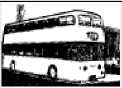
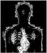
An example demonstrating how the watermarked image is affected when embedded by a large watermark size using Poonkuntran and Rajesh scheme in one hand and using our proposed CA scheme on the other hand is shown in Fig. 5 below.

Figure 5: Comparing the quality of the watermarked image (a) Original image. (b) Watermarked image using Poonkuntran and Rajesh scheme, PSNR= 25.60. (c) Watermarked image using our proposed scheme, PSNR= 35.75.
87.8%
99.01%
In this experiment, the original un-watermarked sample, shown in part (a) of the figure, is embedded by a watermark of size 90204 bits. A highly distorted watermarked image with PSNR= 25.60 dB is generated when using Poonkuntran and Rajesh scheme, as seen in part (b) of the figure. While, a high quality watermarked image, seen in part (c) with PSNR= 35.75 dB, is obtained when using our proposed watermarking scheme. Due to lack of quality; looking at part (b) one may erroneously think of a presence of a new disease. Finally, the PSNR obtained using our scheme is larger than that obtained when using their scheme by 10.15 dB. This increase of the quality of the watermarked images using our proposed scheme is due to the homogeneity of its embedding strategy, by which, pairing is based on neighboring pixels at the same color plan rather than different color plans. This leads to smaller differences and hence watermark embedding is performed by replacing old pixels with new pixels those are very close to the old ones.
-
c) Comparing Watermark Spreading
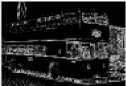
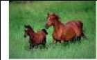
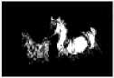
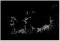
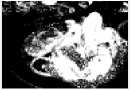
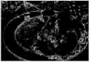
The only way to survive the attacker who is interested in a certain small important portions of the watermarked images is by allowing the watermark to spread over whole image area. Whenever the watermark spreads enough the ability to detect modifications anywhere is increased as well as the fragility of the watermarking scheme increased. This part is dedicated to compare the spreading of the watermark when being embedded using Poonkuntran and Rajesh scheme from one side and when using our proposed watermarking scheme from the other side. At this experiment, each of a five randomly selected samples from our dataset is embedded by the maximally possible watermark size using either of the two watermarking schemes. The watermark spreading degree is captured for each watermarking scheme and listed in Table 3 below. The watermark spreading degree is expressed by referring to the embedded locations at the host image. Note that, the embedded locations are represented by black color while non-embedded locations are left white. Also, the percentage of the embedded locations, (Total number of embedded locations/ Total number of image locations), is mentioned under each watermark spreading image.
Table 3: Comparing the watermark spreading using both Poonkuntran and Rajesh scheme, and our proposed scheme.
P. and R. Embedded Locations
Original Image

45.61%
Sample 1

Sample 2

46.51%
Proposed Scheme Embedded Locations
Sample 3 ь^у -у
90.2%
97.22%


63.56%
91.17%
(a) (b) (c)

(d) (e)
Figure 6: (a) Original image. (b) Watermarked image using P. and R scheme, attacked. (c) Watermarked image using the proposed scheme, attacked. (d) Watermarks error image of P. and R. scheme. (e) w atermarks error image of the proposed scheme .
Sample 4
Fj
Sample 5 Average
86.49%
93.68%
66.47 %
93.78 %
As seen in the table, the average percentage of the watermark spreading over all the watermarked images using Poonkuntran and Rajesh scheme is 66.47 %. Thus, only about 66.47 % of pixels of the watermarked image using Poonkuntran and Rajesh scheme are protected. Whereas, the average percentage of the watermark spreading over all the watermarked images using our proposed scheme is 93.78 %, which is the percentage of the protected pixels using our proposed CA scheme. Generally, the percentage of the watermark spreading varies from one image to the other, based on the amount of expandable locations found on it.
Actually, the vulnerability of the watermarking scheme is not only on the limitation of the watermark spreading but also related to where the watermark is concentrated. In protecting images of valuable contents, watermarks need to spread over whole image’s area or at least concentrate at valuable positions of the image. In view of the foregoing; some of the aforementioned watermarked samples using Poonkuntran and Rajesh scheme are assumed as not protected yet. Take for example, Sample 2, in which the watermark is concentrated at the background of the sample. Therefore, any alteration on the un-watermarked space will not be detected. Thus, this watermarking is useless.
Practically, Fig. 6 (a) shows an original image, (b) shows a modified watermarked version of (a) using Poonkuntran and Rajesh scheme, and (c) shows a modified watermarked version of (a) using our proposed CA scheme. The error image between the generated and the extracted watermarks in Poonkuntran and Rajesh scheme is zero anywhere, and hence, it does not sense the modifications as seen in (d). While, the modifications are detected precisely using our proposed scheme as seen in (e). The failure to detect this attack in Poonkuntran and Rajesh scheme is due to the limited embedding locations rather than being spread as in our proposed scheme. Thus, we can say that our proposed scheme is exclusive in detecting small modifications.
d) Comparing the Fragility against Attacks
Fragile watermarks can provide information about image completeness [20]. In this section, we compare the degree of fragility of Poonkuntran and Rajesh scheme with that of our proposed scheme. The results obtained in this experiment are shown numerically in Table 4.
Table 4: Comparing fragility against different attacks between Poonkuntran and Rajesh scheme, and our proposed CA scheme.
|
Attack Name |
% of defect for P. and R. scheme. |
% of defect for CA scheme. |
|
Random Jitter |
45.54 |
49.13 |
|
Rotation |
51.38 |
51.06 |
|
Average Filter |
51.65 |
54.03 |
|
Disk Filter |
50.38 |
52.76 |
|
Gaussian Filter |
40.19 |
41.58 |
|
Laplacian Filter |
50.43 |
51.13 |
|
Log Filter |
50.74 |
51.18 |
|
Motion Filter |
49.24 |
49.86 |
|
Prewitt Filter |
52.19 |
53.77 |
|
Sobel Filter |
52.36 |
53.94 |
|
Un-sharp Filter |
50.07 |
50.15 |
|
Average |
49.47 |
50.78 |
In this experiment each sample in our dataset is watermarked by its generated messy watermark. Each watermarked image is subjected to a list of attacks. The percentage of mismatches between the generated and the extracted watermarks, percentage of defect, is recorded for every attacked image after applying each attack. The average of that percentage is estimated over all attacked images for each attack type. This experiment is repeated two times, by applying one of the two watermarking schemes at each time.
As seen in the table, although it is a slight difference, our proposed CA scheme outperforms Poonkuntran and Rajesh scheme in sensitivity to attacks. Generally speaking, we can say that both schemes have approximately an equal degree of fragility against attacks. Using either scheme for generating a watermarked image; about 40-50 % of its embedded watermark will be destroyed after being attacked.
Finally, in this experiment, each attack is applied with strength ranges from 5% to 95%, and then the results are averaged to get a single value for each attack application. For example, the rotation attack is applied in the range,
(9° to 171°), which is 5% to 95% of the total rotation range, (0° to 180°).
e) Comparing the Embedding Time
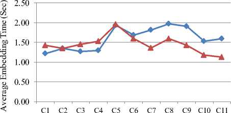
Poonkuntran and Rajesh watermarking scheme, and our proposed watermarking scheme are used in turn to embed a watermark of fixed size into each of the 1050 samples in our dataset. The embedding time for each sample is calculated and recorded. Finally, we calculated the average embedding time for each category in our dataset. Fig. 7 shows the obtained results of this experiment.
Category ID ф Poonkuntran and Rajesh scheme —*— Proposed scheme
Figure 7: Comparing the embedding time of Poonkuntran and Rajesh watermarking scheme with that of our proposed scheme.
As seen in Fig. 7, at most of sample categories our proposed CA algorithm is superior to or at least the same as Poonkuntran and Rajesh algorithm regarding the average embedding time despite of having a small difference. At the other categories, namely, C1, C3, and C4, the average embedding time of our proposed algorithm exceeds that of their algorithm by no more than 0.25 second. Finally, the recorded average embedding time for all samples using our proposed scheme is 1.45 seconds while using Poonkuntran and Rajesh scheme is 1.60 seconds.
During each watermark embedding process, both schemes visit all the locations of the host image; forming pairs of pixels. At each watermark bit embedding, the expandability of the difference of the corresponding pixels pair is checked. If it is found expandable, the bit is embedded by replacing the pixels of that pair. Otherwise, both the bit and its corresponding pixels pair are ignored, and both schemes move to the next bit and pixels pair. Thus, at each watermark bit embedding, the corresponding image location is accessed two times. The first time is merely for reading the pixels pair, the second is for writing the new pixels pair. Because Poonkuntran and Rajesh watermarking scheme forms pixels pairs among two different color plans of the host image while our proposed watermarking scheme forms pairs using the neighboring pixels at the same color plan; our proposed algorithm is faster than Poonkuntran and Rajesh algorithm.
-
VI. conclusion
In this paper we proposed a content authentication watermarking scheme. The proposed scheme is a fragile and reversible watermarking scheme for tiny tamper detection of color images. It is a development of another technique proposed by Poonkuntran and Rajesh. Two drawbacks of their scheme are solved in our scheme.
The first drawback is regarding the lack of fragility of their scheme. Modifications in some specific locations in the watermarked image might not be detected using their scheme. We overcome this drawback by proposing an accumulative watermark embedding process, which aims at spreading the watermark over whole image’s area. A wide and non-uniform spreading of the embedded watermark is accomplished in our proposed scheme, and hence, any modification in the watermarked image is necessarily sensed, even if it is very small.
The second drawback of Poonkuntran and Rajesh scheme is regarding the low quality of its generated watermarked images. Because embedding in their scheme is performed by replacing old pixel values with new distant values. We overcome this drawback by proposing a homogenous watermark embedding process, which aims at producing a high quality, undistorted, watermarked image. It embeds the watermark by expanding the differences between the neighboring pixels at the same color plan, in a method called interplan difference expanding, which is performed based on the Integer Transform (IT).
Our proposed scheme is evaluated and compared with its counterpart. Tests are performed based on a dataset of 1050 samples from eleven categories. Results are averaged over all the dataset samples. Our proposed scheme showed a noticeable superiority over its counterpart in terms of capacity, quality, robustness, fragility, and time.
Finally, the proposed scheme work in the spatial domain, which requires a lower computational cost than that required in transform domain based schemes.
References An Improved Watermarking Scheme for Tiny Tamper Detection of Color Images
- L. Fan, T. Gao, Q. Yang and Y. Cao, "A copyright-protection watermark mechanism based on generalized brain-state-in-a-box neural network and error diffusion halftoning," IEEE Int. Conf. on Multimedia and Expo, (ICME), China, 2011, pp. 1-6.
- C. Xiaoling, and Z. Huimin "A Novel Video Content Authentication Algorithm Combined Semi-fragile Watermarking with Compressive Sensing," 2nd Int. Conf. on Intelligent System Design and Engineering Application, (ISDEA), 2012, pp. 134-137.
- Y. Hu, H. Lee, and H. Zeng, "Curve Watermarking Technique for Fingerprinting Digital Maps," 8th Int. Conf. on Intelligent Information Hiding and Multimedia Signal Processing, (IIHMSP), 2008, pp. 223-226.
- A. Giakoumaki, K. Perakis, A. Tagaris, D. Koutsouris, "Digital Watermarking in Telemedicine Applications - Towards Enhanced Data Security and Accessibility," Proc. of the 28th IEEE Annual Int. Conf. on Engineering in Medicine and Biology Society, (EMBS), New York City, USA, 2006, pp. 6328 – 6331.
- M. Prasad and Sh. Koliwad "A Comprehensive Survey of Contemporary Researches in Watermarking for Copyright Protection of Digital Images," International Journal of Computer Science and Network Security, vol. 9, no. 4, pp. 91-107, Apr. 2009.
- F. H. Wang, J. S. Pan, and L. C. Jain, "Digital Watermarking Techniques," in Innovations in Digital Watermarking Techniques, Berlin, Heidelberg: Springer-Verlag,2009, pp. 11-26.
- B. Harjito, S. Han, V. Potdar, E. Chang, M. Xie, "Secure Communication in Wireless Multimedia Sensor Networks using Watermarking," 4th IEEE Int. Conf. on Digital Ecosystems and Technologies, (DEST), 2010, pp. 640-645.
- E. Bollain-y-Goytia, M. Nakano-Miyatake and H. Pérez-Meana, "Authentication of Identification Card Using Watermarking," 48th Midwest Symposium on Circuits and Systems, 2005, pp. 1422 - 1425.
- S. Poonkuntran and R. S. Rajesh, "A Messy Watermarking for Medical Image Authentication," in Proc. of 2011 Int. Conf. Communications and Signal Processing, Kerala, pp. 418-422.
- S. Mohanty, "Digital Watermarking: A Tutorial Review ," Master Project Report, Dept. of Electrical Engineering, India, Institute of Science, DANGALORE, India, 1999.
- M. Jiansheng, L. Sukang, and T. Xiaomei, "A Digital Watermarking Algorithm Based On DCT and DWT," Proc. of the Int. Symposium on Web Information Systems and Applications, (WISA'09), Nanchang, P. R. China, 2009, pp. 104-107.
- A. Zeki and A. Manaf, "A novel digital watermarking technique based on ISB (Intermediate Significant Bit)," World Academy of Science, Engineering and Technology, 50. 2009, pp. 989-996.
- Y. Hua, B. Wu, and G. Wu, "A color image fragile watermarking algorithm based on DWT-DCT," in Proc. 2010 Chinese Control and Decision Conf., (CCDC), Xuzhou, 2010, pp. 2840-2845.
- S. C. Liew and J. M. Zain, "Reversible Medical Image Watermarking For Tamper Detection And Recovery," in Proc. Int. Conf. Computer Science and Information Technology, (ICCSIT),Chengdu, 2010, pp. 417-420.
- J. Tian, "Reversible Watermarking Using a Difference Expansion," IEEE Trans. Circuits Syst. for Video Technology Video Technol., vol. 13, no. 8, pp. 890-896, 2003.
- R. Ni, Q. Ruan, and Y. Zhao, "Pinpoint authentication watermarking based on a chaotic system," Forensic Science International Journal, vol. 179, no. 1, pp. 54-62, 2008.
- Jia Li and James Z. Wang, "Real-time Computerized Annotation of Pictures," IEEE Transactions on Pattern Analysis and Machine Intelligence, vol. 30, no. 6, pp. 985-1002, 2008.
- http://wang.ist.psu.edu/docs/related.shtml/, James Z. Wang Research Group, Accessed 5 Jan 2013.
- http://www.sciencephoto.com/, online image library, Accessed 5 Jan 2013.
- Mrdjenovic and Ljiljana "Digital watermarking in the generalized discrete cosine transform domain," M.S. thesis, Dept. Comput. Sci., York University, Toronto, Ontario, Jan. 2010.
