An Ingenious Wireless Home Security System and Protocol based upon Multi-hop 802.15.4 standard, Magnetic contact and PIR sensor

Author: Ulya Sabeel, Nidhi Chandra, Shivraj Dagadi
Journal: International Journal of Modern Education and Computer Science (IJMECS) @ijmecs
Article in issue: 7 vol.5, 2013.
Free access
Security is the major part of home automation systems for the people. With the development of network and automatic control technology, a home security monitoring and alarming system becomes more and more practicable today. In this paper we have proposed simple, low cost, low power consumption and a novel method for implementing the home security using Zigbee (802.15.4) standard and also a security protocol for detecting and localizing identity based attacks in the system. We have named our scheme as Wireless Home Security System (WHSS) and protocol as Wireless Home Security Protocol (WHSP). It consists of many sensor nodes deployed in the rooms as well as the doors/ windows of the house together with the zigbee modules which act as end devices that monitor continuously and send the security status of each room to the coordinator node connected to a PC which acts as the master. The communication in this case is multi-hop which provides unlimited range. Here we have used the XBEE Pro series1 (XBP24-AWI-001) radios for RF communication, DYP-ME003 PIR sensor, and Contact Door / window sensor based on magnetic reed switch (ORD221).The hardware implementation has been tested for validation successfully. The software has been implemented using C#. Also the performance of our proposed security protocol has been analysed using NS2 and is found to be satisfactory.
Wireless sensor networks, Zigbee, PIR sensor, Reed switch, Multi-Hop, RF communication
Short address: https://sciup.org/15014567
IDR: 15014567
Text of the scientific article An Ingenious Wireless Home Security System and Protocol based upon Multi-hop 802.15.4 standard, Magnetic contact and PIR sensor
Home security is one of the essential requirements for everyone nowadays due to the high rate of crimes. People are intended to take certain measures to detect and prevent this intrusion. A smart home based upon WSN deploys sensors around some places in the house to provide precise monitoring. This provides a cost effective solution to detect intrusion and prevent burglary at the owner’s home in his absence. This provides a convenient and safe environment for the owner. In addition, the implementation of wired system is error prone, costly, time consuming and uses more power. These shortcomings may be prevented by replacing the traditional wired networks by WSN technology.
In this paper we have proposed a Zigbee, Passive Infrared Sensor and Magnetic contact based Wireless Home Security System (WHSS). ZigBee is a low cost, low power wireless technology that operates on the IEEE 802.15.4 physical radio specification and uses unlicensed bands including 2.4 GHz, 900 MHz and 868 MHz [12]. We have preferred to use Zigbee (802.15.4) for our scheme owing to the numerous advantages associated with it as compared to the traditional schemes that use the wireless networks like Wi-Fi (802.11), Bluetooth (802.15.1). Although, Wi-Fi provides higher throughput, yet it can’t be used due to the higher power consumption as compared to Zigbee. Bluetooth has high data rate, thus a higher power consumption and can handle only limited number of nodes as compared to Zigbee which can handle a large number of nodes in the mesh topology. Thus, Zigbee is the best solution for battery longevity and can be used effectively for wireless communication in case of highly sensitive systems like Home security. Here we use the XBEE Pro series1 radios that follow the Zigbee standard.
Passive Infrared (PIR) sensor has been used to sense human motion by detecting the IR radiations emitted from human body. The door/ window sensor is basically a magnetic contact reed switch. The switch remains open when no magnetic field is present and vice versa. The details of implementation have been discussed elaborately in the further sections of the paper.
In addition to this, we have proposed a simple, reliable, non-cryptographic and energy efficient security protocol that we named as Wireless Home Security Protocol (WHSP) and algorithm for detecting and localizing identity based attacks like spoofing effectively in the present scenario.
The rest of the paper has been divided as follows: Section I consist of the related work; section II consists of the Proposed system, section III consists of detailed hardware design, section IV provides the system implementation, section V consists of the Wireless Home security protocol, and finally we come to our conclusion in section VI.
-
II. RELATED WORK
The design for an intelligent Home Security System is one of the most recent trends nowadays. Many techniques have been given in the literature. Many techniques like Bluetooth, GSM (Global System for Mobile communication), GPRS (General Packet Radio Service), FPGA (Field Programmable Gate Arrays), MCU (Micro Controller Unit), and Cloud Computing have been used.
A Java based home automation scheme has been introduced with an embedded board connected to all devices and integrated with PC based web server in [1]. A mobile based home automation system that uses Java, Internet and GPRS for connectivity has been introduced in [9].It uses many wired sensors that are costly and difficult to install. A Bluetooth based home automation system with a primary controller and a number of Bluetooth sub-controller has been introduced in [2]. In [3] the authors have introduced a phone based remote controller for home and office automation. An Open Service Gateway Initiative has been proposed in [4] to access home automation systems for administration services. In [5] an MCU- based home wireless control center has been proposed. This also consists of one sensor node, GSM Module and mobile phone. A GSM based remote sensing and control system using FPGA has been introduced in [6]. A GSM based home automation system with Internet and speech recognition and home gateway as internet via PC has been introduced in [7]. An internet based intelligent home power management system; using cloud home gateway has been introduced in [8]. In [10] a Programmable System on Chip (PSoC) microcontroller, with Zigbee for RF communication has been used with no camera and webservers. The analysis of the essential schemes for remote monitoring and control of home appliances and security has been introduced in [11].
Most of these existing systems employ complex and have expensive architecture. They are difficult to install due to the physical wiring used. They use a single method for monitoring and control. Finally these existing approaches have not taken into consideration the security (authenticity) aspect of the network or node. On the other hand, our proposed system takes into account all these conditions. It employs the use of low cost, low power Zigbee modules for RF communication instead of Bluetooth and Wi-Fi that have higher power consumption. The use of Zigbee provides a scalable architecture to the system. Zigbee employs the use of multi-hop communication for data transfer and thus has an unlimited range as compared to traditional systems used. Moreover, no complex components have been incorporated thus making our system cheaper than the other systems. Also, taking the security and authenticity of the nodes (network as a whole) into consideration, we have proposed an algorithm for detecting and localizing the identity based attacks like spoofing thus preventing the system from large scale attacks like Denial of Service and Resource Depletion attacks. These features have not been incorporated in any other home security systems till now. Thus, all these features make our system better than others.
-
III. PROPOSED SYSTEM
This consists of two sections that explain the system architecture and system operation respectively.
-
A) System Architecture
The architectural diagram for WHSS is given in proposed system uses 5-8 sensor nodes and XBEE pro series1 radios (for RF communication) fixed on the doors and windows of the house so as to prevent the intruder from entering the house. For testing purpose, we configured three of the XBEEs as end devices, one as a router and the other one as a coordinator, which is connected to the PC side. The software that we have used for configuration of XBEE radios is X-CTU. It was downloaded from [15]. The end devices and the sensors are fixed on the doors/ windows of different rooms of a house e.g. Bedroom, Kitchen, and Hall. They communicate wirelessly with the router that may be placed somewhere in the house where it is in range with all the other XBEES. This router routes the information to the coordinator XBEE that is connected to a PC, which displays the information, generates an alarm using a buzzer and if GSM module is embedded (not shown in the figure); a message may be send to the owner.
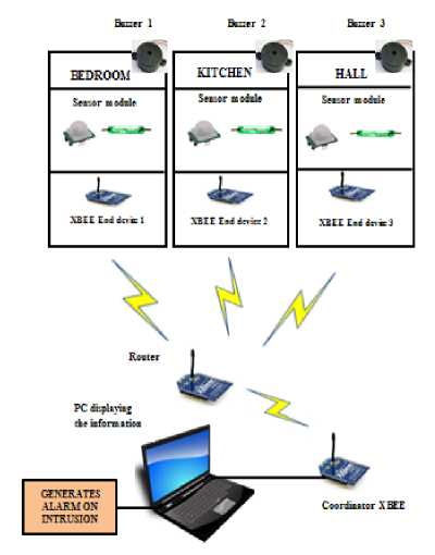
Figure 1: Architecture diagram
-
B) System Operation
-
2.First we configure all end device XBEEs.
The system operates as shown in the flow chart in Fig.
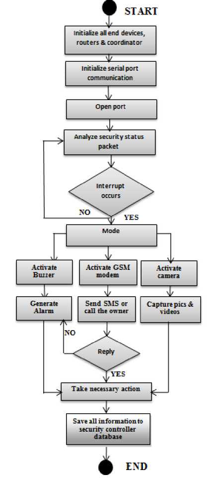
Figure 2: Flow chart for system operation
Then mount them in proper positions in the house along with the sensor nodes (PIR and Magnetic Contact sensors).Then, initialize the coordinator XBEE connected to PC. Set all the initial values for the coordinator like COM Port, Baud Rate, Data bits, Stop bits and Parity. Then, Open the COM port using our Application Program. Analyse the security status packets received from the end devices continuously. If interrupt occurs (i.e., security status= 1), then generate the buzzer alarm, activate the camera and start capturing the pictures of the place of intrusion, activate the GSM modem and send SMS Alert to the owner’s mobile and local police station. Transmit the photos captured to the security controller using XBEE and save all this data. This technique effectively monitors the house and localizes as well as detects intrusion thus preventing the house from burglary.
-
IV. DETAILED HARDWARE DESIGN
In this section we have explained our detailed hardware design. Our proposed scheme consists of three components. They are given as under:
-
1. RF communication system using XBEE Pro series1 radios
-
2. The sensing system (Magnetic contact sensors, PIR sensor)
-
3. The Surveyance System (Remote PC, buzzer and cameras)
These components have been discussed in detail in the further sections.
-
A) RF Communication System using XBEE Pro Series1
This consists of the XBEE Pro series1 (XBP24-AWI-001) radios for RF communication. They are used for point to multipoint communication. They are used specifically because of their advantages such as low cost and low power consumption, high throughput and low latency. The XBEE Pro series1 radios have been used because they provide an extended range of communication and are modified versions of simple XBEE radios. The specifications are given in table 1.The schematic diagram for XBEE Pro series1 is given below in fig 3.
T ABLE 1 S PECIFICATIONS O F X BEE P RO S ERIES 1
R ADIO
|
PARAMETERS |
VALUES |
|
Indoor range |
300ft (90m) |
|
Outdoor range |
Up to 1 mile (1600m) |
|
Transmit power |
63mW |
|
RF data rate |
250,000bps |
|
Supply voltage |
2.8-3.4 V |
|
Transmit current |
250 mA at 3.3V |
|
Operating frequency |
ISM 2.4GHz |
|
No. of channels |
12 direct sequence channels |
|
Addressing options |
PAN ID, channel and addresses |
The XBEE Pro Series1 consists of 20 pins. These are configured accordingly to make them as end devices, router and coordinator. The DIO pins are used for communication without any change in the hardware and are configured using X-CTU software. The configuration settings for base (coordinator) and end device are given in table 2.

Figure 3: Schematic diagram for XBEE Pro Series
T ABLE 2 C ONFIGURATION S ETTINGS F OR E ND D EVICE A ND C OORDINATOR
|
End Device |
Coordinator |
|
CH=C |
CH=C |
|
ID=0x1 |
ID=0x1 |
|
DL=0x1234 |
DL=0x4567 |
|
MY=0x5678 |
MY=0x1234 |
|
CE=0x0 |
CE=0x1 |
|
SD=0x4 |
SD=0x4 |
|
PR=0x0 |
PR=0xFF |
|
D0=0x3 |
D0=0x4 |
|
D1,D2,D3=0x3 |
D1=0x4 |
|
IC=0x18 |
IU=0x1 |
|
IU=0x1 |
IT=0x1 |
|
IT=0x1 |
IR=0xFF, IA=0x4567 (or FFFF) |
|
IR=0xFF |
T3,T4=0x64 |
These settings will set the End device once every 255ms. Before sending it back to the coordinator, the end device will buffer 1 sample packet. The coordinator will receive a 14 byte packet (2 bytes data and 12 bytes framing) and same can be seen in the coordinator as communication is configured to be both ways. The router is configured in the same way as the end device. Configuration settings for coordinator can be shown in fig. 4 and fig. 5 shows the structure of status packet sent from end device to coordinator.
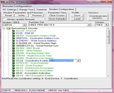
Figure 4: Configuration of XBEE as coordinator
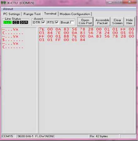
Figure 5: Structure of Status packet sent from end device to coordinator
-
B) The Sensing System for Wireless surveillance
The sensing system consists of the wireless sensor network (WSN) which is composed of many sensor nodes. These act as the end devices and one of them may act as a master (coordinator). This coordinator node is the one that controls the network. All the end devices send their information to the coordinator which takes a decision. As the communication is multi-hop, few nodes may act as routers for just routing the information hop by hop to the destination.
In our proposed scheme, two types of sensors have been used.
-
1) The Passive Infrared Sensor (PIR Sensor)
-
2) The Magnetic Contact Sensor (Reed switch)
-
1) The Pyroelectric (Passive) Infrared Sensor
The Pyroelectric sensor develops an electrical signal when it detects a change in thermal radiation. The human body emits some radiation (heat) and whenever someone passes by the sensor, it detects some change in thermal radiations and confirms intrusion in the house. The PIR sensor we have used is DYP-ME003. The specifications for the sensor have been given in table 3.
The sensor is a motion detector and is split into two halves which are wired up such that they cancel out each other. If the radiation received by one half is high/ low as that of the other, there is a positive/ negative differential change between the two halves and the output can be seen as high/ low [13]. A number of resistors, capacitors and a micro power IC BISS001 are used with this sensor. The IC is used for taking the output and processing it. PIR sensor uses the Fresnel lens (compact lens) that captures light obliquely, providing a greater range of Infrared rays to the sensor. The pin diagram for PIR sensor is given in Fig. 6.
T ABLE 3
S PECIFICATIONS O F D YP -M E 003 P IR S ENSOR
|
Parameters |
Values |
|
Operating voltage |
4.5V to 20V DC |
|
Voltage level output |
High 3.3V, low 0V |
|
Delay time |
5s-200s (adjustable) |
|
Blocking time |
2.5s |
|
Max detection angle |
110 degrees solid angle |
|
Max detection distance |
Adjustable between 3m and 7m |
|
Trigger |
L can’t be repeated, H can be repeated |
|
Quiescent Current |
<50uA |
|
Operating temperature |
-15 to +70 degrees |
|
Lens size |
Default diameter: 23mm |
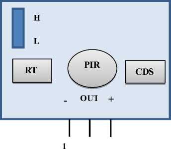
Figure 6: Pin diagram for PIR sensor
To provide a broader range, it is suspended at a depth of 2 feet from the ceiling of the lobby, dining areas, etc. so as to get the full coverage of the area. Many such sensors can be mounted to monitor the whole area effectively.
The sensor is connected to pin D0 of XBEE Pro series1 (end device) which is configured as the input pin (D0= 0x3). The PIR sensor continuously monitors the area and sends regular security status reports using end device XBEE radio to the coordinator (XBEE connected to the PC). Whenever any human motion is detected at the specific location in the house, the sensor senses it and the security status set to 1 which represents intrusion. This information is passed to the coordinator node which detects intrusion and generates an alarm using the buzzer which is implemented using NPN BC547 transistor with 1K resistor. An LED may be used to provide indications for the PIR sensor outputs. The coordinator XBEE is connected to the PC using USB Serial Port. This informs the owner of the house that some intrusion occurred in the specific room of his house where the sensor node has been placed. Thus, we are able to locate the exact position of intruder. Also, a text message may be send to the owner’s mobile and local police station using the GSM Module. The diagrammatic representation of PIR sensor node is given in Fig.7.
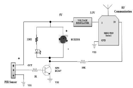
Figure 7: PIR sensor node (end device)
-
2) The Magnetic Contact Sensor (Reed switch)
Besides using the PIR sensor, we have also used the magnetic contact door/ window sensors. A magnetic contact sensor consists of a very inexpensive reed switch. A reed switch is an electro mechanical device which has two inner contacts called reeds made up of ferromagnetic material and encased in a glass/ plastic shell. The length of a reed switch is around 2 inches-0.025 inches [14]. They usually operate at low voltage loads.
The working of the reed switch may be explained as follows. The two inner reeds act as magnetic flux conductors when exposed to external magnetic field like horse-shoe magnet or a strong button magnet (used in our case). When a magnet is brought near the switch, the two contacts are ‘closed’ because the magnetic force exceeds the spring force on the reeds, which generates opposite polarities on the two reeds. Thus, the current will flow through the switch. On the other hand, when the magnet is moved away from the switch, the reeds are open’ so that the magnetic force between the reeds is less than the spring force they experience and no current flows through the switch. The operation of a basic reed switch is shown in the Fig.8. The reed switch that we have used is ORD221 which operates at the loads less than 100V. The specifications are given in table 4.
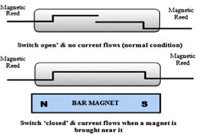
Figure 8: Operation of a basic reed switch
T ABLE 4
S PECIFICATIONS O F O RD 221 R EED S WITCH
|
Parameters |
Values |
|
Max switching voltage |
100V DC/AC |
|
Max switching current |
0.3A |
|
Max carrying current |
1.0A |
|
Drop out value |
5min AT |
|
Pull in value |
10-30 AT |
|
Length |
13mm |
|
Operating time |
Max 0.4ms |
|
Bouncing time |
Max 0.5ms |
|
Releasing time |
Max 0.05ms |
|
Max operating frequency |
500Hz |
In our proposed system, we have used 5 reed switches for testing purpose. They were mounted on 4 solid windows and one solid door of the room. The operating gap for the reed switch to function when a magnet is brought near to it is around 15mm.The magnetic contact sensor is connected to pin D1 (pin number 19) of XBEE Pro series1 (end device) which is configured as the input pin (D1= 0x3). The diagrammatic representation of Magnetic Contact sensor node is given in Fig.9.
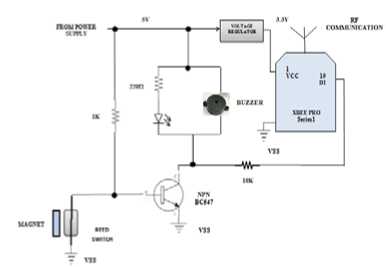
Figure 9: Diagram for Magnetic Contact Sensor node
This is fitted at the opening edge, near the top of the door/ window such that it may prevent physical damage or damage due to moisture, etc. The magnet is fitted to the moving part of the door/ window while the reed switch is fitted to the static door/ window frame. The working procedure is same as that of the PIR sensor The magnetic sensor continuously monitors the door/ window on which it has been mounted and sends regular security status reports using XBEE radio (end device), to the coordinator (XBEE connected to the PC). Whenever the door/ window of a specific room in the house are opened, the sensor senses it and the security status set to 1 which represents intrusion. This information is passed to the coordinator node which detects intrusion and generates an alarm using the buzzer which is implemented using NPN BC547 transistor with 1K resistor. An LED may be used to provide indications for the reed switch outputs. The coordinator XBEE is connected to the PC using USB Serial Port. This informs the owner of the house that the door/ window of a specific room have been opened. Thus, we are able to locate the exact position of intruder. Also, a text message may be send to the owner’s mobile and local police station using the GSM Module. The pictures and videos of the intruder may be captured using the cameras fitted in various rooms of the house.
-
C) The Surveyance System (Remote PC, buzzer and cameras)
The Surveyance system is basically the event monitoring and capturing system. Our Surveyance system consists of a remote PC that is connected to a coordinator XBEE via USB Serial cable. Each sensor node (PIR and Magnetic Contact sensor) sends the regular security status reports to the coordinator which analyses them carefully. The GSM Modem as well as the surveillance camera is connected to the PC via USB. It has a database that contains the record of all the information captured. We have written the application program using C#. Whenever an intrusion is detected by the sensors, the security status is set to 1(no intrusion security status is 0) and the data is send to the coordinator which confirms the intrusion, generates an alarm using the buzzer connected to the end device from where the intrusion report has been received and sends SMS to the owner and local police station via GSM modem. Thus, it helps in detecting as well as localizing the intruder. Also, the camera is used to capture all the pictures and videos during intrusion. This can be shown in fig. 10.
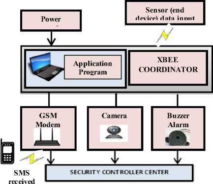
Figure.10: Sensor node communicating with Surveyance Management System
-
V. SYSTEM IMPLEMENTATION
This section consists of the detailed software and hardware implementation.
-
A) Software implementation
The PC contains our Application program that has been written in C#. All the communication, monitoring and capturing of events can be done using this program.
This program is based upon the serial communication and behaves in the same way as the XCTU software for XBEE configuration.The screenshots for the software implementation have been given in fig.11 and fig. 12.These figures show the security status of each room of the house under consideration. The sensors send regular security status reports to the coordinator XBEE connected to the PC. The PC displays the result using our application program. Fig.11 illustrates the security status of all the rooms where the sensors were placed. The color ‘Green’ indicates ‘safe’ condition and no intrusion in the house. In Fig.12, intrusion has been detected by the sensors in two areas of the house (bedroom and lobby) and status is send to coordinator XBEE which is depicted using our application program and an alarm is generated and SMS may be send to the owner using GSM modem.
with the coordinator XBEE connected to a PC.
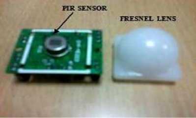
Figure 13: Picture for PIR sensor
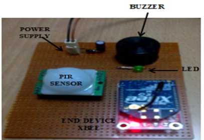
Figure 14: Picture depicting the end device PIR sensor module
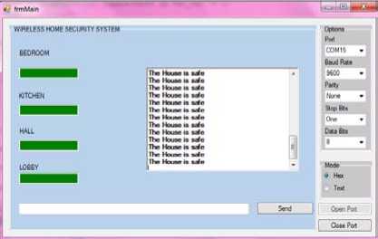
Figure 11: Security status of all the rooms in the house depicting safe condition using our application program
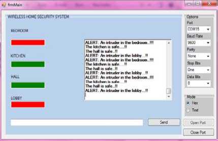
Figure 12: Intrusion detected in bedroom and lobby indicated by red color
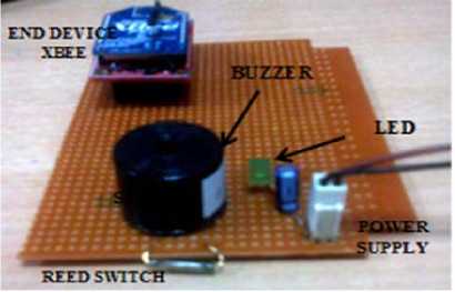
Figure 15: Picture depicting the end device Magnetic Door/Window sensor module
-
B) Hardware Implementation
The hardware has been implemented successfully. The 3 basic hardware components (already explained in detail in the above sections) that we have used are: XBEE Pro series 1 (XBP24-AWI-001 ) radios for RF communication, Pyroelectric (Passive) Infrared sensor (DYP-ME003) and Magnetic contact sensor using reed switch (ORD221).The implementation can be shown in the pictures given below. These pictures given in fig. 1319 depict the individual sensor nodes (PIR and Magnetic contact reed switch) and also how they communicate
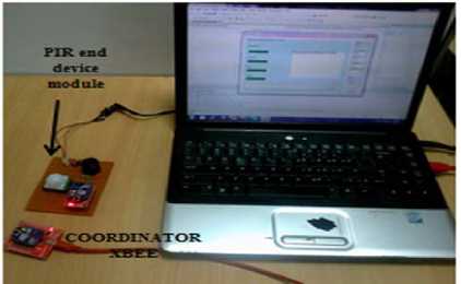
Figure 16: PIR end device communicating with coordinator XBEE
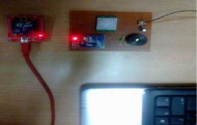
Figure 17: A closer look on PIR end device communicating with coordinator
Service user:
END DEVICE
End Node requests base station to enter into the network
Confirm and enter into the network
Service provider N layer
Service User:
BASE STATION/
CLUSTER HEAD
Accept request if node key not replicated else reject
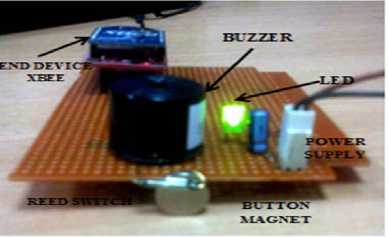
Figure 18: Reed switch is opened when a magnet is brought near
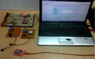
Figure 19: Picture depicting Complete System Implementation
-
VI. W IRELESS H OME S ECURITY P ROTOCOL
The Wireless Home security System demands high security and imposes many constraints on the authenticity of sensor nodes, the information being transmitted and energy consumed. An attacker may claim the identity of a legitimate sensor node (PIR sensor/ Magnetic Contact sensor) and replays false information into the network. This creates problems if done on a large scale rendering all the services to legitimate nodes useless. Such an attack is called Denial of Service. This may lead to the failed operation of the security system. Thus, it is very important to detect and localize these spoofing attackers to prevent this wireless home security system to come to a halt. In order to prevent this, we have proposed a protocol and algorithm given below to detect and localize such attacks. This protocol can be shown in fig.20 below.
Figure. 20.Wireless Home Security Protocol (WHSP) for node authentication
First a unique ID is generated for all the nodes in the network using MD5 Hash algorithm and HMAC. Each node in the network has a secret hash key associated with it. An adversary tries to replay some false information into the network by claiming to be a legitimate node. It sends the request to the coordinator node which verifies the hash key associated with the attacker node. If the hash key is found to be replicated, it detects the presence of spoofing attackers in the network. Then the attacker is identified and its exact position is located using Least Mean Square Error Method. The algorithm is given below.
ALGORITHM TO DETECT AND LOCALIZE
SPOOFING ATTACKS IN WHSS
STEPS:
Step 1 : Generate Unique ID for all nodes in the network using MD5 algorithm i.e. 128 bit Hash value
Step2 : For each node, generate the MAC value by combining the single random key ‘K’ and the message of length’ L’ using HMAC algorithm
HMACk (y) = f (K’ ⊕ opad||f (K’ ⊕ ipad||y)) T
Step 3: Define the cluster and the nodes in clusters
Step 4: Let Clusters in Network be ‘Cn’
Step 5: For (i=0; i<=Cn)
{
AttackerNode A=0;
Perform spoofing attack detection by checking the node key value in every cluster
A=A++;
//Node, which has replicated key value, is identified as attacker node
}
Step 5: Perform the detection in every cluster
Step 6: Identified number of attackers ‘A’
Step 7: Localize the Attacker by applying “Least mean square error method” to find value of position coordinates (Xo, Yo) of the node.
References An Ingenious Wireless Home Security System and Protocol based upon Multi-hop 802.15.4 standard, Magnetic contact and PIR sensor
- A. R. Al-Ali and M. Al-Rousan, "Java-based home automation system",IEEE Transactions on Consumer Electronics, vol. 50, no. 2, pp. 498-504, 2004
- N. Sriskanthan, F. Tan and A. Karande, "Bluetooth based home automation system", Microprocessors and Microsystems, Vol. 26, no. 6, pp. 281-289, 2002
- H. Ardam and I. Coskun, "A remote controller for home and office appliances by telephone", IEEE Transactions on Consumer Electronics, vol. 44, no. 4, pp. 1291-1297, 1998
- S. Ok and H. Park, "Implementation of initial provisioning function for home gateway based on open service gateway initiative platform", The 8th International Conference on Advanced Communication Technology, pp. 1517-1520, 2006
- D. Yoon, D. Bae, H. Ko and H. Kim, "Implementation of Home Gateway and GUI for Control the Home Appliance", The 9thInternational Conference on Advanced Communication Technology, pp.1583-1586, 2007.
- Huiping Huang, Shide Xiao, Xiangyin Meng, Ying Xiong,” A Remote Home Security System Based on Wireless Sensor Network and GSM Technology”, 2010 Second International Conference on Networks Security, Wireless Communications and Trusted Computing
- Wael M EI-Medany, Mahmoud R EI-Sabry. "GSM-Based Remote Sensing and Control System using FPGA" Proceedings of the International Conference on Computer and Communication Engineering 2008(ICCCE08)
- Baris Yuksekkaya, A. Alper Kayalar, M. Bilgehan Tosun, M. Kaan Ozcan, and Ali Ziya Alkar "A GSM, Internet and Speech Controlled Wireless Interactive Home Automation System" IEEE Transactions on Consumer Electronics, Vol.52 No. 3, pp: 837-843, 2006.
- M. Van Der Werff, X. Gui, and W.L. Xu. "A Mobile-Based Home Automation System" 2nd International conference on mobile technology, Applications and systems.pp 1-5, 2005
- Yanbo Zhao and Zhaohui Ye “A Low Cost GSM/GPRS Based Wireless Home Security System”, IEEE Trans. On Consumer Electronics, Vol. 54, No. 2, pp. 567-572, May 2008.
- K. Balasubramanian and A. Cellatoglu ”Analysis of Remote Control Techniques Employed in Home Automation and Security Systems”, IEEE Transactions on Consumer Electronics, Vol. 55, No. 3, pp. 1401-1407, Aug. 2009.
- http://www.digi.com/technology/rf-articles/wireless-zigbee
- http://www.ladyada.net/learn/sensors/pir.html
- http://www.reed-switch-info.com
- http://www.digi.com
