Analysis and optimization of the flow path within the protonic ceramic fuel cell stack

Author: Chen R., Efimov A.
Journal: Бюллетень науки и практики @bulletennauki
Section: Технические науки
Article in issue: 6 т.10, 2024.
Free access
With the development of human society, the demand for energy is increasing, and energy, an essential global necessity, is decreasing significantly and is in danger of being depleted. Fuel cell is the fourth power generation facility after hydroelectric, thermal and nuclear power. Fuel cell flow channel is an important part of fuel cell, which has the functions of transferring reaction gas, discharging products and excess unreacted gas, and balancing fuel cell temperature. This thesis focuses on the model design and optimization of a 10-layer flat-plate proton ceramic fuel cell (PCFC) reactor. First, we design a 10-layer flat-plate PCFC reactor model structure, then we simulate the reactor using Fluent, analyze the multi-field coupling operating characteristics inside the target reactor, optimize the reactor based on the results, and finally, we analyze and discuss the optimization results.
Proton ceramic fuel cell, flow path structure design and optimization, 3d large scale multi-physics simulation
Short address: https://sciup.org/14130492
IDR: 14130492 | UDC: 621.352.6 | DOI: 10.33619/2414-2948/103/39
Анализ и оптимизация пути потока в стеке протонного керамического топливного элемента
С развитием человеческого общества потребность в энергии растет, а запасы энергии, являющейся важнейшей мировой необходимостью, значительно сокращаются и находятся под угрозой истощения. Топливный элемент - это четвертый объект генерации энергии после гидроэлектростанции, тепловой и атомной энергетики. Проточный канал топливного элемента - важная часть топливного элемента, выполняющая функции перемещения реакционного газа, отвода продуктов и избыточного непрореагировавшего газа, а также выравнивания температуры топливного элемента. Данная диссертация посвящена разработке модели и оптимизации 10-слойного плоского реактора на протонно-керамическом топливном элементе (PCFC). Сначала мы разрабатываем модель 10-слойного плоского реактора PCFC, затем моделируем реактор с помощью Fluent, анализируем рабочие характеристики многополевой связи внутри целевого реактора, оптимизируем реактор на основе полученных результатов, и, наконец, анализируем и обсуждаем результаты оптимизации.
Text of the scientific article Analysis and optimization of the flow path within the protonic ceramic fuel cell stack
Бюллетень науки и практики / Bulletin of Science and Practice
UDC 621.352.6
Due to the development of industry in today's world, energy has reached a state of near depletion, fossil energy as a non-renewable energy source can not sustain human survival for a long time, excessive consumption and exploitation leads to energy near depletion. And the fossil fuel combustion products have a huge impact on the environment, triggering the greenhouse effect and other environmental degradation phenomena, causing harm to people's health, environmental issues and energy issues have become the primary problem we face, so there is a need for a high-efficiency, environmentally friendly and non-polluting energy. Fuel cell is a kind of chemical device that converts the chemical energy of fuel directly into electric energy, also known as electrochemical generator. Due to the high efficiency of fuel cells, no mechanical transmission noise, no harmful gas pollution and not subject to the limitations of the Carnot cycle effect, so the fuel cell is the most promising power generation technology at this stage, standing in the energy saving and environmental protection point of view [1].
There are generally five major types of fuel cells: alkaline fuel cells (AFC), proton exchange membrane fuel cells (PEMFC), phosphate fuel cells (PAFC), molten carbonate fuel cells (MCFC) and solid oxide fuel cells (SOFC). Solid oxide fuel cell (SOFC) is an electrochemical power generation device composed of dense oxide solid electrolyte and two porous electrodes (anode in contact with fuel and cathode in contact with oxygen), and its working principle is shown in Figure 1. Oxygen in the air reacts under the action of a catalyst to generate oxygen negative ions and migrates to the anode; at the anode, hydrogen in the fuel reacts to generate hydrogen ions and oxygen negative ions to produce water [2].
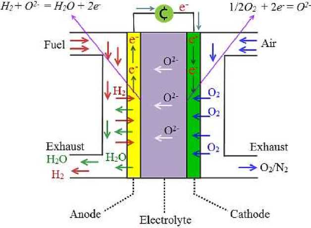
Figure 1. SOFC Operating Principle Diagram
As the anode loses electrons and the cathode gains electrons, a potential difference is formed between the two sides, and the external load is connected to form an electric current to achieve the purpose of converting chemical energy into electrical energy.
Proton conductive ceramics were discovered in Japan in 1981, and in recent years, they have attracted attention as an ultra-high efficiency device that surpasses SOFC [3].
Бюллетень науки и практики / Bulletin of Science and Practice Т. 10. №6. 2024
Proton ceramic fuel cell (PCFC) is actually one of SOFC, SOFC is divided into two types according to the charge carrier, the traditional SOFC is the oxygen ion conductor SOFC, and the other is the hydrogen ion conductor SOFC, which is also known as PCFC, PCFC has better performance and lower cost than SOFC, and the upper limit of fuel utilization can reach 93%. However, most of the previous studies on direct hydrocarbon fuel cells have focused on solid oxide fuel cells with oxygen ion-conducting electrolytes. Unlike SOFC, proton ceramic fuel cells utilize hydrogen ions, also known as protons, as conductors, and the generated water is produced at the air electrode [4].
Currently, fuel cell technology has been developed more mature, but there are still a variety of problems that we need to explore to solve, such as improving the working environment of the fuel cell, improving efficiency, reducing costs, improving safety and so on, which is what the study of the fuel cell has done. In this paper, we analyze and optimize the flow channel of proton ceramic fuel cell stack, and further explore the characteristic distribution of various physical quantities based on the indexes such as uniformity and temperature [5].
The essence of the electrochemical reaction occurring in a fuel cell is the combustion reaction of hydrogen, and the maximum heat energy that can be obtained from the fuel at atmospheric pressure depends on the reaction enthalpy.
General equation for the enthalpy of reaction (differential form):
dH = TdS + VdP(1)
By the first law of thermodynamics, at atmospheric pressure, there is:
dH = TdS = dU + dW(2)
Therefore, the reaction enthalpy Ah®xn of the reaction is:
Ah®xn = [mAh°f(M) + nAh0(N)] - [aAh^A) + bAh^B)(3)
Where Ah ® (M), Ah ® (N), Ah ® (A) and Ah ® (B) are the standard state enthalpies of generation of the corresponding substances, respectively [6].
Gibbs free energy in thermodynamics is a thermodynamic function introduced to judge the direction in which a process is proceeding. In layman's terms, the Gibbs free energy is the work potential of a system [7]. The differential form of Gibbs free energy equation is as follows:
dG = dH- TdS - SdT(4)
Isothermal conditions can be melted down to:
dG = dU- TdS - SdT + PdV + VdP(5)
-
1) The continuity equation:
^ + V-(pu) = 0
ot where, u – gas mixture velocity; ρ – gas mixture density.
-
2) Equation of conservation of momentum:
d(pu) . _ _ -(7)
-
—---+ V ■ (pu xu) = -Vp + V - t + SM
where, p – the relative pressure of a fluid; τ – stress tensor; S M – momentum source term.
-
3) Component conservation equations:
д(рсд dt
+ V-(pHci) = V-(pDfVci}+Si
where, c i – mass fraction of component i in the gas mixture; D i eff – effective mass diffusion coefficient for gas component i; S i – mass source term corresponding to gas component i.
Full model modeling and analysis of a 10-layer PCFC power stack
Firstly, we constructed a 10-layer flat PCFC stack based on the SOFC single-cell structure designed by Huang et al. in 2008, and the model of the stack can be divided into a half model and a full model, the half model is only the cathode or anode part of the stack, and the full model includes all the parts of the cathode and anode, and the full model is constructed in this paper (the main conduit, the anode, the cathode, the electrolyte, and the connection body) [8].
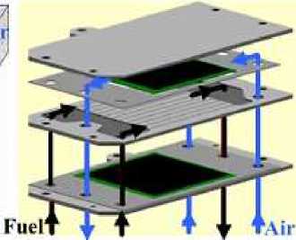
Figure 2. Flat plate SOFC fuel cell designed by Huang et al.
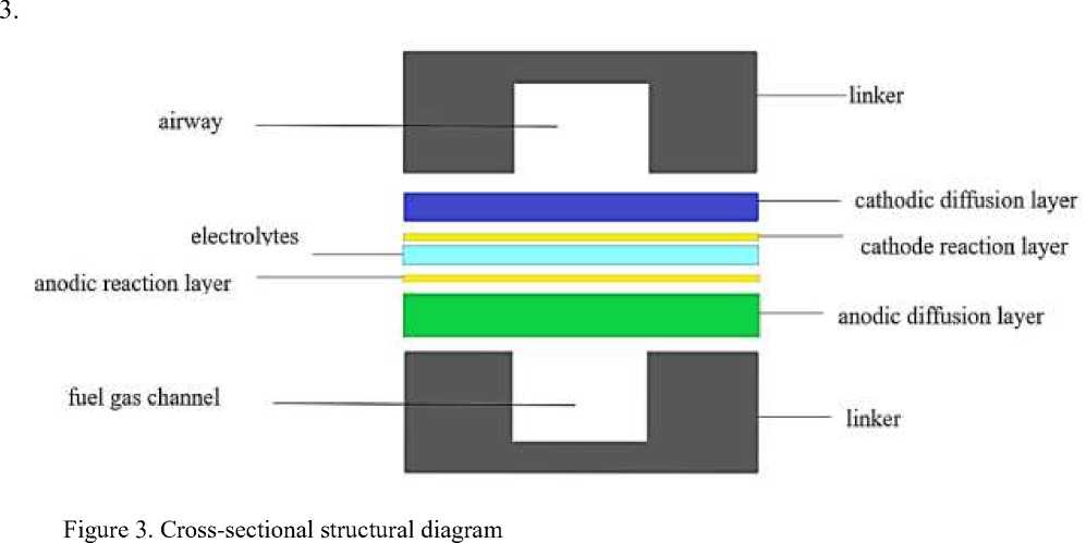
In this paper, the air and fuel of the designed stack are both two inlet and one outlet, and it is anode-supported type, with the cathode runner on the top of each layer of the cell, and the cathode diffusion layer, cathode reaction layer, electrolyte, anode reaction layer, anode diffusion layer, and the anode runner on the bottom in the middle portion from the top to the bottom, as shown in Figure
After the model is established, the model can be meshed directly by Gambit, and the selection of the mesh is very important, and the appropriate mesh is a necessary condition for the model to be solved accurately. In this paper, the structured mesh — submap mesh — is chosen for the regular parts of the model, which is more regular, and the cooper mesh is used for the irregular mesh [9]. Considering the computational time and computational complexity, the grid interval is 1 and all the grids are hexahedral grids.
After the delineation of the grid is completed, the cathode, anode diffusion layer, reaction layer and electrolyte in the electric reactor are named and defined, and the fuel, air inlet and outlet are named and defined. All these are for the preparation of computational solution in Fluent, the construction of the model and mesh division part of the end here, the model structure is shown in Figure 4.
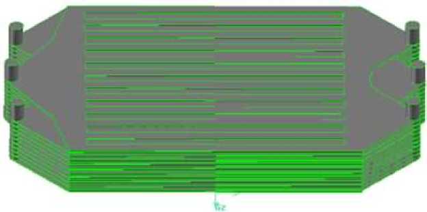
Figure 4. 10-layer PCFC fuel cell stack model
After meshing, we need to verify the quality of the mesh, because for different structures, the applicable mesh type is different, and the mesh quality affects whether the later solution calculation can be carried out smoothly and whether the calculation results are correct or not. If the model results change as the mesh density is adjusted, then the results are affected by the change in mesh density. When this happens, we need to encrypt the mesh or choose a more appropriate mesh type to ensure that the subsequent Fluent solver calculations run smoothly.
As shown in Figure 5, the quality of the grid of the power pile after the completion of the division, the entire model mesh is a hexahedral mesh, the number of 7713816, the mesh does not appear too large distortion, and when the mesh density changes, the calculation results are not very different, which means that the mesh quality meets the calculation requirements [10].
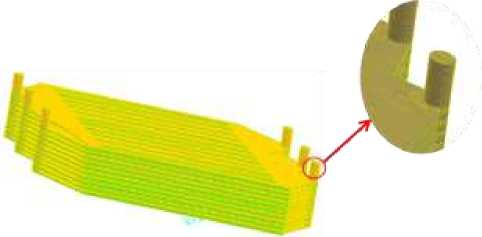
Figure 5. Mesh diagram of a 10-layer flat-plate PCFC stack model
Analysis and Optimization of Flat Plate PCFC Reactor Airway
For the stack constructed above, the air and fuel inlets and outlets are now changed to construct three kinds of stacks with different inlets and outlets, so that we now have four kinds of stacks with different inlets and outlets: 1) two inlets and one outlet for both air and fuel; 2) one inlet and two outlets for both air and fuel; 3) one inlet and two outlets for air and two inlets and one outlet for fuel; 4) one inlet and one outlet for air and one inlet and two outlets for fuel [7]. The runner components have been elaborated and pictured in the previous section (refer to Fig. 6) and the cathode part is above the anode i.e. the topmost runner is the air runner.
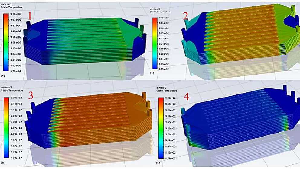
Figure 6. Comparison of the overall temperatures of the four electrostacks
The runner components have been described and pictured in the previous section (refer to Figure 3), and the cathode portion of the runner above the anode, i.e., the uppermost layer, is the air runner. Fig. 6 shows the overall macroscopic temperature comparison of the four power stacks, from left to right and from top to bottom for scenarios #1, #2, #3 and #4. It can be seen through the cloud diagram that, firstly, the fuel and air of the No.1 stack are two inlet and one outlet, and the temperature is higher in a small area at the end of the cathode air channel of the lower cell, while the temperature of the No.4 stack is high at the inlet of the cathode air channel of the lower cell, as well as there is a gradient of temperature decreasing from the bottom to the top of the fuel outlet, and such a small part of the area of high temperature and inhomogeneous should be avoided for stacks, while the temperature distribution of No. 2 and No .3 is high, and the temperature distribution of No. 2 and No. 3 is high. The temperature distribution of No. 2 and No. 3 is more uniform, the gas enters the gas channel and the reaction temperature rises, and the temperature distribution of each single cell is almost the same, and the high temperature area is the part of the gas channel; and due to the difference of the location of the water generation between PCFC and SOFC, the water generation in the PCFC reactor is in the cathode, so the temperature of the cathode is higher than that of the anode [11-13].
In general, the temperature distribution of No. 2 and No. 3 is better, but there are also subtle differences between the two, we can analyze more carefully by comparing the temperature distribution of the cell in which the single-layer.
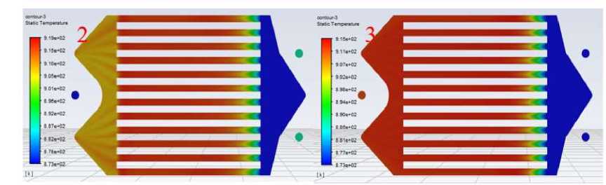
Figure 7. Comparison of cathode temperature distribution of single-layer cells of stacks 2 and 3
As shown in Figure 7 for the No. 2 and No. 3 stacks in the fifth layer of single-cell temperature distribution comparison, the temperature range of the two are roughly the same, the highest temperature occurs in the middle of the red area of the flow channel, the highest temperature of No. 2 is about 919.7 K, the highest temperature of No. 3 is about 915.8 K, the difference is relatively small, the two overall temperature difference between the battery is not big. However, the temperature of the left part of the single cell of No. 2, that is, the area where the gas passes through the gas channel and then converges towards the exit main, is lower compared to the gas channel part [14].
As mentioned in the previous section, the temperature difference will generate variable temperature stress, that is, thermal stress, the temperature difference in the gas channel of the single cell of the two power stacks is about the same, or to be precise, No. 3 is slightly smaller, and the temperature of the single cell of the No. 2 power stack will decrease after the gas flows out of the gas channel, which will generate a certain temperature difference. According to the above analysis, the No. 2 stack of single-cell gas channel inlet thermal stress will be slightly larger than the No. 3, and the 2 stack of single-cell gas channel outlet will also produce thermal stress due to the temperature difference. Thermal stress is due to the uneven heating of the components there is a temperature difference caused by the expansion or contraction of the various parts of the inconsistent, mutual constraints and internal stresses [15].
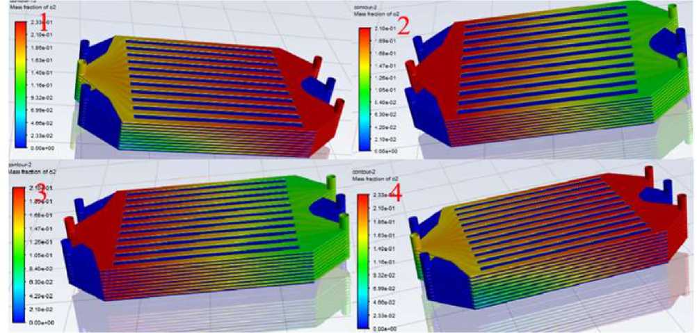
Figure 8. Comparison of Overall Oxygen Concentration Distribution of Four Types of Electric
Reactors
Then the structure of the No. 2 power reactor will be more affected, which is a threat to the stable operation of the power reactor, so in terms of temperature distribution or No. 3 power reactor is better!
The results of Fluent solving calculation show that the distribution of hydrogen concentration of the four schemes is more or less the same, which will not be elaborated here, while the distribution of oxygen concentration is very different. It can be clearly seen that the oxygen concentration of No. 1 and No. 4 from the top to the bottom of the oxygen concentration was a gradually decreasing gradient distribution, the first layer and the tenth layer of single-cell flow channel oxygen concentration difference is very large and leaning against the upper layer of the single-cell flow channel in the un-reacted oxygen is too much, this is the same as the optimization of the background of the previous situation, the heap in the operation of the heap to get the least flow of the single-cell still want to produce the same amount of current, the other single-cell will be get more airflow, then the air passing through the airway will be present with most of the oxygen not involved in the reaction. On the other hand, No. 2 and No. 3 are more evenly distributed, which ensures that each layer of single cells receives almost the same flow rate, thus avoiding the problem of unstable operation and performance degradation of the reactor due to non-uniformity of oxygen [16].
In summary, after the optimization of the three schemes, four kinds of power stacks are compared, the No. 3 power stack, that is, one inlet and two outlets of air, two inlets and one outlet of fuel is the optimal result.
Conclusions
In this paper, the modeling and multi-physics field coupling analysis of the power stack is carried out by using CFD software, and the simulation includes two parts. The first part is a comprehensive modeling analysis of the 10-layer flat plate PCFC stack with two inlets and one outlet for fuel and air; the second part is an optimization design based on the stack established in the first part, and the optimal scheme is selected from the four schemes for analysis and conclusion is summarized.
Through reading the literature, the import and export methods are changed, and a total of four import and export schemes of the stack are designed for the multi-physics field coupling analysis such as heat transfer, mass transfer, etc. After selecting the optimal results, the conclusions are mainly discussed with respect to the homogeneity of each physical quantity.
-
1) The inlet and outlet modes, positions and dimensions of the full model of the 10-layer PCFC stack have an impact on the stack performance;
-
2) According to the fluid concentration distribution diagram in the stack, we can find that the pressure drop in the air channel is much higher than that in the main channel, and the pressure drop in the main channel is kept lower, which has an improvement in the efficiency of the stack.
The standard mass flow rates obtained for the fuel and air channels are very uniform and close to the mean value, which avoids the inhomogeneity between the channels and affects the performance and normal operation of the reactor.
References Analysis and optimization of the flow path within the protonic ceramic fuel cell stack
- Dong, S. K., Jung, W. N., Rashid, K., & Kashimoto, A. (2016). Design and numerical analysis of a planar anode-supported SOFC stack. Renewable Energy, 94, 637-650. https://doi.org/10.1016/j.renene.2016.03.098
- Putilov, L. P., Demin, A. K., Tsidilkovski, V. I., & Tsiakaras, P. (2019). Theoretical modeling of the gas humidification effect on the characteristics of proton ceramic fuel cells. Applied energy, 242, 1448-1459. https://doi.org/10.1016/j.apenergy.2019.03.096
- Andújar, J. M., & Segura, F. (2009). Fuel cells: History and updating. A walk along two centuries. Renewable and sustainable energy reviews, 13(9), 2309-2322. https://doi.org/10.1016/j.rser.2009.03.015
- Hultman, M., & Yaras, A. (2012). The socio-technological history of hydrogen and fuel cells in Sweden 1978–2005; mapping the innovation trajectory. International journal of hydrogen energy, 37(17), 12043-12053. https://doi.org/10.1016/j.ijhydene.2012.06.023
- Li, Q., Chai, D., Wang, L., Zhang, X., & Li, G. (2021). Fine three-dimensional simulation of the heterogeneous anode of a solid oxide fuel cell with direct internal reforming. Chemical Engineering Science, 242, 116747. https://doi.org/10.1016/j.ces.2021.116747
- Huang, C. M., Shy, S. S., & Lee, C. H. (2008). On flow uniformity in various interconnects and its influence to cell performance of planar SOFC. Journal of Power Sources, 183(1), 205-213. https://doi.org/10.1016/j.jpowsour.2008.04.059
- Chen, G. (2003). Introduction to new materials. Science Press.
- Yan, Khua (2020). Prigotovlenie katodnykh materialov so smeshannymi provodnikami dlya protonnykh keramicheskikh toplivnykh elementov i issledovanie ikh elektrokhimicheskikh svoistv Tekhnologicheskii universitet Guanduna. (in Chinese).
- Ma, J. (2018). Modeling Analysis of Three-Dimensional Heat-Mass-Transfer- Electrochemical Multi-Field Coupling in Fuel Cell Electric Stack. Jiangsu University of Science and Technology. (in Chinese).
- Shi Sinsin i Yuan' Ichao (2020). Vliyanie konstruktsii reber na teploperedachu I soprotivlenie odnostoronnego teploobmennika s shchelevymi plastinami, Teplovaya energetika, 35 (6). (in Chinese).
- Cai, J. D, Li, J, Wang, G, & Fan, B. F. (2017). Simulation study of porous media for PECVD applications. Mechanical Design and Manufacturing, (5), 123-126.
- Zhang Shundong (2017). Research and optimization analysis of three-dimensional temperature field distribution of fuel cell electric stack. Jiangsu University of Science and Technology.
- Bi Wuxi (2009). Simulation and Optimization of Gas Channels in Flat Plate Solid Oxide Fuel Cells. University of Science and Technology of China.
- Cao, Jiafeng, Ji, Yuexia, & Shao, Zongping (2021). New understanding of proton conductor-based solid oxide fuel cells. Journal of Silicates, 49(01), 83-92.
- Chen, & Dai, Fen (2010). Microstructure theory and multi-scale multiphysics simulation of solid oxide fuel cell performance. University of Science and Technology of China.
- X., Xu. (2020). Preparation and theoretical study of key materials for proton conductor solid oxide fuel cells. Qingdao University.
