Analysis of QoS in Software Defined Wireless Network with Spanning Tree Protocol

Author: Rafid Mustafiz, Abu Sayem Mohammad Delowar Hossain, Nazrul Islam, Mohammad Motiur Rahman
Journal: International Journal of Computer Network and Information Security(IJCNIS) @ijcnis
Article in issue: 6 vol.9, 2017.
Free access
Software Defined Network (SDN) is more dynamic, manageable, adaptive and programmable network architecture. This architecture separates the control plane from the forwarding plane that enables the network to become directly programmable. The programmable features of SDN technology has dramatically improved network efficiency and simplify the network configuration and resource management. SDN supports Open-Flow technology as forwarding function and centralized control successfully. Wireless environment has recently added to the SDN infrastructure that has rapidly emerged with Open-Flow protocol. To achieve more deterministic network behaviors, QoS provisioning is a necessary consideration. In this paper, the Spanning Tree Protocol (STP) has applied on a SDWN and then analyzed the Quality of Service (QoS) using Mininet-Wifi. STP protocol is used to suppress the occurrence of broadcast streams and observe the performance of the QoS parameters. Various parameters that determine QoS, such as, bandwidth utilization, packet transmission rate, round trip time, maximum obtained throughput, packet loss ratio, delay time is analyzed for different base stations defined in the SDWN architecture.
QoS, Software Defined Wireless Networks, Mininet-Wifi, Spanning Tree Protocol
Short address: https://sciup.org/15011859
IDR: 15011859
Text of the scientific article Analysis of QoS in Software Defined Wireless Network with Spanning Tree Protocol
Published Online June 2017 in MECS
Software Defined Network (SDN) architecture provides a key technique to be used for the next generation network [1]. SDN promises to gain a significant improvements of the network performance by operating control plane and data plane separately based on Open-Flow (OF) protocol. Whereas in the traditional network system, packet forwarding and controlling performs in the same device that is not capable of adapting the growing challenge of network topology. To operate the emerging network requirements, SDN has developed a more flexible architecture by using OpenFlow protocol upon the traditional network infrastructure. Open-Flow controller and switch perform this function, providing with standard routing and forwarding [2]
technique. The data controlling actions are controlled by a software or hardware based centralized controller and data forwarding task has performed by a hardware core device [3]. This enables the control plane to be directly programmable which makes it suitable in the field of research. Data plane functionality contains features such as quality of service (QoS) [4]. The overall performance of a network topology depends mostly on the parameters of QoS. The present goal of SDN is to design a network that is capable the maximum improvement of QoS parameters. SDN supports many new types of opportunity to implement the QoS provisioning more dynamically.
In recent decades SDN has interested the wireless networking technology [5] and wide spread of wireless coverage. Software Defined Wireless Network (SDWN) provides programmatic centralized control of the network outside the Access point to reduce the complexity of network traffic control and management [6]. This type of flexibility is only possible using Open-Flow protocol and thus ensures the highest degree of QoS that can help to meet the future goals of wireless network.
For better traffic control, network elasticity and loop protection are required. The Spanning Tree Protocol (STP) is developed (IEEE 802.1D) to address this problem. To analyze the performance of SDWN, spanning tree protocol (STP) has applied here and make the network more smooth. In a wireless coverage when a broadcast ARP request message finds any looped portion, it will reduce the network performance. Redundant occurrence of broadcast frame effects on the quality of the services of the network and prevent to obtain the accurate results. For the reliance and desirable operation across a network, spanning tree protocol has applied to suppress the occurrence of broadcast stream [7]. On the analysis of the performance of QoS parameters in this wireless network the basic STP is more applicable rather than MSTP, RSTP, PVST+ [8] etc.
This paper introduces QoS analysis in a SDWN using STP mechanism. It is an Open-Flow enabled architecture. STP is responsible to ensure the more flexible evaluation. It will help to operate the network with QoS optimization. The performance of the network is analyzed based on various QoS parameters. The result will show the maximum reachability across the network. The performances will be obtained from TCP and UDP flows.
The rest of the paper is organized as follows. Section-II describes a literature review with research gap. Section-III describe the research methodology. The problem description presents in section-IV. The SDWN planning has described in section-V. Section-VI is about proposed network design and implementation. The most important part, simulation result is described in section-VII. Finally, Section-VIII concludes the study with future work.
-
II. Related Work
Recent studies in the field of SDN have emphasized in the performance analysis of Open-Flow based network architecture [3], [10]. In the discussion of [3] Open-Flow network architecture was implemented in a small wired network using Mininet. This may not be applicable in wireless technology. Again at [10], has proposed the comparison of various Open-Flow based network architecture with the traditional network architecture. Moreover, the opportunity and the challenge of applying SDN to the wireless architecture has been proposed in [5]. There needs another way to analysis the performance result of SDWN. The configuration of SDN with STP based on Open-Flow switch run successfully on the simulation of [14]. The main research gap at [14] is that it skips QoS analysis of the desired network. Rather at [22] has proposed an optimal routing strategy for heterogeneous wireless sensor network in term of QoS requirements. The main purpose of this was to ensure a better QoS. In paper [13], STP was called for better traffic control and QoS management. It was based on different Ethernet topology. The STP mechanism was applied on a Bridge-LAN environment to improve QoS at [23] also. This indicated that STP is the right approach to ensure a high degree of QoS. In [24], QoS control framework has developed using Open-Flow. That was especially for the automated fine-grained management of converged network fabric. MonSamp [11] introduced an SDN based traffic monitoring architecture for QoS analysis. That was designed with necessary SDN tools using Open-Flow. For improving QoS, an Open-Flow enabled network was introduced in [19]. The goal was to allow multiple packet schedulers.
Yet, there has been a lack of analyzing the QoS performance in the SDWN. In this regard, the QoS needs to be analyzed in the SDN based wireless environment. The central goal of this experiment is to analysis the performance of QoS parameters in SDN based wireless framework using STP. Afterwards that, the Mininet -Wifi emulator [6] has visualized the performance of various QoS parameters in each portion of the wireless network by executing python API.
-
III. Methodology
In this evolution an Open-Flow based SDN approach has used on a wireless network. The Software-Defined-Wireless-Networking (SDWN) has a great capability to form a large area coverage network. To obtain the performance results of QoS parameters in a large-scale SDWN, need a supporting simulation tool which can provide sufficient prototypes in different layers of the OSI model. A number of simulation tools such as Network Simulator-2 (NS2) [15], Network Simulator-3 (NS3) [16], OMNET++ [17], Riverbed [18], and MATLAB have been studied for this purpose. For evaluating a SDWN architecture Mininet-Wifi has found as a suitable emulator tools. To support of research on OF based Software-Defined-Wireless-Networking (SDWN), Mininet-Wifi emulator provides rich experimental prototypes by running a number of virtual Access-Points, Base-Stations, Controllers, Switches, and wireless-links. The Mininet - Wifi emulator uses basic Linux traffic control tools to emulate the QoS parameters of SDN based wireless network. The Iperf traffic generator tool is used in the Linux kernel to generate communication traffic [9]. The QoS metrics can be gathered on almost all layers of the ISO OSI model [11].
The mininet's python API of Wifi environment has been used to connect different APs of the Mininet-Wifi virtual network to different remote controller and proceed them. There are number of Python classes which comprise Mininet's API Wifi environment. Spanning Tree Protocol is used to detect and prevent loop structure in the network’s portion. STP protocol is applied in SDN based wireless network by using python script. The TCP and UDP background traffic has generated in a different manner for this experiment.
-
IV. Problem Analysis
In a network topology Quality of Service (QoS) is the overall performance of the network to the end users. The management of QoS has become more crucial on wireless networks. An SDN policy-based management framework should be developed for better management on data and control plane with necessary QoS parameters [19]. To allow the computer network more useful first of all it is essential to ensure the performance of QoS parameters. The performance analysis of a network should be considered several related aspects of a network service like throughput, bandwidth, latency, delay, jitter, bit rate, etc. This measurement is executable when the network traffic is transferred from source to destination for a specific purpose. To transfer traffic safely it is must to ensure a single active path. The spanning tree protocol (IEEE 802.1D) can apply to this typical access network and better traffic control. In real time application when the capacity of the network is limited it is required to guarantee QoS. For real time service the bit rate may be too low to a certain data stream when disparate users have shared the same network limited resource. The data streams are unable to transfer between source and destination causes the drop of packets. It results in uneven delay of transmission. To identify the origin of network problem in transmission it is most needed to analyze the performance of different QoS parameters.
Both network administrators and users require a network of high bit rate, low latency, low bit error probability that affects the overall performance of a network. When the performance of any parameters is not smooth network congestion will take place. This causes the degradation of network service quality. As a result the simulation cannot show reliable performance in the field of QoS. That will be happened like this, if any bad performance is detected in a single flow, it will suffer other flows which relate to it.
-
V. Sdwn Planning
The growing challenges of wireless networks can be effectively mitigated using SDN. It offers a logically centralized control plane for the networks which greatly improves users QoS. The centralized nature of SDN enables a significant reduction in control traffic that increases rapidly with the introduction of new services. The SDN based wireless structure can operate the multiple controllers in a given area to allow users to connect to any Access Points that the operator it may not belong to.
This experiment shows the implement of SDN in a wireless network. SDN supports multiple QoS functionality and flexibility in a wireless network. It enhances radio access networks with centralized programmability [20]. The logical centralization of SDWN offers the ability to provide QoS provisioning.
Routing protocols are used as control plane element. In this method, Spanning Tree Protocol (STP) has used as a routing protocol to determine the best path through a network. To determine the best path means do not have any cycle of broadcast streams. Such that the network can show actual performance.
The features of QoS have analyzed at data plane. It can be obtained at the time of forwarding packets from source to destination. The main functionality of data plane is how a packet is forwarded or being dropped. In this paper the SDWN framework has a centralized routing control plane (using STP) separated from the forwarding data plane to obtain more flexible and effective network performance.
Mininet-Wifi network simulator is chosen for constructing the large-scale wireless network and analyzing the QoS performance. The simulation indicates that the results depend mostly on the topology and the tree optimization method. QoS policy-based SDWN management framework is developed to program a network with necessary QoS parameters.
-
VI. Network Design and Implementation
A virtual wireless network has created using the python API and executed in Mininet-Wifi command line interface (CLI). The network includes Base Stations (STAs), Access Point (APs), controller (C1) and virtual wireless connectors. The network model has designed with 8 Aps and 16 STAs which are controlled by an OF controller. Every two stations are under an Access point and the STAs associated with different APs can communicate among them. PING is used to reach one STA to another STA. MAC addresses and IP addresses of each STA is defined by Python code. Each STA has a unique IP address. All APs are configured with the centralized controller. To operate this process some common simulation parameters have been tabulated in Table 1.
Table 1. Type Sizes for Camera-Ready Papers
|
Parameter |
Description |
|
Number of Access Point (AP) |
8 |
|
Number of Base Station (STA) |
16 |
|
Controller |
1 |
|
Number of Transmission |
10 |
|
TCP window size |
(default) 85.3 kbyte |
|
UDP buffer size |
(default) 208 kbyte |
|
Data rate |
Auto calculated |
|
Start time |
Uniform |
|
End time |
Infinite |
There are two scenarios have created. One is observed the response of SDWN topology having network looped portion, which is entitled as “Without STP” and another is “using STP” which has analyzed the QoS performance. The both scenarios have the same parameters and values such as ACK status, traffic destination, data rate, number of APs, network dimension and so on. The MAC protocol is used for access to the medium and for the diagnosis of failure in either the medium or the transceiver which attaches to the medium. The layout of SDWN architecture is as depicted in Fig. 1. This is the promising architecture of SDWN of this analysis.
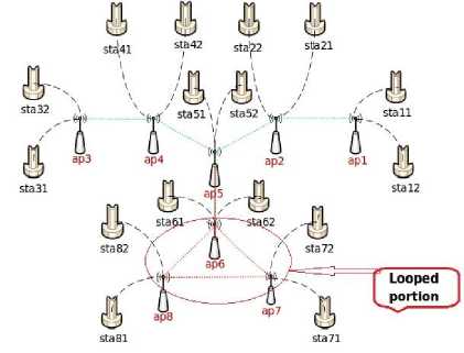
Fig.1. Network Model with Loop Portion
-
A. Network topology having looped portion (without applying STP)
In this section, the SDWN model is considered with loop portion and STP has not applied yet. The topology has been run into Mininet-Wifi to evaluate the performance. After running successfully, it is required to test the connectivity among the STAs.
Connectivity test in Fig. 2, explicit that only 16 communicating route has connected successfully among 240 test result. The ICMP transmission and receive is only possible to the connected STAs. But 93% of connections are dropped. This causes a large amount of packet lost.
** Starting network
** Ping: testing ping reachability tall -> Stal2 xxxxxxxxxxxxxx tal2 -> Stall XXXXXXXXXXXXXX ta21 -> X X Sta22 XXXXXXXXXXXX ta22 -=> X X Sta21 XXXXXXXXXXXX ta31 -> X X X X Sta32 XXXXXXXXXX ta32 -> X X X X Sta31 XXXXXXXXXX ta41 -=> X X X X X X Sta42 XXXXXXXX ta42 -=> X X X X X X Sta41 XXXXXXXX tasi -> XXXXXXXX Sta52 X X X X X X ta52 -> XXXXXXXX Stasi X X X X X X ta61 -> XXXXXXXXXX Sta62 X X X X ta62 -=> XXXXXXXXXX Sta61 X X X X ta71 -> XXXXXXXXXXXX Sta72 X X ta72 -> XXXXXXXXXXXX Sta71 X X ta81 -=► XXXXXXXXXXXXXX Sta82 ta82 -=> XXXXXXXXXXXXXX Sta81 ■** Results: 93% dropped (16/240 received) ** Running CLI
Fig.2. Connectivity Test
The ‘X’ sign in Fig. 2, indicates that, the echo request packets cannot be transmitted between these two stations. When ICMP message is exchanged between these stations, it may be dropped and more delay will be occurred. Timeout or No route found may be resulted.
Fig. 1, shows network loop has been found among ap5, ap6, ap7 and ap8. This situation prevents to communicate the corresponding base stations (STAs) under each access point (AP) with other base stations (STAs) of different
Access Points (APs). Then the source ARP broadcast request messages cannot be reached in its destination. The destination is unreachable because the data streams find loop sections and causes the continuous occurrence of broadcast streams until it is time out. This may reduce the network performance significantly. That means it will not possible to get the exact result of QoS analysis.
The destination STA resolves the physical address of the source STA to start execution. The source is waiting for an ARP reply message from the destination. To evaluate such a case any two STAs of different APs (suppose sta11 and sta81) can be defined as source and destination respectively. If the source request messages cannot reach its destination the ping result shows destination is unreachable. This happens when the ARP requesting broadcast messages cannot reach to its destination for a network's loop. Fig. 3, display the ping statistics of 10 packet transmission between the source and destination. The output will be 9 bit errors, 100% packet lost and a 1046 ms delay. This result shows that network traffic is a failure. When this situation arises, it is quite impossible to get the exact QoS performance. Thus, it must be ensured to transfer the packet smoothly.
PING 192.168.6.81 (192.168.9.81) 56(84) bytes of data.
From 192.168,0.11 icmp_seq=l Destination Host Unreachable
From 192.168.6.11 icmp_seq=2 Destination Host Unreachable
From 192.168.6.11 icmp_seq=3 Destination Host Unreachable
From 192.168.6.11 icmp_seq=4 Destination Host Unreachable
From 192.168.6.11 icmp_seq=5 Destination Host Unreachable
From 192.168.6.11 icnp_seq=6 Destination Host Unreachable
From 192.168.6.11 icmp_seq=7 Destination Host Unreachable
From 192.168.6.11 icmp_seq=8 Destination Host Unreachable
From 192.168.6.11 icmp_seq=9 Destination Host Unreachable
--- 192.168.9.81 ping statistics --
10 packets transmitted, 6 received, +9 errors, 109% packet loss, tine 9646ms
Fig.3. Transmission Result between Sta11 and sta81
To evaluate the network service, it needs to ensure a loop free architecture. Let analyze the network performance by using STP.
-
B. QoS measurement of SDWN using STP
The Spanning Tree Protocol is used to reduce the network's loop. The STP mechanism first identifies the active redundant links of a topology to prevent the possible looping by suppressing them. Thus the promising SDWN architecture (network model with STP) can be obtained by applying STP which breaks the link between ap8 and ap7. In the spanning tree structure the total numbers of the optimal link ( Nol ) between the access points across the network can be defined as:
Nol = Napi – 1; when Napi > 1 (1)
Otherwise,
Nol = 0; when Napi < 1
The number of the Access Point is = Napi.
The number of total links between the APs across the network is = Nol.
After suppressing the redundant link between APs the network should have total link equal to Nol . When Nol is greater than 0 the transmission can take place. Then the topology has been run again into mininet-Wifi following STP. The new configuring network performance shows an optimal result with minimum packet drops and maximum reachability. It helps to obtain a complete analysis of simulation result that focus on the performance of the QoS parameters.
Algorithm1. Pseudocode description of SDWN with STP.
-
1 number of access point=Nap; number of base stations=Nsta.
Set Mac and IP for all base stations.
Set position, Id and mode for all access points
-
2 For (i=1:Nap)
-
3 For (i=1:Nsta)
-
4 Add.link (APi, STAij)
-
5 For (i=1:Nap)
-
6 while (APi.neighbour!=visited)
-
7 { Add.link (APi, APi.neighbour)
-
8 APi.neighbour=visited
}
-
9 start Controller C
-
10 For (i=1:Nap)
-
11 start (APi, C)
-
VII. Result and Analysis
QoS provisioning encompasses the ability of the network to provide QoS to the end users such that it meets the service needs of certain applications. This section describes the QoS parameters, related to several aspects of the network service. In this simulation transmission delay, max-min RTT, bandwidth utilization, average jitter, throughputs and packet loss rate has been considered. The STA11 is considered as source base station and all other base stations are considered as destinations. This process can evaluate the QoS performance in every portions of the network.
-
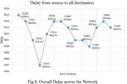
A. Transmission Delay
The measurement of delay is the total time taken for a message to travel from source to destination across the network that will experience due to network congestion. Accounting time consumed in different part of a network to send packets from source to destination can be expressed as follows.
D end-end = N [dproc + dqueue + dtrans+ dprop] (2)
Where,
D end-end = End - to - End Delay;
dproc = Processing Delay;
dqueue= Queuing Delay dtrans = Transmission Delay;
dprop = Propagation Delay;
N = Number of links (Number of routers + 1)
At first the packet header needs nodal processing to check bit errors and determine transmission link that will result processing delay. Transmission delay is the amount of time to push the packet’s bits onto the link as a function of packet length (L) and link bandwidth (R) that can be defined as L/R. In wireless communication the propagation delay depends on the speed of light (c) in the medium for a signal to reach its destination, that means the propagation time can be defined as d/c where d is the distance between the source and destination. This experiment defines STA11 as the source and all other STAs as destined to test the reachability in every station. The execution of (2) can be computed as D STA11-STA82 = N [d trans + d prop + d proc + d queue ] = 9013ms. Fig. 4, shows the amount of transmission delay for each of the destination STAs from the source STA.
-
B. Round Trip Time (response time/latency)
RTT is the time between a request for data and the complete return of that data from source to destination. It can be obtained by performing ping between the source and destination. Actually the interval between the probe packets are considered in latency whether round trip time has also taken the amount of time for packet processing at the destination. The ping results of latency for each packet must between the range of min RTT and max RTT.
Equation (3), calculates the RTT for a packet transmitted from source to destination. RTT includes time ‘ Td’ at receiving packet and ‘ Ts’ at sending packet. The maximum, minimum, average RTT can be calculated from the n’th numbers of packet.
L=i × (Td – Ts). (3)
L=Round trip time i=interval between the probe packets
Td =time needed to receive the packet
Ts =time needed to send the packet max RTT=Max(L1,L2,……..,Ln) min RTT=Min(L1,L2,……….,Ln) Average RTT= (L1+L2+…… +Ln) /n Where, n= number of packets to be transmitted.
Fig. 5, shows the maximum and minimum RTT in each of the destination STAs. From this it can be defined that the obtaining RTT values will be the range of max RTT and min RTT for each STAs.
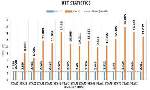
Fig.5. RTT Statistics of Min and Max
-
C. Bandwidth Measurement
The overall performance of a network depends on the efficient utilization of bandwidth. Because the rate of packet drop depends much on it. The effective bandwidth can be calculated as (4).
Amount of bits
( Time duration x Speed of transmission medium )
The amount of bandwidth is the potential measurement of data across the transmission medium. In this experiment, the TCP achievable bandwidth is calculated in both source (STA11) and destination (STA12 to
STA82) for a single packet transmission. For each transmission the source shows almost same bandwidth performance. The destinations show maximum bandwidth utilization. This graph is as follows.
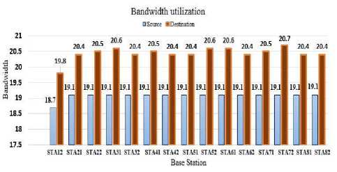
Fig.6. Bandwidth Source Vs Destinations.
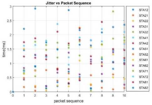
Fig.7. Jitter Vs Packet Sequence.
E. Throughput
Fig. 6, shows the execution results of bandwidth utilization at source and destination. Each STA has two bar units, the first one is source bandwidth and the second one is for destination bandwidth. This experiment defines STA11 as the source for all other destination STAs.
-
D. Jitter
Jitter or packet delay variation is the variation of delay at packet transmission. Delay variation can be introduced as the time variation between packets arriving along the communication path. In this simulation UDP background traffic has generated to measure accurate result. Packet delay variation (PDV) can be also expressed as the average of the deviation from the network mean latency. The delay variation of packet depends on the successive transit delay between the entry and the exit nodes. Equation (5), shows the average of the absolute difference in the time it took for successive packets to reach the destination.
E|( Jn - Tn)/+1 -(Jn - Tn)J n-1
Here,
Jn = PacketArrival
Tn = PacketStart
Fig. 7, shows the result of jitter against packet sequence for each destination. The number of transmitted packets is 10 for each source to destination. Note that the number mentioned here is not the exact representation of the data. They are thinking about to make the calculation clear. Thus the average jitter is the average of delay difference in successive packet.
Throughput is the actual measurement of data transferred through a network. It can be defined as the data transfer rate that is delivered to all terminals across the network. It is measured in terms of the total number of transferring packets divided by the total amount of time it has taken during transmission. This can be obtained it from:
( number of transmitted packets x bandwidth ) ^
transmission time
The number of transmitted packets indicates the actual number of packets reaching the destination, bandwidth is the potential measurement of data transmission, transmission time was calculated as the difference between the time the first packet started and the time the last packet reached the destination This experiment calculate the amount of throughput for the transmission of ten packets for every station (STA12 to STA82) from the source station (STA11). Fig. 8, is the representation of throughput measurement against the number of packet sequence.
F. Packet Loss Rate (Lost/Total)
Packet loss is occurred due to bit errors, erroneous wireless network, insufficient buffers, network congestion, overloaded channel, etc. To ensure a high
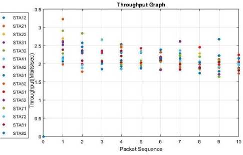
Fig.8. Throughput Vs Packet Sequence
QoS, packet loss rate should be minimum. In this simulation of SDWN the packet lost rate has been observed. Packet loss can be measured as the percentage of lost packets with respect to the packet sent. Equation (8) can be derived to detect the packet loss using TCP and UDP measurements.
PLtotal = (PStotal /PRtotal) × 100%. (7)
Where
PLtotal = Total packet loss
PStotal = Total packets sent
PRtotal = Total packets received
The total number of packet drops during transmission between sources and destination is almost minimized, that causes the better performance of network protocol.
The details of the QoS performance for SDWN has presented in the result analysis section. The goal was to compare different types of service flow with respect to QoS parameters such as delay, max-min RTT, bandwidth, average jitter, throughput and packet loss rate. An SDN based wireless environment is used to simulate and analyze the various network conditions and load on QoS parameters. The mean deviation for any distinct parameter is almost minimum in each of the base stations. This proves that the number of increasing base station has no effect on the QoS performance across the network. Thus, it has become a smooth and suitable architecture to operate.
-
VIII. Conclusions
In the paper, the general concepts of Quality of service (QoS) in SDN based wireless network was studied. The STP network architecture was presented and the OpenFlow features that enable end-to-end QoS mechanism in the network were discussed. Various QoS parameters that are supported in SDWN were simulated using mininet-Wifi.
The performance of different QoS parameters like bandwidth utilization, max/min jitter, throughput, packet loss, and average delay were analyzed. In general, it was observed that the network could not perform accurately in the loop portion. It can be concluded from the results that the STP protocol has applied across the network to make the network more smooth and measure the exact performance. The TCP and UDP flow is indeed to analyze the performance between senders and receivers. Maximum and minimum bandwidth utilized at each STA was obtained from the flow of network traffics. Ping command generated the total delay and round trip time (rtt) between the source STA11 and each of the destination STAs. UDP test captured affecting throughput, network jitter, and packet loss during transmission.
The experiment has lower packet loss and better performance in respect to the packet out of order delivery. During the analysis STP performs an efficient result than without STP in the network. In this technology the performance of QoS parameters is more efficient as the network control is outside of the forwarding control. Load balancing, queue management, QoS improvement, network protocol analysis of an SDN based wireless network may be the future scope on the basis of this methodology.
References Analysis of QoS in Software Defined Wireless Network with Spanning Tree Protocol
- "Software-Defined Networking (SDN) Definition" https://www.opennetworking.org/sdn-resources/sdn-definition [Online; Accessed: 23-06-2016].
- R. k Jha, P. Kharga, I. Z. Bholebawa, S. Satyarthi, S. Kumari, and others, "OpenFlow Technology: A Journey of Simulation Tools," International Journal of Computer Network and Information Security, vol. 6, no. 11, p. 49, 2014.
- I. Z. Bholebawa, R. K. Jha, and U. D. Dalal, "Performance Analysis of Proposed OpenFlow-Based Network Architecture Using Mininet," Wireless Pers Commun, vol. 86, no. 2, pp. 943–958, Jul. 2015.
- Deepika M S, K N Rama Mohan babu , "An Approach to Effective Bandwidth Utilization using Software Define Networking," International Journal of Computer Science and Information Technologies, Vol. 5 (4), 2014, 5571-5574.
- S. Costanzo, L. Galluccio, G. Morabito, and S. Palazzo, "Software Defined Wireless Networks: Unbridling SDNs," presented at the 2012 European Workshop on Software Defined Networking, pp. 1–6, 2012.
- R. R. Fontes, S. Afzal, S. H. B. Brito, M. A. S. Santos, and C. E. Rothenberg, "Mininet-WiFi: Emulating Software- Defined Wireless Networks," presented at the 11th International Conference on Network and Service Management (CNSM), , pp. 384–389, , 2015.
- "Spanning Tree" https://osrg.github.io/ryu-book/en/html/spanning_tree.html [Online; Accessed: 23-06-2016].
- "Understanding Spanning Tree Protocols – STP, RSTP, MSTP", http://www.excitingip.com/1688/understanding- spanning-tree-protocols-stp-rstp-mstp/ [Online; Accessed: 29-06-2016].
- "Iperf–The TCP/UDP Bandwidth Measurement Tool" http://iperf.fr/ [Online; Accessed: 25-06-2016].
- Idris Zoher Bholebawa*, Upena D. Dalal, "Design and Performance Analysis of OpenFlow-Enabled Network Topologies Using Mininet," International Journal of Computer and Communication Engineering, Volume 5, Number 6, November 2016.
- D. Raumer, L. Schwaighofer, and G. Carle, "MonSamp: A Distributed SDN Application for QoS Monitoring," presented at the Computer Science and Information Systems (FedCSIS),Federated Conference on, 2014, pp. 961–968, 2014.
- F. Keti and S. Askar, "Emulation of Software Defined Networks Using Mininet in Different Simulation Environments," presented at the 2015 6th International Conference on Intelligent Systems, Modelling and Simulation, pp. 205–210, 2015.
- Tibor Cinkler, Istv´an Moldov´an, Andr´as Kern, Csaba Lukovszki, Gyula Sallai, "Optimizing QoS Aware Ethernet Spanning Trees" Authorized licensed use limited to: BME OMIKK. Downloaded on November 21, 2008 at 06:01 from IEEE Xplore.
- I. D. Irawati and M. Nuruzzamanirridha, "Spanning Tree Protocol Simulation Based on Software Defined Network Using Mininet Emulator," presented at the International Conference on Soft Computing, Intelligence Systems, and Information Technology, pp. 395–403, 2015.
- "The Network Simulator - ns-2," http://www.isi.edu/nsnam/ns/, [Online; Accessed: 21-06-2016].
- "ns-3," https://www.nsnam.org/, [Online; Accessed: 21-06-2016].
- "OMNET++," https://omnetpp.org/, [Online; Accessed: 21-06-2016].
- "Riverbed," http://www.riverbed.com/, [Online; Accessed: 22-06-2015].
- A. Ishimori, F. Farias, E. Cerqueira, and A. Abelém, "Control of Multiple Packet Schedulers for Improving QoS on OpenFlow/SDN Networking," presented at the 2013 Second European Workshop on Software Defined Networks, pp. 81–86, 2013.
- C. J. Bernardos, A. de la Oliva, P. Serrano, A. Banchs, L. M. Contreras, H. Jin, and J. C. Zuniga, "An Architecture for Software Defined Wireless Networking," IEEE Wireless Communications, vol. 21, no. 3, pp. 52–61, Jun. 2014.
- B. A. A. Nunes, M. Mendonca, X.-N. Nguyen, K. Obraczka, and T. Turletti, "A Survey of Software-Defined Networking: Past, Present, and Future of Programmable Networks," IEEE Communications Surveys & Tutorials, vol. 16, no. 3, pp. 1617–1634, Third Quarter 2014.
- S. Kumar, M. Dave, and S. Dahiya, "QoS Enabled Probabilistic Routing for Heterogeneous Wireless Sensor Networks," International Journal of Computer Network and Information Security, vol. 5, no. 4, p. 31, 2013.
- Y. Lim, H. Yu, S. Das, S. S. Lee, and M. Gerla, "QoS Aware Multiple Spanning Tree Mechanism Over a Bridged LAN environment," in Global Telecommunications Conference, 2003. GLOBECOM'03. IEEE, 2003, vol. 6, pp. 3068–3072.
- W. Kim, P. Sharma, J. Lee, S. Banerjee, J. Tourrilhes, Sung-Ju Lee, and P. Yalagandula., "Automated and Scalable QoS Control for Network Convergence." INM/WREN, vol. 10, no. 1, pp. 1–1, 2010.
