Analysis of the stress-deformed state of the prismatic support of the lever calibration device of test stands for liquid rocket engines

Author: Begishev A.M., Zhuravlev V.Y., Nazarov V.P., Torgashin А.S.
Journal: Siberian Aerospace Journal @vestnik-sibsau-en
Section: Aviation and spacecraft engineering
Article in issue: 1 vol.23, 2022.
Free access
The force measuring device is a part of the bench force measurement system required for direct meas-urement of the rocket engine thrust during the test. One of the common types of force-measuring device calibration systems is a lever-type calibration device. The simplicity of the kinematic scheme is one of the main advantages of its use as a calibration system. Along with this, the disadvantages of this scheme are concentrated in the supporting elements of the lever system, since it is the wear of the supports that leads to the accumulation of a systematic error of the entire system with a proportional deterioration in the accura-cy of the force measurement process. The aim of the work was to analyze the features of prismatic supports used as part of a lever-based calibration device of a force-measuring device, as well as to simulate the stress-strain state of a model of a real prismatic support used in an existing force-measuring system. The work considers the closest theoretical information associated with calculating the stress distribution in the wedge and half-plane in accordance with the plane problem of the theory of elasticity. The selection of the mechanical properties of materials was carried out depending on the specified hardness indicators, as well as the modeling of the contact problem in a given prismatic support, depending on the angle of inclination of the prism in relation to the pad, using the static analysis of the Solidworks Simulation software package. In this work the calculation results are given and also conclusions are drawn.
Firing test stand of LRE, force-measuring device, prismatic support, Solidworks Simulation system, static analysis of the stress state
Short address: https://sciup.org/148329607
IDR: 148329607 | UDC: 621.45.018.2 | DOI: 10.31772/2712-8970-2022-23-1-54-63
Text of the scientific article Analysis of the stress-deformed state of the prismatic support of the lever calibration device of test stands for liquid rocket engines
The creation of propulsion systems (PS) of rocket and space complexes requires both design and calculation work and a large amount of testing of engines, propulsion systems and their systems in bench and flight conditions. Ground testing is carried out on prototype engines and is an important and most time-consuming research and development process. In the course of the fire test, a large number of engine operating parameters are recorded, the final analysis of which determines whether the recorded readings correspond to the calculated ones. Determining the thrust force of the tested rocket engine is possible in two ways: directly, using a special bench system for measuring forces, or indirectly, when, based on the recorded data, the magnitude of the thrust force is determined analytically [1]. The system for measuring the forces of test benches for liquid rocket engines (LRE) involves the use of a special force measuring device. The force measuring device consists of a machine tool, a measuring and calibration system. Various schemes can be used as a measuring system, including primary force transducers. Due to the fact that the measurement of the LRE thrust force is associated with taking into account the influence of other bench systems on the process of force measurement, systems and methods for accounting for these negative effects are provided. Many impacts are of a permanent nature and are taken into account analytically before the process of preparing the rocket engine for testing. The impacts of a variable nature are taken into account with the help of a calibration system designed for calibrating the sensors of the force measuring device system. Calibration is carried out by applying forces of a strictly defined value to the force measuring machine, thereby simulating the effect of the axial thrust of the engine on the measuring system [2]. The calibration error, in turn, is the sum of the systematic error of the force setting means, the random component of the error during calibration, and the error of the recording device [3]. Due to the fact that the force from the calibration system is taken as an exemplary one, the relationship between the force acting on the machine and the readings of the measuring system is determined, in which such phenomena as the effect of the rigidity of all technological connections between bench systems and the engine, etc. [4]. The choice of the type of calibration system, as well as the version of execution, will depend on the design of the machine used in the force measuring device. There are several well-established calibration systems used on high-power LRE test benches: hydraulic calibration system. In the case of hydraulic calibration system, the system is connected by levers to a movable frame, through which a known force can be applied to the latter, corresponding in direction to the thrust of the engine. All connections of the levers with the rest of the calibration system are carried out using prismatic supports. Due to its constructive simplicity, this scheme has found wide distribution, despite its specific disadvantages, which are concentrated in the hinged support mechanisms of the lever systems.
Structural scheme of the research object
The error of the lever-type calibration system depends on the accuracy of the gear ratios of the levers, the rigidity of the levers, and also on the condition of the surfaces of the prismatic supports, since they have increased wear under vibration loads. The main elements of the support are the pad and the prism, which are made of high-quality steels. An example of this support is shown in fig. 1. The hardness of the pad should be 3 to 5 units of the Rockwell “C” scale higher than the hardness of the prism.
The following basic requirements are imposed on prismatic supports: parallelism of the working blades of the prisms, minimum radii of the working blades, absence of chips (dents, nicks) on the working blades. The disadvantages of prismatic bearings include: increased wear under vibration loads (which leads to a decrease in the sensitivity of the system and measurement accuracy), inability to perceive lateral loads, difficulty in transferring alternating loads (preloading is required).
During the design process, the design of the levers is laid taking into account a certain level of elastic deflection of the lever arms under the design load. For this reason, levers are massive elements that retain their rigidity during operation. When designing supports, they proceed from the selection of the geometry of materials, in which the operation of the support occurs with minimal friction and provided that the maximum design load does not cause elastic deformation of the working elements. In this regard, the main attention in terms of routine maintenance is paid to the periodic check of the condition of the elements of the supports and, if necessary, their replacement.
Based on the foregoing, for the correct operation of the lever calibration device, it is important to have a specific idea of the stress-strain state in which the supports are in the process of transferring force through the leverage systems. To carry out the analysis, as a design scheme, we take a prismatic support operating as part of the force measuring device of test benches of enterprises in the rocket and space industry, shown in Fig. 1. The general scheme of this force measuring device is presented in the source [5].
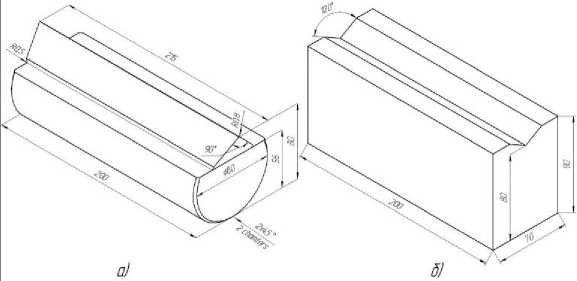
Fi 1. Dimensional diagram of the prismatic sup ort: а б a – prism; b – pad
Рис. 1. Габаритная схема призматической опоры: а – призма; б – подушка
Theoretical statement of the research problem
Let us present the calculation formula closest to the problem posed for determining the stress in a wedge of unit thickness under the action of a concentrated force applied to the top [6]. This formula is derived in a polar coordinate system and refers to a plane problem of elasticity theory:
° r
2 P ( sin y- sin ф cos y- cos ф ------
r I 2a- sin2a 2a + sin2a where in accordance with the calculation scheme shown in Fig. 2: P is the force applied to the vertex of the wedge; α is half the angle of the wedge solution; γ is the angle of the force direction to the axis of symmetry of the wedge; φ is the polar angle; r is the polar radius.
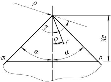
Fig. 2. Wedge under concentrated force
Рис. 2. Клин под действием сосредоточенной силы
Based on the formulas for the relationship of coordinates of an arbitrary point in the polar and Cartesian coordinate systems, the relationship between normal stresses in the polar and Cartesian coordinate systems, as well as boundary conditions on the faces of the wedge [7; 8], it is possible to deduce the dependencies of normal stresses in translation into the Cartesian coordinate system
о
2 P - x 2
у/ x 2 + У 2
cosy-x x2 + y2 - (2a + sin 2a)
sin у - y
1 x 2 + y 2 - (2 a- sin 2 a ) ?
о
2 P - y

cos y- x sin y- y
^ 7 x 2 + y 2 - (2 a + sin 2 a ) x 2 + y 2 - (2 a- sin 2 a ) ?
T xy
xy 2 P cos y- x sin y- y
— -----— - —, = - —. =--I--, =---------------- x + y x2 + y2 ^x2 + y2 -(2a + sin2a) x2 + y2 -(2a-sin2a)?
In accordance with these formulas, it is possible to determine stress diagrams σ x , σ y , τ xy , in sections at some distance from the top of the wedge, under conditions of different angles of the wedge opening, different angles of direction of the concentrated force. Let us consider a particular case of wedge compression by a concentrated force applied in the vertical direction (in formulas (2), (3), (4) the direction angle of the force is assumed to be γ = 0º). In this case, the compressed wedge, except from the standpoint of the theory of elasticity, can be considered from the standpoint of the resistance of materials as a rod of variable cross section, then for a certain cross section mn at a distance x 0 from the vertex, we obtain
о
x
PP
- - -
.
F ( x ) 2 x 0 - tg a
In this case, the stresses σ x are uniformly distributed over the section. At an angle γ = 30º, these stresses are 17% less in absolute value than the highest stresses obtained using the exact formulas of the theory of elasticity (2), (3), (4). As γ increases, this discrepancy increases. For example, at γ = 45º it becomes equal to 36%. Stresses σ y , τ xy , which are not taken into account in the resistance of materials, have the same order with the stresses σ x .
It is worth noting the following feature: formulas for calculating the wedge (2), (3), (4) are valid for the case of a force acting on a wedge with an opening angle of 2γ = 180º or more. In this case, the wedge degenerates into a half-plane, i.e., a plate of unit thickness extending indefinitely on one side of the horizontal boundary. A plane stress state arises in the half-plane (the so-called Flaman problem). This imitates the application of a concentrated force to the pad of a prismatic support, according to the type presented in fig. 1b.
The calculation of the wedge according to the formulas of the theory of elasticity assumes that the force is applied to the edge of the wedge, which does not have a rounding, but in reality, in the prismatic support, the minimum radius is set on the prism blade, in order to avoid edge chipping in the event of shock loads and thereby to improve the performance of the support. But taking into account in this question the criterion of the desire to minimize the rounding of the blade, the above formulas of the theory of elasticity for calculating the distribution of stresses in individual elements of the prismatic support can be considered valid.
At its core, the work of a prismatic support is a contact task, in which the support element under load acts on another element. In the case of geometric features in terms of rounding edges, etc., which directly affect the contact interaction between elements, the above section of the theory of elasticity does not give answers. It was decided to calculate the contact interactions in a particular support by the finite element method, using one of the appropriate software packages.
Research methodology
It was decided to carry out the calculation using the Solidworks Simulation software package. The geometric dimensions of the elements of the studied support are shown in fig. 1. A prism with an opening angle of 90º and a radius rounding of the blade edge r = 0.8mm is made of U8 tool steel, in the manufacture of which hot-rolled steel of round section is used as a billet. This steel has increased strength, significant hardness, which is provided by staged heat treatment, and has a high ability to endure significant vibrational and mechanical loads in conditions that do not cause heating of the working edge. The pad with an opening angle of 120º is made of U9 tool steel without rounding the inner edge. The steel has a slightly higher carbon content compared to U8 steel, but in general it has similar mechanical characteristics.
In accordance with the design documentation for the support elements, the required ranges of Rockwell hardness (HRC) values are specified, the average values of which are listed in table. 1. The values of such characteristics for steels as the modulus of elasticity ( E ), mass density (ρ), shear modulus ( G ), Poisson's ratio (μ) are listed in Table. 1 based on the handbook of grade steels [9]. In the process of searching in various sources, there was not found enough data to correlate the tensile strength and yield strength under various heat treatment conditions, which would provide the necessary surface hardness. Due with this, it was decided, on the basis of the calculations given in the source [10], to determine the mechanical properties of metals in terms of hardness. To do this, the known values of Rockwell hardness (HRC) had to be converted into the corresponding readings of Brinell hardness (HB), for which the source conversion table [9] was used. For the convenience of subsequent actions, these values should be converted to the dimension [MPa]. In [11], the following empirical dependences of Brinell hardness (HB) and ultimate strength and yield strength, derived from the analysis of experimental results, are given:
σ в = 0,333 ⋅ НВ; (6)
σ 0,2 =
0,3 ⋅ НВ - 50
1,03
Based on formulas (6), (7) we will put calculated tensile strengths and yield strengths of the support elements in table 1, taking into account the previously derived readings of Brinell hardness (HB).
Table 1
Mechanical properties of materials of support elements
|
Steel |
Hardness |
σ в, MPa |
σ 0,2 , MPa |
Е, GPa |
G, GPa |
μ |
ρ, kg/m3 |
|||
|
HRC |
HB, kgf/mm2 |
HB, MPa |
||||||||
|
Prism |
U8 |
60 |
611 |
5992 |
1995 |
1697 |
209 |
81 |
0,25 |
7839 |
|
Pad |
U9 |
63 |
655 |
6423 |
2139 |
1822 |
207 |
79 |
0,25 |
7745 |
The prism is fixed by pressing its cylindrical part into the groove of the lever. As a result, the prism perceives the load from the lever over the area of the cylindrical part of its base, in connection with which this particular face of the prism was chosen as the platform for applying force in the process of calculating the prism support. As a design load, it is assumed that a force of 50,000 kgf (490.3 kN) is applied to the cylindrical base of the prism. A real pad also has a radius base in its design, but since the base of the pillow is fixed in the calculation process and only perceives the load, it was decided to simplify the design of the pad model. Fig. 3 shows a model of a support with a constructed grid, as well as a design scheme, according to which a known force P is applied to a cylindrical base. This support has a maximum rotation of the prism relative to the pad of 30º, due with this, it was decided to analyze the state of the support at different positions of the prism relative to the point O (the center of the radius rounding of the prism blade) with a step of 3º. The computational grid of the model has local compactions at the points of contact of the elements to improve the accuracy of the results and save computer calculating resources [12].
In addition to the fixed face, it is necessary to apply the boundary condition “Connections – no penetration” at the points of contact of the parts with each other. Due to the fact that the contact areas at the initial stage are segments formed by touching the prism blade and the pad faces, for further correct calculation it is necessary to impose boundary conditions on the faces formed by this very contact. All the necessary steps to launch the solution have been completed, you can proceed to the implementation of the solution.
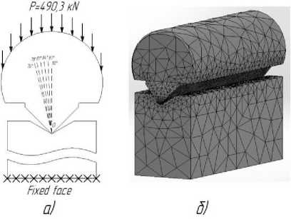
Fig. 3. Calculation model: a – loading scheme; b – mesh model
Рис. 3. Расчетная модель: а – схема нагружения; б – модель с построенной сеткой
Calculation results of the prismatic support
At the end of the calculation, the following results of stress, displacement and deformation are presented [13]. Figures 4, 5 show the stress-strain state of the prismatic support and the concentration of stress on the surface of the prism blade in Mises stresses, displacement diagrams and relative deformation under the influence of the prism at an angle of 90 °.
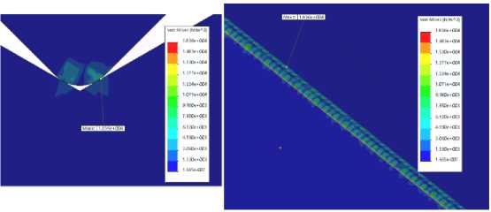
Fig. 4. Stress distribution in the contact zone of the prismatic support
Рис. 4. Распределение напряжений в зоне контакта призматической опоры
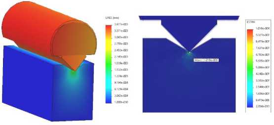
Fig. 5. Displacement plot and relative deformation plot
Рис. 5. Эпюра перемещений и эпюра относительной деформации
As it can be seen from the distribution of equivalent stresses, the maximum stress is formed in the area of the prism blade, in order to determine the maximum stress on the surface of the pad, it is necessary to use a probing tool and, selecting the contact faces of the pad for analysis, determine the maximum voltage value [14].
Based on the above manipulations, the maximum stresses in the support elements were checked at different angles of the prism impact on the pad. The results of the analysis are listed in table 2. For clarity of the results, the data are converted into a graph shown in figure 6. An angle of 76º was chosen as the extreme position of the prism, since in this case there is no influence of the contact of the working face of the prism with the face of the pad.
Table 2
Maximum equivalent stresses at different positions of the prism relative to the pad
|
The angle of impact of the prism on the pad |
||||||
|
90º |
87º |
84º |
81º |
78º |
76º |
|
|
σ max on the surface of the prism (Von Mises), kPa |
18,36 |
19,74 |
21,68 |
25,47 |
27,71 |
23,95 |
|
σ max on the surface of the pфв (Von Mises), kPa |
2,92 |
2,884 |
3,04 |
3,71 |
3,61 |
3,66 |
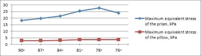
Fig. 6. A graph of the change in the maximum equivalent stresses with a change in the position of the prism relative to the pad
Рис. 6. График изменения максимальных эквивалентных напряжений с изменением положения призмы относительно подушки
The equivalent maximum prism stresses are higher than the pad stresses. The calculation of this support showed that when a significant force is applied to the base of the prism, stress values arise that are much lower compared to the yield strength for given materials. This point indicates that the operation of the support occurs in the zone of elastic deformations and the lever calibration device, which has this prismatic support in its design, under conditions of operation with a static load, is not prone to loss of accuracy during operation due to the accumulation of deformations in the support.
Conclusion
The existing calibration lever systems in the field of rocket engine testing are experiencing a period of obsolescence. On vertical firing stands for testing powerful rocket engines, the force measuring device is a bearing construction. In this case, the transition from a lever calibration system to another type, due to the difference in performance, will require a complete reworking of the force measuring device, which cannot but affect the complexity and cost of the process. Along with this, there are concepts of improving the lever calibration system by adding an additional force-setting device to the composition: hydraulic (source [5]) or electromechanical type (source [15]). These schemes assume an increase in the drive force set through the lever system to the required values. In this regard, it is important to be able to predict and analyze the process based on modern design techniques. In this paper, a static analysis of the prismatic support model was carried out using the Solidworks Simulation software package. All the boundary conditions for the calculation are listed, and a model of the stressstrain state of a prismatic support under different loading conditions is obtained.
References Analysis of the stress-deformed state of the prismatic support of the lever calibration device of test stands for liquid rocket engines
- Galeev A. G. Osnovy ustrojstva ispytatel’nyh stendov dlya otrabotki zhidkostnyh raketnyh dvigateley i dvigatel’nyh ustanovok. Rukovodstvo dlya inzhenerov-ispytateley [Fundamentals of test benches for testing liquid propellant rocket engines and propulsion systems. Test Engineer Guide]. Peresvet, Izd-vo FKP “NIC RKP” Publ., 2010, 178 p.
- Galeev G. A., Ivanov V. N., Katenin A. V. et al. Metodologiya eksperimental’noy otrabotki ZHRD i DU, osnovy provedeniya ispytaniy i ustroystva ispytatel’nyh stendov [Methodology for the experimental development of LRE and PS, the basics of testing and test bench devices]. Kirov, MCNIP Publ., 2015, 436 p.
- Kleckers T., Dr. A. Schaefer Force Calibration with Build Up Systems. 18th International Congress of Metrology, 2017. Doi: 10.1051/metrology/201714009.
- Kolymagin A. N., Medvedev V. K. [Accounting for the Influence of the Rigidity of the Bonds of the Force-Measuring Device in Measuring the Thrust of a LRE on a Firing Bench]. Trudy NPO Energomash im. akademika Glushko. 2012, P. 286–289.
- Veselov A. V. [Modernization of the load-measuring device on the test benches of liquid rocket engines]. Reshetnevskie chteniya : materialy XXII Mezhdunar. nauch. konf. (12–16 noyabrya 2018, g. Krasnoyarsk) v 2 ch. [International science and research conference (in memory of the M. F. Reshetnev, general constructor of spase vehicles and rocket systems)]. Krasnoyarsk, 2018, P. 198–200.
- Birger I. A., Panovko Y. G. et al. Prochnost’, ustojchivost’, kolebaniya. Spravochnik v trekh tomah. Tom 1. [Strength, stability, vibrations. Handbook in three parts. Part 1]. Moscow, Mashi-nostroenie Publ., 1968, 821 p.
- Semenov D. L. [Solutions of problems of the theory of elasticity used to assess the contact strength and stiffness of machine parts]. Trudy Odesskogo politekhnicheskogo universiteta. 2007, P. 13–18.
- Nahatakyan F. G. [Solution of a plane contact problem of the theory of elasticity using an elastic half-space model]. Problemy mashinostroeniya i nadezhnosti mashin. 2011, P. 63–67.
- Zubchenko A. S., Koloskov M. M., Kashirskij Y. V. Marochnik stalej i splavov [Grade of steels and alloys]. Moscow, Mashinostroenie Publ., 2003, 784 p.
- Stoev P. I., Moshchenok V. I. [Determination of mechanical properties of metals and alloys by hardness]. Vestnik Har'kovskogo nacional'nogo universiteta im. V. N. Karazina. 2003, Vol. 601, No. 2, P. 106 (In Russ.).
- Markovec M. P. Opredelenie mekhanicheskih svojstv metallov po tverdosti [Determination of the mechanical properties of metals by hardness]. Moscow, Mashinostroenie Publ., 1979, 191 p.
- Dushin I. F., Maskajkina S. E., Polueshina N. I. [Strength calculation of the gear pump casing using SolidWorks]. Vestnik Mordovskogo universiteta. 2014, No. 1-2, P. 154–160.
- Gadiev D. A. [Optimizing Design Features Using Solidworks]. Nauchno-prakticheskie issledo-vaniya. 2020, No. 1–4, P. 27–31.
- Zen’kov E. V. [Estimation of the stress state and fatigue life of a prismatic sample based on numerical simulation]. Vestnik Irkutskogo gosudarstvennogo tekhnicheskogo universiteta. 2013, No. 5(76), P. 32–38.
- Begishev A. M., Zhuravlev V. Yu., Torgashin A. S. [Features and possible way of moderniza-tion of force-measuring devices of test stands of liquid-propellant rocket engines]. Sibirskij zhurnal nauki i tekhnologiy. 2020, Vol. 21, No. 1, P. 62–70.
