Analyzing Multiple Routing Configuration

Author: Meenakshi Moza, Suresh Kumar
Journal: International Journal of Computer Network and Information Security(IJCNIS) @ijcnis
Article in issue: 5 vol.8, 2016.
Free access
Internet plays a vital role in communication. Determination of internet capability is done by Routing protocol. After a network fails, routing protocols have very slow convergence rate, which is a grave problem and needs to be tackled. Multiple Routing Configuration (MRC) is a technique which helps IP networks to recover very quickly from link and node failures. In MRC, packet forwarding persists on an optional link as soon as a failure is detected and additional information is always contained in the routers. This paper discusses the effect of packet size on throughput, packet delivery ratio, packet loss and delay for various routing protocols like OSPF, OSPF with 1 and 2 link breakage and MRC.
Congestion Avoidance, Router, Multipath routing configuration, Quality of Service, Back up configuration, Routing protocols, Traffic, Configuration
Short address: https://sciup.org/15011527
IDR: 15011527
Text of the scientific article Analyzing Multiple Routing Configuration
Published Online May 2016 in MECS
Global communication infrastructure is dominated by internet these days [9]. Internet usage is growing at an incredible rate. The reliability, availability and demand of the internet have increased exponentially in the last few years. In case of disruption in a link, millions of TCP connections or phone conversations are affected by unfavorable effects [7]. Recovering from failures has always been the basic design goal of internet [10]. In essence, IP networks are robust, as Interior Gateway Protocol, like OSPF update the forwarding information depending on the change of topology in case of failure. So when reconvergence takes place, complete distribution of the new link state information to every router in the network takes place. Each router calculates new routing tables after the new link state information is distributed. The IP reconvergence, takes time and node/link failures leads to routing instability. Invalid routes can be the reason for packet dropping. IP routing convergence steps include detection, dissemination and calculation of shortest paths. The convergence time for real time applications is quite large in spite of optimization of various steps of IP routing convergence. As network failures are short lived, quick triggering of reconvergence process can lead to network instability [4]. The reason behind the slow reconvergence process of IGP protocols is because of their reactive and global strategy. The
Multiple Routing Configuration (MRC), is a technique for node and link failure handling. The recovery mechanism in MRC is fast due to its proactive nature which involves resumption of forwarding of packets as soon as a failure is detected [1]. A set of backup configurations is created by making use of the network graph and related link weights. Manipulation of link weights is done in such a way that for any node/link failure, safe forwarding of packets to the destination is carried out by the node that detects the failure. In this paper the effect of packet size is analyzed on the protocols, namely: OSPF, OSPF with one and two link failures and MRC protocol.
This paper is organized into six sections. Section I provides the introduction of MRC. Section II discusses the literature review whileas, Section III gives detailed overview of MRC. Section IV deals with the methodology adopted and how NS3 is used for analyzing the behavior of the network under consideration. Section V talks about the variations of certain parameters for the routing protocols under consideration. In other words Section V comprises the result analysis. Section VI discusses the conclusions drawn and the future scope.
-
II. Literature Review
Shrikantet.al (2014) have discussed an Equal Cost Multipath Routing (ECMP) scheme in IP networks. Multiple equal cost paths are used from source to destination node in the network. The traffic is evenly distributed which helps in avoidance of congestion. No additional configuration is required as OSPF automatically calculates the equal cost paths. For multipath routing either multiple spanning trees or Directed Acyclic Graphs (DAG) are used. In the first case the header carries the routing table that is required for forwarding. In case, forwarding edge not being available, packet needs to be dropped because of packet looping, when it is moved back and forth between routing tables. When DAG’s are used, no guarantee can be given that a particular failure in, a link will not disconnect one or more nodes from destination. ECMP cannot cover all the cases for a single node and link recovery. Utilization of all edges does not happen here and therefore an extra bit is required in packet transferring. Recovery in case of failure is not 100% in this technique.
Shand et.al (2008) talk about IP Fast Rerouting on Multipath. Here one or more than one edge can be used for forwarding a packet for a particular destination. Two methods, namely Failure Insensitive Routing (FIR) and Not Via Addresses are used here. Shand states that in FIR, suppression of global updating is done by adjacent nodes whenever a link fails. Rerouting of packets is done locally which was otherwise to be done through failed link.. This method has a limitation that it does not guarantee recovery in case of more than one link failure. Not via address technique makes use of the concept of Redundant trees. Scalability is the issue here because when more than one link fails, a not via address has to be there for all possible failure scenarios.
Srinivasan et.al (2009) analyzed the technique of colored trees for disjoint multipath routing under node failure. He puts forward a method that helps to route packets with less routing table overhead and look up the time. It involves using colored trees. Construction of one red and one blue tree is carried out, rooted at the destination, in such a way, that path from any node to the destination, on the two trees are either node or link disjoint.The limitation is that at most, a packet can be transferred from one tree to another, only once, because this approach has a guarantee to recover from failure of single links. Another limitation of this method is, that in case of continuity, in switching of packets, between red and blue tree nodes, the packet transmission performance reduces.
Ohara et.al (2009) explained the Maximum Alternative Routing Algorithm. He puts forward a method that deals with construction of a DAG which makes use of all network edges. This helps in increasing the number of paths significantly, which can be put to use. Internet migration takes place from routing using a single path to multipath routing. This improves the recovery, from link to node failure, by the network and also the available bandwidth. The limitation of this method is that it does not provide any backup forwarding in case of link/node failure.
Telhourani et.al (2010) explained the Independent Directed Acyclic Graphs for Resilient Multipath Routing. He puts forward, that in this approach, the complete view of the network topology is present. The reason for this is that link state protocol is employed by the network. In this approach whenever red and blue DAG, are link or node independent, there is a guarantee of recovery from a single link or node failure, whenever there is a transfer of packet from one DAG to another. The fact that nodes can have many forwarding entries in each DAG, helps the network in tolerating multiple failures in this case.
-
III. Mrc Overview
Spread of traffic from source to destination node covering multiple paths through the network is called Multipath routing [5]. Multipath routing is a scheme of promise for availability improvement. Single path routing architecture is not very conducive to improving QOS. Better sharing of network resources, that are available, is the reason of improved performance in Multipath routing. Backup routing configurations form the basis of MRC and these configurations are resistant to certain link and node failures.
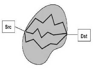
Fig.1. Multipath Routing
Configuration is a collection of link weights. For a particular configuration, which is resistant to node ‘n’ failure, assignment of link weights is carried out so that no traffic is routed through ‘n’. So when node ‘n’ fails, it affects only the traffic sent to and sent from ‘n’. When a configuration is such that it is resistant to link ‘l’ failure, no traffic is routed over link ‘l’ and therefore when link ‘l’ fails, no traffic is lost. Thus, for a configuration node ‘n’ and link ‘l’ are isolated in MRC and from this configuration no traffic is sent through ‘n’/ ‘l’.
The following are the three main steps involved in an MRC approach:
-
1. A collection of backup configurations is created and for every configuration, there is one network component which is not included for the
-
2. After this OSPF is used for calculation of shortest paths for every configuration and consequently, calculation of the router specific forwarding table is carried out [2].
-
3. A forwarding process is designed which gives fast recovery from network component failure by taking advantage of backup configurations.
forwarding of packets.
Figure 2a gives a configuration where node 7 is isolated. Traffic coming from or destined to node 7 will only use the stapled links as their weight is very high. Such links are called restricted links. The internal connection using a sub graph between all non isolated nodes form a backbone of configuration. When transition of traffic by a node is blocked, it helps to handle node failures. This helps to protect the links attached. When the downstream node is blocked it cannot help to recover a link failure in the last hop of a path. A valid path should exist excluding the failed link , right up to the last hop node, in one of the backup configurations. If the weight is set to infinity, the corresponding link is isolated, and any other path will be selected other than the one including that link. Fig. 2b is the same configuration and the only difference is that now link 4-7 is isolated. Again, refer to figure 2b. The isolated link 4-7 has no traffic routed over it. Traffic that has to enter node 7, has to make use of restricted links. Figure 2c shows how more than one node and link is isolated in a single configuration. In such a configuration, isolated links can never carry packets and traffic will be routed over restricted links in case of first or last hop only. Certain properties of backup configuration are as below:
Firstly the nodes that are not isolated are connected by a subgraph which does not include any restricted or isolated link. This subgraph comprises the backbone of the configuration. In the configuration represented by Figure 2c, nodes 2,3,4,6,8,9 and 10 with their corresponding links, make up the backbone Secondly, all the links connected to an isolated node will be either isolated or restricted but there will be at least one restricted link connecting the isolated node
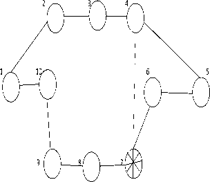
Fig.2a. Node 7 is Isolated Link 4-7 is Restricted
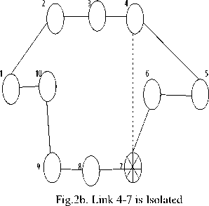
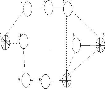
Fig.2c. Nodes 1,5,7 are Isolated Links 1-2,4-7,5-7 are Isolated Links 110,4-5,6-7 are Restricted to the backbone. By making use of the shortest path, every router, generates a forwarding table which is a configuration specific. This means that all the packets are forwarded, based on the respective forwarding table calculations which are configuration specific. A router does not immediately inform the rest of the network about its failure, to reach a neighbor through one of its interfaces. Instead the packets that were supposed to be sent through the failed interface are identified and specifically marked to belong to a particular backup configuration and another optional route is chosen to send the same towards its destination. This clarifies that all the routers which are down the path are aware of the configuration they have to use.The IP header’s DSCP field is used for packet marking. In case of no failure all the packets are forwarded as per the original configuration [13]. So in such circumstances, the failure free original routing, where the normal link weights are used, does not get affected by MRC. In order to obtain steady routing, the backup configurations in MRC must stick to the following requirements:
-
1. In a configuration if a particular node is isolated it cannot carry transit traffic. However, traffic should reach and depart from an isolated node.
-
2. When a link is isolated in a configuration, it should not carry any traffic.
-
3. A path has to connect all node pairs without passing through an isolated node or link, in every configuration.
-
4. Isolation, in one backup configuration is a must for every node and every link [4].
Weights on the restricted links is the first concern. In order that isolated node has no path going through it, it is important that the weight W of restricted link is at least the summation of all link weights w, in the original configuration that is W > ∑ w ij.
This is to guarantee that the shortest path algorithm chosen would allow a path between a node pair which does not pass through the isolated node. As no shorter path exists for packets to be sent to or received from the isolated node, therefore the packets will pass through the restricted link with weight W. The next requisite is that isolated links have an infinite weight, so that no traffic is routed through it. Also a backbone is a must for every configuration and at least one restricted link should connect every isolated node to the backbone. Depending on the set of backup configurations, a shortest path algorithm is used to generate forwarding tables. Every failed component is kept away from the forwarding tables. The detecting node, which is next to the link/node that has failed, is the one which will find the configuration where the failed component is isolated and is also responsible for forwarding packets as per the configuration. Every node has to have information, about which is the configuration, where its succeeding node is isolated. Also, the configuration where it is isolated itself, should also be known. When configurations are being generated all the nodes are given this information. Figure 3.is the flow diagram revealing the various steps that are followed in the forwarding process of a node.
When the packet arrives, it is forwarded on the normal route (Step1). Packets which are unaffected by failure are, normally forwarded, whileas the packets which are forwarded through a broken interface are dealt in the manner shown in (Step2). When packets are marked with a backup configuration identifier by another node they are to be discarded as shown in Step 3. When a point of failure is reached for the second time it could be either failure of exit node or multiple network element failure. In order to avoid configuration looping, packets can switch configuration just once [7]. In case multiple failures are to be taken care of, packets will have to switch to a configuration having a higher ID.
A next hop lookup in the configuration is made in which isolation of the neighbor is carried out. This is step 4. If the lookup does not return the same broken link, the packet is marked with the correct configuration identifier. The packet is then forwarded in this configuration in step 5. It is guaranteed that the packet will reach its exit node, and will not be routed through the point of failure again. The packet reaches a dead interface, a second time if the neighbor is the exit node and dead as well. If the lookup returns the dead link for the configuration where isolation of neighbor is carried out, it is understood that the exit node for the packet is the neighboring node. This is because the isolated node is never used to route packets. Step 6 calls for look up in the configuration where isolation of detecting node is done. It is known that a link is always isolated in the same configuration as one of the nodes to which it is attached, therefore it is not possible for the dead link to return from this lookup.
-
IV. Methodology
NS3 is an event driven simulator used for simulating wired and wireless networks. It is used to analyze events to have a better understanding of the behavior of networks. The topology as shown in Figure 4 has been used to study the performance of routing protocols OSPF, OSPF Rerouting 1, OSPF Rerouting 2 and MRC by varying packet sizes. NS3 simulator is used to analyze the behavior and performance of routing protocols OSPF and MRC. The flow monitor in NS3 is a few lines of code and it measures all flows in the simulation.
-
V. Result Analysis
The main focus in this paper, is on the effect of packet sizes on throughput, packet delivery ratio, packet loss and delay for various routing protocols like OSPF, OSPF Rerouting 1 (with 1 link breakage), OSPF Rerouting 2 (with 2 link breakages) and MRC as shown in Tables 1, 2, 3 and 4 respectively.
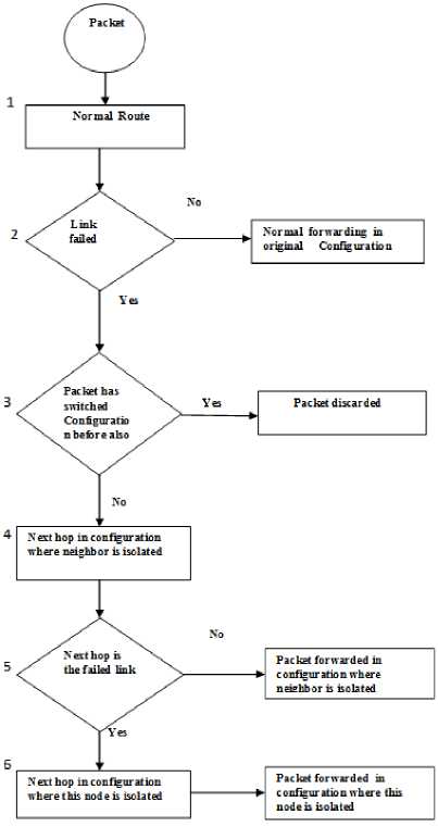
Fig.3. Forwarding of Packets by a Node
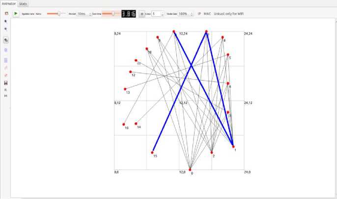
Fig.4. Topology Considered
Table 1. Throughput, PDR, Packet loss, Delay and Jitter values for OSPF Normal
|
PKT SIZE |
THROUGHPUT |
PACKETS SENT |
PACKETS RECEIVED |
PDR % |
PACKET LOSS |
TOTAL DELAY |
JITTER |
|
200 |
27780.4 |
15624 |
15596 |
99.82 |
28/0 |
0.00898938 |
0.00299646 |
|
400 |
26074.6 |
7812 |
7798 |
99.82 |
14/0 |
0.00899417 |
0.00299806 |
|
600 |
25502.7 |
5208 |
5198 |
99.83 |
10/0 |
0.00899781 |
0.00299927 |
|
800 |
25221.7 |
3906 |
3899 |
99.82 |
7/0 |
0.00900375 |
0.00300125 |
|
1000 |
25049.5 |
3124 |
3119 |
99.83 |
5/0 |
0.00901027 |
0.00300342 |
|
1200 |
24934.2 |
2604 |
2599 |
99.80 |
5/0 |
0.00901218 |
0.00300406 |
Table 2. Throughput, PDR, Packet loss, Delay and Jitter values for OSPF Rerouting1 (with 1 link breakage)
|
PKT SIZE |
THROUGHPUT |
PACKETS SENT |
PACKETS RECEIVED |
PDR % |
PACKET LOSS |
TOTAL DELAY |
JITTER |
|
200 |
22215.6 |
12523 |
12492 |
99.75 |
31/0 |
0.0119612 |
0.00398706 |
|
400 |
20850.1 |
6273 |
6257 |
99.74 |
16/0 |
0.0119504 |
0.00398347 |
|
600 |
20395.6 |
4190 |
4179 |
99.73 |
11/0 |
0.0119397 |
0.00397988 |
|
800 |
20168.3 |
3148 |
3140 |
99.74 |
8/0 |
0.0119308 |
0.00397693 |
|
1000 |
20027.1 |
2523 |
2516 |
99.72 |
7/0 |
0.0119184 |
0.00397281 |
|
1200 |
19941 |
2107 |
2101 |
99.71 |
6/0 |
0.0119078 |
0.00396925 |
Table 3. Throughput, PDR, Packet loss, Delay and Jitter values for OSPF Rerouting2 (with 2 link breakages)
|
PKT SIZE |
THROUGHPUT |
PACKETS SENT |
PACKETS RECEIVED |
PDR % |
PACKET LOSS |
TOTAL DELAY |
JITTER |
|
200 |
16658 |
9423 |
9392 |
99.67 |
31/0 |
0.0149076 |
0.00496919 |
|
400 |
15635.8 |
4735 |
4719 |
99.66 |
16/0 |
0.0148628 |
0.00495427 |
|
600 |
15293.4 |
3172 |
3161 |
99.65 |
11/0 |
0.0148183 |
0.00493943 |
|
800 |
15121.4 |
2391 |
2382 |
99.62 |
9/0 |
0.0147714 |
0.0049238 |
|
1000 |
15020 |
1923 |
1915 |
99.58 |
8/0 |
0.0147232 |
0.00490773 |
|
1200 |
14947.9 |
1610 |
1603 |
99.56 |
7/0 |
0.0146786 |
0.00489285 |
Table 4. Throughput, PDR, Packet loss, Delay and Jitter values for MRC
|
PKT SIZE |
THROUGHPUT |
PACKETS SENT |
PACKETS RECEIVED |
PDR % |
PACKET LOSS |
TOTAL DELAY |
JITTER |
|
200 |
28945.3 |
16250 |
16220 |
99.82 |
30/0 |
0.00898889 |
0.0029963 |
|
400 |
27168 |
8125 |
8110 |
99.82 |
15/0 |
0.00899368 |
0.00299789 |
|
600 |
26572.2 |
5416 |
5406 |
99.82 |
10/0 |
0.00899847 |
0.00299949 |
|
800 |
26276.1 |
4062 |
4055 |
99.82 |
7/0 |
0.00900437 |
0.00300146 |
|
1000 |
26101.6 |
3250 |
3244 |
99.82 |
6/0 |
0.00900806 |
0.00300269 |
|
1200 |
25979.9 |
2708 |
2703 |
99.82 |
5/0 |
0.00901285 |
0.00300428 |
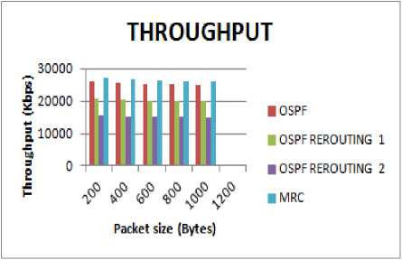
Fig.5. Packet size vs Throughput
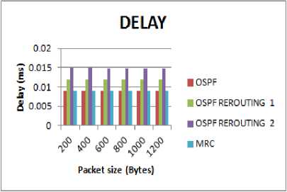
Fig.8. Packet size vs Delay
It is observed that, as the packet size increases, the number of packets sent and received automatically decreases in all the four configurations shown in Fig. 5. Further, throughput is highest in MRC followed by OSPF, then OSPF Rerouting 1 and the least value is for OSPF Rerouting 2. Packet loss in MRC is less than OSPF with one and two link breakages because backup paths are maintained, in advance in MRC.
PACKET LOSS
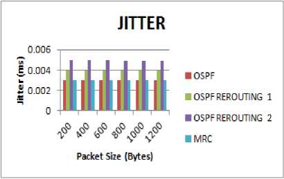
Fig.9. Packet size vs Jitter
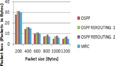
Fig.6. Packet size vs Packet Loss
Packet delivery ratio is higher in MRC as compared to OSPF with link breakages as is shown in Fig. 7. This is due to the larger number of packets being sent and received in MRC.
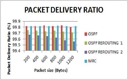
Fig.7. Packet size vs Packet Delivery Ratio
Also delay and jitter values are the least in MRC because of very fast recovery in case of link and node failures as compared to OSPF reconvergence time as shown in Fig. 8 and Fig. 9.
-
VI. Conclusion and Future Scope
Fast recovery in IP networks is achieved by MRC. The basis for the MRC is to provide all the routers with supplementary routing configurations, so that packets can be forwarded on backup routes to avoid failed network components [12]. Since backup configurations are calculated in advance, MRC operates very promptly after failure discovery. Following are the conclusions drawn
-
• The rules on the basis of which link weights are assigned, lays the foundation for packet forwarding modus operandi.
-
• Backup path lengths in MRC are quite near in value to optimal backup path lengths and are normally zero to two hops longer.
-
• Fast recovery is achieved by the MRC with little performance penalty.
Future work can be carried out in the ways listed below
-
1. Congestion that occurs after change in traffic pattern can be looked into and ways in terms of traffic engineering developed, to reduce it. This can be done by assigning intelligent link weights for every backup configuration.
-
2. Isolation of nodes and links for a single configuration is done in the MRC. It can be extended to multiple component failures.
-
3. Protection of multicast traffic from node failures is a challenging task. If a separate multicast tree could be maintained for each backup configuration, fast recovery is achievable from link and node failures.
References Analyzing Multiple Routing Configuration
- Aditithakkar, 2014, International Journal of Computer Science and Information Technologies,Vol.5 (6) , 8221-8224, Multiple Routing Configurations for Fast IP Network Recovery.
- Amund Kvalbein, Audun Fosselie Hansen, Tarik , Stein Gjessing and Olav Lysne, 2006, IEEE/ACM Trans. Networking, 17(2), 2006,pp. 473-486, Multiple Routing Configurations For Fast IP Network Recovery.
- B. Sasthiri and T Prakash, 2012,International Journal of Advanced Networking and Applications, Volume: 03, Issue: 04, pp 1292-1297, Multipath Routing Algorithms for Congestion Minimization.
- C. Filsfils, P. Francois, J. Evans, and O. Bonaventure,July 2005 , ACM SIGCOMM Computer Communication Rev., vol. 35, pp. 35–44, Achieving sub-second IGP convergence in IP networks.
- Gowtham Gajala, Nagavarapu Sateesh, April 2013, International Journal of Advanced Research in Computer and Communication Engineering, Vol. 2, Issue 4, Multiple Routing Configurations for Fast IP Network Recovery.
- L.Dev, January 2014, International Journal of Computer Science and Mobile Computing, Vol.3 Issue.1, pp.559-568, Fast IP Network Recovery Using MRC from Multiple Failures.
- M. Venkata Krishna Reddy, D. Jamuna Salil Saurabh, August 2012, International Journal of Computers & Distributed Systems, Volume 1, Issue 2, MRC Approach for Fast Link Failure Recovery in IP Network.
- Markopoulou, G. Iannaccone, S. Bhattacharyya, C.-N. Chuah, and C. Diot, March 2004, Proc. IEEE INFOCOM, March 2004, vol. 4, pp.2307–2317, Characterization of failures in an IP backbone network.
- Meeravali B.Bobby, Arun Kumar, N.Naveen Kumar, NakkaRaoKudaNageswaraRao, August 2013, International Journal of Engineering and computer science,Volume 2, Issue 8, pp 2628-2634, Multiple Routing Configurations For Fast Ip Network Recovery.
- Ohara, Imahori and Van, April 2009, Proceedings of IEEE, INFOCOMM conference, Brazil,pp 298-306, Maximum Alternative Routing Algorithm.
- P. Francois, M. Shand, and O. Bonaventure, May 2007, Proc. IEEE INFOCOM, Anchorage, AK, pp. 89–97, Disruption free topology reconfiguration in OSPF networks.
- Shand and Bryant, 2008, IETF Internet draft framework, IP fast reroute framework.
- Shrikantand Ghonge, 2014, International journal of Research in Advent Technology, Vol2, No. 4, A review of different approaches towards Multipath Routing Techniques.
- S. Nelakuditi, S. Lee, Y. Yu, Z.L. Zhang, and C.N. Chuah, April 2007, IEEE/ACM Trans.Networking, vol. 15, no. 2, pp. 359–372, Fast local rerouting for handling transient link failures.
- Srinivasan and Giridhar, 2009, Proceedings of IEEE/ACM transactions on Networking, Maintaining colored trees for disjoint Multipath Routing under node failures.
- T Anji Kumar and Dr M.H.M. Krishna Prasad, 2012, International Journal of Computer Networks and Information security (IJCNIS) Volume 3, Issue 4, Enhanced Multiple Routing Configurations For Fast IP Network Recovery From Multiple Failures.
- Tarik, Audun Fosselie Hansen, Amund Kvalbein, Matthias Hartman, Rudiger Martin, Michael Menth, Stein Gjessing and Olav Lysne, 2012 , ieeexplore.ieee.org , Network and Service Management, Relaxed Multiple Routing Configurations IP Fast Reroute for Single and Correlated Failures.
- Telhourani and Cho, Proceedings of IEEE International Conference on Communication, CapeTown,South Africa, pp 1-5, Resilient Multipath Routing with Independent Directed Acyclic Graphs.
- Vimal pal and Sneha Ramteke, 2014, ieeexplore.ieee.org, A framework for fast IP Rerouting.
- Suresh Kumar, Shelja Sharma, July 2015, International Journal of Computer Network and Information Security (IJCNIS), Vol. 7, No. 8, pp: 21-29, Experimental Analysis of OLSR and DSDV Protocols on NS-2.35 in Mobile Ad-Hoc Networks.
