Anchor bonds of the contact joint of steel-concrete structures

Author: Zamaliev Farit Sakhapovich, Tamrazyan Ashot Georgievich, Vatin Nikolai Ivanovich
Journal: Строительство уникальных зданий и сооружений @unistroy
Section: Строительные конструкции, здания и сооружения
Article in issue: 1 (115), 2025.
Free access
Ribbed slabs, consisting of metal rib beams and a reinforced concrete monolithic slab, are often used. Because of the joint work of the reinforced concrete slab and steel ribs, such floors are called steel-reinforced concrete. The main elements that provide the joint work of the layers of ribs and plates in them are anchor ties. The set of design solutions for anchor ties used in the contact joints of steel-reinforced concrete structures is multifaceted. A comparative analysis of the variants of the structures of anchor connections shows that rod anchor connections have an advance in the manufacturability of the connection and the material consumption. Unlike bridge structures, stud bolts are often used as inclined clamps from smooth round bars or corrugated vertical reinforcing bars welded to the upper shelf of a steel rib. An analysis of various experimental studies shows that the anchor ties work in bending and tension. The research object was the stress-strain state of anchor rods. The numerical and experimental studies of the work of the steel-concrete contact joint on prism models were carried out. The work diagrams for three types of anchors are given. Numerical studies revealed a mosaic of stresses and strains in anchors. Based on the analysis of numerical and full-scale experiments, analytical dependencies are proposed that reflect the actual operation of anchor ties. Comparisons of the calculation results by analytical formulas and comparisons with numerical and full-scale experiment data are given. Numerical studies have revealed the pattern of the stress-strain state of the contact joint, the stages of development of cracks in the concrete flange, and the sequence of development of deformations in anchor ties. It was revealed that vertical anchor rods have an increased bearing capacity, although displacements are 1.5-2 times greater than those of loop-shaped anchor ties.
Steel-reinforced concrete structures, Anchor connections, Anchor strength, Analytical dependencies
Short address: https://sciup.org/143184690
IDR: 143184690 | DOI: 10.4123/CUBS.115.4
Анкерные связи контактного стыка сталежелезобетонных конструкций
Ребристые плиты, состоящие из металлических ребристых балок и железобетонной монолитной плиты, часто применяются. Из-за совместной работы железобетонной плиты и стальных ребер такие перекрытия называются сталежелезобетонными. Основными элементами, обеспечивающими совместную работу слоев ребер и плит в них, являются анкерные связи. Совокупность конструктивных решений анкерных связей, используемых в контактных стыках сталежелезобетонных конструкций, многогранна. Сравнительный анализ вариантов конструкций анкерных соединений показывает, что стержневые анкерные соединения обладают преимуществом в технологичности соединения и материалоемкости. В отличие от мостовых конструкций, в качестве наклонных зажимов часто используют шпильки из гладких круглых прутков или гофрированных вертикальных арматурных стержней, приваренных к верхней полке стального ребра. Анализ различных экспериментальных исследований показывает, что анкерные связи работают на изгиб и растяжение. Объектом исследования являлось напряженно-деформированное состояние анкерных стержней. Проведены численные и экспериментальные исследования работы сталебетонного контактного соединения на призматических моделях. Приведены диаграммы работы для трех типов анкеров. Численные исследования выявили мозаику напряжений и деформаций в анкерах. На основе анализа численных и натурных экспериментов предложены аналитические зависимости, отражающие реальную работу анкерных связей. Приведены сопоставления результатов расчетов по аналитическим формулам и сравнения с данными численного и натурного эксперимента. Численные исследования выявили закономерность напряженно-деформированного состояния контактного соединения, стадии развития трещин в бетонном фланце и последовательность развития деформаций в анкерных связях. Выявлено, что вертикальные анкерные стержни обладают повышенной несущей способностью, хотя перемещения у них в 1,5-2 раза больше, чем у петлеобразных анкерных связей.
Text of the scientific article Anchor bonds of the contact joint of steel-concrete structures
In steel-concrete beams and slabs, which are structures of a composite section, one of the main issues is ensuring reliable joint operation of the layers provided by anchor ties [1]. A correct assessment of the bearing capacity of anchor ties makes it possible to design reliable and economical steel-reinforced concrete structures of a composite section consisting of two or more layers [2].
The steel-concrete composite beam with non-welded horizontal shear connectors subjected to static bending has been studied [3]. Test results show a behavior similar to steel-concrete composite beams with usual connectors. A flexural failure occurred with a plastic hinge in the mid-span crosssection, accompanied by the yielding of the steel girder and crushing of the concrete. Therefore, the connection did not fail during the test and efficiently allowed the transmission of shear forces from the slab to the girder.
A steel-concrete composite beam with shear studs was loaded under a monotonic bending moment until failure [4]. The concrete part of the beam was transversally cracked before the beginning of the test because of restrained shrinkage strains. The behavior of the beam was divided into an elastic domain and a plastic domain with significant ductility. The failure in the central zone originated in high compressive strain in the concrete part of the beam, followed by crushing. The transverse initial cracks induce, mainly in the elastic domain, strong discontinuities in the longitudinal distribution of the slip and Zamaliev, F.; Tamrazyan, A.; Vatin, N.
a noticeable evolution of the shear stud deflection scheme in the concrete slab. Numerical simulations performed within the elastic domain, accounting for slip or slip absence, agreed with measurements for deflection and longitudinal strains.
Numerical studies and comparisons with the results of experimental studies of steel-reinforced concrete beams with studs at the junction of layers are given in the source [5]. A steel-concrete beam was tested under cyclic loading and showed no fatigue damage after over 2 million cycles. The beam was then statically loaded up to failure. Its behavior within the elastic and plastic domain was very similar to that of the same beam previously subjected to static loading only. However, analytical expressions for estimating the strength of studs were not presented.
The outcomes of numerous experiments involving composite beams containing trapezoidal steel decking are showcased and complemented by the results of corresponding pushout tests [6]. A comprehensive examination of the shear connection's performance is undertaken, considering both meticulously executed pushout tests without applying supplementary lateral restraints and beam tests. This scrutiny revealed that the failure modes observed in both types of tests were congruent, the loadslip characteristics exhibited remarkable similarity, and the strengths of the connectors were comparable.
The articles [7], [8], studied the dynamic behavior of steel-concrete composite beams with differing shear connection systems. Two distinct blind bolt connectors were employed as shear connection systems within steel-concrete composite beams. A comprehensive Timoshenko beam model designed for steel-concrete composite beams was established and subsequently juxtaposed with the outcomes of practical experiments. Furthermore, an exploration was conducted using the Timoshenko beam model to scrutinize an uncertain boundary condition. As a result of this investigation, an empirical correlation was formulated, establishing a connection between the displacements observed at the beam supports and the rotation of the cross-sectional face. A finite element model was then developed. The nature of changes in dynamic behavior due to damage was investigated using the finite element model. It was found that at increased loading, the behavior of the cast-in and retrofitted connectors was fundamentally different due to the retrofitting procedure.
An in-depth exploration was conducted into the dynamic characteristics of steel-concrete composite beams that had undergone retrofitting with various bolted shear connectors [9]. An experimental investigation focused on cast-in versus retrofitted shear connectors to unveil the distinctions in their dynamic performance. This study involved identical steel-concrete composite beams equipped with diverse shear connection systems. The research encompassed using two types of blind bolt connectors as shear connection systems within the steel-concrete composite beams. Additionally, a welded shear stud specimen was examined in cast-in and retrofitted configurations for comprehensive analysis. Subsequently, a finite element model was meticulously crafted to facilitate a deeper understanding of the alterations in dynamic behavior associated with damage.
In 2018, the research of steel-concrete trussed beams with a steel joist with inclined rebars, which are welded to a smooth steel plate and then embedded within the concrete cast in situ, was reviewed [10]. The most relevant scientific contributions published up to 2018 regarding the experimental investigation of shear behavior were summarized and discussed. The codes and analytical models are reviewed.
The steel-concrete composite beams with the perfobond shear connectors (PSCs) were studied [11]. Ten one-sided pullout tests have been carried out to investigate the PSC's behavior and shear resistance. The results were compared against pullout test results from other researchers and the predictions offered by several shear resistance equations. It has been found that the one-sided pullout test results are consistent with the analytical predictions offered by these expressions compared to the previous research using pullout tests.
The article [12] studies a composite steel-concrete bridge floor featuring headed shear studs affixed to a flat steel plate. It is expected to combine thick steel plates with a relatively moderate layer of concrete in bridge construction. In some instances, particularly in wide slab applications, the optimal arrangement for the placement of shear studs may necessitate their welding on top of an existing butt weld between steel plates. An intriguing aspect of this scenario is our limited knowledge regarding the shear resistance at the weld-to-weld interface and its potential adverse effects on the system’s resistance overall. Additionally, the ultimate behavior of this system involves a combination of factors. It initially hinges on the flexural resistance of a composite cross-section. However, when the concrete experiences cracking, it transitions into developing a compressed arch anchored in the headed shear studs. This transition highlights the critical importance of these connections. The research paper delves into these critical inquiries and offers an exhaustive analysis of the system's behavior when it reaches its ultimate Zamaliev, F.; Tamrazyan, A.; Vatin, N.
limit state. The investigation includes two types of tests. The first category comprises pure shear tests that align with push-out tests, while the second category involves beam tests subject to four-point loading, where the shear spans bear longitudinal shear loads. In each pair of tests, a reference specimen is prepared. These specimens either lack a butt weld or include a butt weld directly beneath the line of shear studs. Notably, the study focuses on typical floor dimensions relevant to bridge applications.
The lockbolt demountable shear connector (LB-DSC) has been introduced [13]. This connector features a grout-filled steel tube securely embedded within a concrete slab and fastened to a partialthread bolt with geometric compatibility. The bolt is affixed to the top flange of a composite beam's steel section. It incorporates a conical seat lug that securely locks into a predrilled, counter-sunk hole in the steel section's flange, ensuring a slip-free connection between the bolt and the flange. The lockbolt demountable shear connector deconstruction is a straightforward process that involves disengaging the tube from the slab's top using a specially modified wrench. The pushout tests have demonstrated exceptional shear resistance and stiffness compared to alternative demountable shear connectors. The slip capacity results categorize the lockbolt demountable shear connector as a ductile shear connector, further enhancing its desirability in structural applications. A design equation has been developed based on a comprehensive analysis of numerical simulations and experimental findings, enabling the prediction of shear resistance for the lockbolt demountable shear connector.
The research [14] examined the load-bearing capacity of shear stud connectors. It entailed applying finite element analysis through ABAQUS software to replicate the force-deformation behavior of these shear studs. Push-out tests were conducted to validate the accuracy of the finite element model. The investigation was then extended through comprehensive parametric numerical studies, which aimed to scrutinize the force-deformation attributes of diverse shear stud configurations. As a result of these endeavors, a design equation was formulated employing linear regression techniques, using the insights gleaned from parametric studies. Notably, this derived equation exhibited a commendable degree of conformity with the empirical data obtained from the experimental assessments.
In the context of research [15], a novel and cutting-edge shear connector involving bolts for steelconcrete composite structures was introduced. A series of static push-off tests were conducted to evaluate its performance, considering various bolt dimensions, the constrained condition of reserved holes, and the dimensions of the slab holes. Subsequently, a finite element model was validated using experimental data. This model was further employed to explore the impact of concrete strength, bolt dimensions, yield strength, bolt pre-tension, and the length-to-diameter ratio of high-strength bolts on the shear connector's performance. Based on the insights from finite element simulations and test results, approximation formulas for assessing the shear resistance behavior were proposed.
The coconut shell concrete in steel-concrete-steel sandwich beams under flexure was studied [16]compared to conventional concrete. Two cases without and with shear studs were considered to interconnect the bottom tension and top compression plates. The effect of river sand replaced with quarry dust was also considered. Therefore, four mixes of conventional concrete, conventional concrete produced using quarry dust, coconut shell concrete, and coconut shell concrete produced using quarry dust were used. Three different steel plate thicknesses were considered (4 mm, 6 mm, and 8 mm). Twelve steel-concrete-steel specimens were tested to evaluate the flexural performance under two-point static loads. It was found that the moment carrying capacity of the steel-concrete-steel sandwich beams increased when the thickness of the steel plate increased. Using quarry dust to replace river sand augmented the strength of beams.
In [17], a three-dimensional finite element model was developed to investigate the performance of high-strength bolted shear connectors subjected to inverse push-off loading. The finite element model included material nonlinearities and the interactions among all components. The accuracy and reliability of the proposed finite element model were initially validated against the available push-off test results. A parametric study was carried out to determine the influence of the concrete strength, the diameter and tensile strength of the bolt, the clearance between the concrete slab and the bolt, and the bolt pretension on the shear performance of high strength bolted shear connectors. Design recommendations were proposed for estimating the shear load at the first slip and load-bearing resistance of high-strength bolted shear connectors.
Steel-concrete-steel sandwich panels were investigated with two thin high-strength steel plates and a moderately low-density and low-strength thick concrete core [18]. A stud-bolt connector was used to regulate its shear behavior in sandwich panels. The parameters under analysis were the bolts' diameter, the concrete core's thickness, and the bolts' spacing. Furthermore, the concrete core was manufactured with normal-strength concrete and steel fibers concrete. An approximation formula was proposed to determine the shear strength.
A multi-cavity steel-concrete composite beam was proposed [19]. This beam used an internal perforated steel plate to connect the concrete with the steel structure instead of shear connectors. Two beams with the angle of inner porous steel plate as 60° and 75° were tested. The finite element modeling was used to analyze the influence of concrete strength, steel strength, porosity, and the angle of internal porous steel plate on the mechanical properties of composite beams. The bearing capacity of the composite beam is positively correlated with the strength of concrete and steel while negatively correlated with the porosity and the angle of the internal porous steel plate.
The shear performance and failure mechanism of stud shear connectors in steel-fiber-reinforced-concrete composite beams were studied [20] compared to steel-normal-strength-concrete composite beams. The experimental results revealed that the stud shearing failure was the main failure mode of all push-out specimens. Compared to the steel-norma-strength-concrete specimens, the development of cracks in the steel fiber-reinforced cementitious composite beams was efficiently restrained due to high-strength steel fibers added to the normal concrete. The finite element model was developed and verified by push-out test results. The finite element analysis results indicated that the shear resistance of stud shear connectors was significantly improved with the increase in the concrete compressive strength, the stud diameter, and tensile strength. In contrast, the aspect ratio of studs had a small impact on the ultimate resistance of stud shear connectors. The empirical formulas were presented.
Steel lightweight aggregate-concrete composite beams with bolted shear connections were studied [21]compared to normal concrete composite beams. A three - dimensional numerical model we developed to study the shear properties of the bolt connections embedded in steel lightweight aggregate-concrete composite beams. Nonlinear geometric effects and material nonlinearities were considered. The accuracy and reliability of the finite element modeling were initially calibrated and validated against the push - off tests described in the literature. The basic shear properties of the bolted connection were studied. The effects of the concrete strength, concrete density, bolt diameter, and bolt tensile strength on the shear behavior of the bolt connections embedded in steel lightweight aggregate-concrete composite beams were also investigated. The design formulae were proposed.
The research paper [22] introduces a bolted nail and a combined connector designed to mitigate the impact of various factors on the mechanical performance of shear stress connectors. Through a series of experimental investigations, the study explores these connectors' shear resistance, failure mechanisms, and stress-strain characteristics. A comparative analysis between the bolt connectors and standard stud connectors reveals that stud connectors exhibited signs of deformation at 64% of the bolted connectors' ultimate capacity. In contrast, bolted connectors displayed deformation at 56% of their maximum capacity. The onset of connector cracking occurred when the included angle with the horizontal direction reached approximately 45° for bolted connectors and about 50° for stud connectors. Notably, stud connectors exhibited excellent shear resistance and ductility. Unlike bolted connectors, stud connectors demonstrated higher initial deformation bearing capacity and ultimate bearing capacity, surpassing the former by 27.68% and 12.07%, respectively. Furthermore, stud connectors exhibited superior ductility, deformation performance, and shear resistance. On the other hand, bolted connectors excelled in pull-out resistance.
A numerical model of the bearing-shear connector was developed and validated by push-out tests [23]. The stress of the bearing-shear connectors and concrete slab during loading and exploring the failure mechanism of bearing-shear connectors was analyzed. The shear plate's concrete strength, thickness, and tensile strength significantly influenced the shear behavior of bearing-shear connectors. According to the experiments and numerical analysis, calculation formulae for the ultimate shear resistance and slip modulus were proposed.
The study [24], [25]delved into the flexural and shear-bonding characteristics of the developed composite beams, drawing from experimental investigations and theoretical and analytical research. Seven flexural beams underwent testing involving the application of monotonic bending loads at two support points to elaborate on the methodology. In addition, four shear bonding beams were subjected to compressive loading procedures. The findings from the flexural tests unveiled a noteworthy trend wherein the flexural strength of the broader composite-steel beams exhibited an approximate 20% enhancement as the steel thickness increased by 3 mm, transitioning from 6 mm to 9 mm. In the context of shear-bonding tests, it was established that all specimens lacking shear connectors displayed inadequate shear-bonding strength to withstand the mechanical bonding mechanism. Consequently, it was suggested that such specimens necessitate reinforcement in the form of two or more flat bars. Zamaliev, F.; Tamrazyan, A.; Vatin, N.
The study [26]delved into the examination of precast steel-ultra-high-performance concrete (UHPC) composite beams that were equipped with high-strength friction-grip bolt (HSFGB) shear connectors. A finite element model was meticulously crafted, considering the inherent nonlinearities of materials and geometry. Through empirical validation, this model was confirmed for its accuracy and reliability. Subsequently, the research unveiled the intricate mechanisms governing the internal stress transfer processes of HSFGBs and elucidated the failure mechanism inherent in precast UHPC.
An analysis of articles devoted to assessing the strength of the contact joint of steel-reinforced concrete structures shows that they are mainly devoted to developing and experimental studies of various anchor connections. The bearing capacity of a contact joint is evaluated either based on the Eurocode or various computer programs using the finite element method, which cannot lead to reliable and economical solutions. The purpose of this article is to assess the strength of the most common types of anchor ties based on analytical dependencies, to achieve which the tasks of experimental and numerical studies are set, based on them, the formulation of formulas reflecting the actual stress-strain state of anchor rods.
-
2 Materials and Methods
Experimental and theoretical studies have revealed the stress-strain state of the contact seam in depth and width. Dependencies reflect the geometric parameters and strength properties of materials to determine the bearing capacity of vertical round anchors are as follows. The bearing capacity of concrete is determined by:
Prd = 0.24Idan pOR _ 2.5 < l / dan < 4,2
;
Prd = dl, JwR .I / dan > 4.2
;
where l / d an is means anchor length and diameter; R b is indicates the calculated concrete resistance.
The bearing capacity of the anchor could be determined in accordance to the material of the steel anchor rod1:
P = 0,063d2 у R (3)
an , an Y с y (3)
, where yc is the value of the coefficient of working conditions, Ry is the value estimated anchor resistance.
The bearing capacity of an inclined anchor made of round reinforcing steel or identical anchor branches in the form of an inclined yoke is proposed to be determined by the formula:
-
P an = 0.1 Aan Y c Ry cos « + dl J 10 Rb sin « (4)
,
Eurocode 2: Design of composite steel and concrete structures [28] proposes to consider the work of the anchor in tension by the expression
P rk = 0,8 Abf u (5)
, where fu is the limiting average resistance of the anchor to treatment.
Studies conducted at the Hong Kong Polytechnic University on models of steel-reinforced concrete samples with different stud bolts show the work of the latter in shear and tension both for samples with the application of shear forces perpendicular to the anchors (direct shear) and at an angle (combined shear) [8].
Steel-reinforced concrete prisms in a numerical experiment were modeled using the ANSYS software ( for samples with geometric parameters and loading according to the schemes corresponding to experimental studies. In a numerical experiment using a software package, calculations were performed in three stages: at the first stage, the finite element base of the prism sample was modeled; at the second stage, the loading conditions and physical and mechanical properties of the Zamaliev, F.; Tamrazyan, A.; Vatin, N.
model were recorded; at the third stage, the complex of equations was solved by the finite element method.
a)
b)
c)
d)
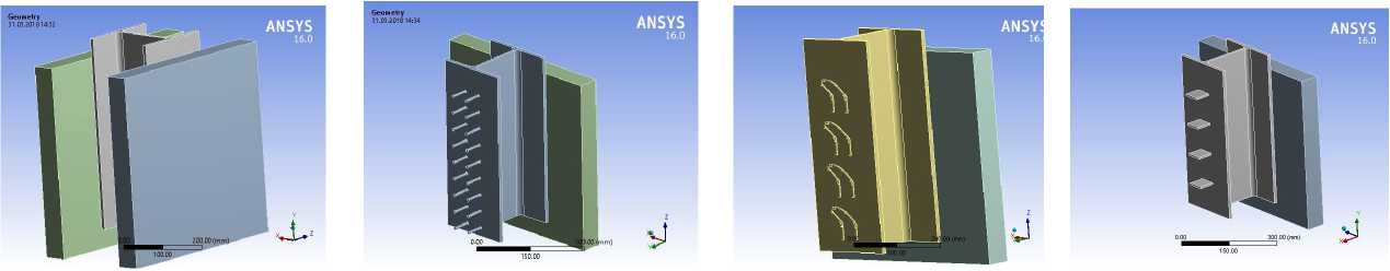
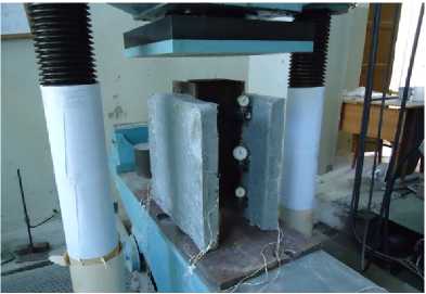
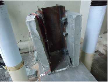
Fig. 1- General view of the prism model a); anchor from reinforcing bars b); anchor from loopshaped collars c); anchor from steel plates d)
The following types of samples are considered: a) prisms with anchors from vertical rods; b) samples with anchors from loop-shaped collars; c) models with anchors made of steel plates (fig 1).
Between the surface of the concrete slab (concrete class B30) and the surface of the steel belt of the I-beam (steel class C245), a Friction and contact with k-0.45 was specified. Rough gives the contact between the anchor rods and the concrete of the slab. This contact implies a possible separation of the surface and corresponds to an infinite coefficient of friction between the bonding bodies.
Next, the calculations were performed with the properties and conditions specified above, and a mosaic of stresses and strains was obtained.
Fig. 2 shows the stress pattern, and strains in anchor ties
of various type.
ANSYS
a)
b)
c)
Fig. 2 - Mosaic of stresses and strains in anchors: anchor from steel plates a): anchor from reinforcing bars b); anchor from loop-shaped collars c)
Models from prisms with a symmetrical arrangement of concrete slabs on the side of a steel I-beam's shelves and combined by anchors were subjected to numerical and natural studies. The materials of the steel I-beam and concrete slab, as well as anchor rods, were taken from the most used steel and concrete in steel-reinforced concrete floors. Welding anchor rods to the shelves of the I-beam embedment of concrete slabs was conducted in laboratory conditions. The dial gauges were used (Fig. 3a). The tests were carried out using an IPS-200 power press (Russia) to measure the shear of layers.
Experimental studies of reinforced concrete prisms and beams for static and repeated static loads [6] make it possible to establish the actual bearing capacity of the contact connection, as well as the nature of the formation and development of cracks in beams or ceilings, features of shear layers, the operation of anchors both in the elastic stage and beyond the elastic limit.
In experimental studies of prism models, to ensure the symmetry of the shift of the layers, mainly I-beams made of steel - C245 (Russia) were used. As anchors, angles, plates, loop-shaped clamps, and reinforcing bars from A500 (Russia) were used, and concrete of class B30 (Russia) was used in the slabs. The pitch of anchors varied f in beams from 150 to 300 mm [6].
a)
b)
The steel-reinforced concrete prisms were modeled in the numerical experiment using the ANSYS PC according to the scheme corresponding to the experimental studies. In the numerical experiment, the calculations were performed in three stages using the software package: at the first stage, the finite element model of the prism sample was modeled, at the second stage, the necessary loading conditions and physical and mechanical properties of the model were recorded, and at the third stage, a set of equations was solved using the finite element method.
Using the results of numerical studies, prism models were made for experimental studies. The following were used for the models: I-beam made of C245 steel, reinforcing bars and plates made of A500, concrete grade – B30. Samples were made with vertical bars, inclined loop-shaped “collars” and with steel plates with different pitches between them.
The prisms were tested in the laboratory of the Kazan State University of Architecture and Engineering (KSUAE), Russian Federation. The load was transmitted via the hydraulic system of the IPS-200 press. During the test, the deformations of the concrete flange and steel of the I-beam, as well as anchor ties, were measured using strain gauges glued to the surface of the concrete, beam and anchor. To protect against moisture, the strain gauges on the anchors, left in the body of the concrete, were protected with special compounds. The deformations on the concrete and steel were recorded by strain gauges with bases of 50 mm and 20 mm, respectively, through AID-4 with a switch magazine, the shift of the layers was measured by clock indicators I4 (Fig. 3a).
To check the operability of the test system, a trial test with a force of 0.5 tf was first carried out. After taking readings from all devices, i.e. after checking the system, the test was carried out by loading in steps of 1.5 t from the expected destructive load. At the steps, during the holding times, the readings were taken from the strain gauges, I4, i.e. the deformations of the concrete and steel, the displacements were recorded. The destructive load was recorded according to the readings of the test press scale at the moment of physical destruction of the sample. The load at which complete physical destruction of the samples occurred was taken as the limiting value of the load. The development of cracks in the body of the side plate was mainly observed before destruction. Destruction occurred due to the separation of the concrete plate from the steel I-beam. The general appearance and nature of the destruction of the prisms is shown in Fig. 3b
-
3 Resultsand Discussion
Based on the results of experimental studies conducted in the KSUAE laboratory, the stress and relative strain dependences for three types of anchors and at different pitch were processed and constructed, and the experimental results were compared, which are shown in the graphs in Fig. 8-14.
Fig. 4 shows the graphs of the relative dependences of stresses on load and relative deformations for three types of anchors. An analysis of the graphs of relative deformations for different anchors (Fig. 5b) shows the best performance of vertical anchors; that is, they have an increased bearing capacity than plates and loop anchors by 1.7 and 2.5 times, and the relative deformations of vertical anchors are four times greater than loop anchors, which shows better joint work with the slab without the appearance of fracture cracks in the concrete.
а)
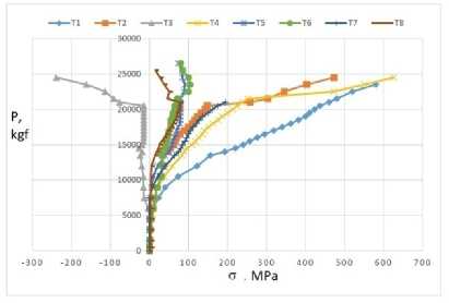
Fig. 4 - Dependences of stresses for vertical anchor rods a), relative deformations for three types of anchors b)
b)
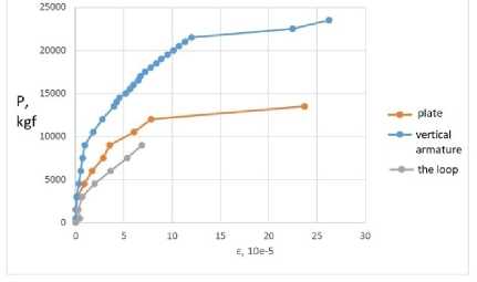
Fig. 5 shows the graphs of the vertical anchors' deformations dependences, depending on the pitch, and the graphs of relative deformations comparison for different anchor types. Dependence graphs
of vertical anchors for different pitches (50, 75, 100mm) show that anchors with a pitch of 50mm provide better joint work with concrete, and with an anchor pitch of 100mm, the bearing capacity of the sample is 2.33 times lower than the other two, and the deformability is five times more. A sample equipped with rod anchors with a pitch of 50 mm up to 240 kN works elastically and later in the plastic stage.
-
а) b)
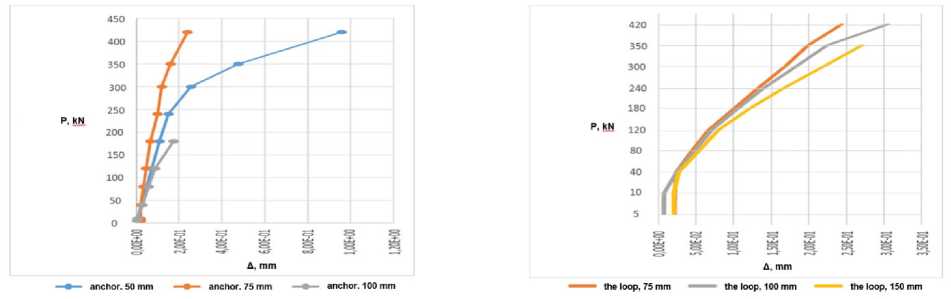
Fig.5 - Dependences of deformations for vertical anchors a), comparison of deformations for three types of anchors b)
Fig. 6 shows the load-stress graphs for those types of anchors and compares the results of numerical and natural experiments.
The following tasks are usually solved for contact weld designing and calculating:
- the shear forces arising in the contact seam of the bent structures are determined;
- the bearing capacity of the contact seam is determined.
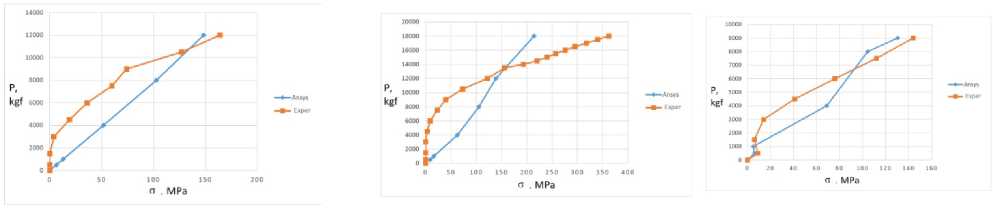
Fig.6 - Comparison of the results of numerical and natural experiments, "load-stress" graphs for different types of anchors
The presence in the structure of a composite steel-reinforced concrete structure of layers (reinforced concrete slabs and steel beams) with pronounced distinctive features in terms of physical and mechanical properties imposes increased requirements on anchor devices, on the one hand, reliable in terms of bearing capacity, on the other hand, technologically advanced in execution. At the stage of anchor ties choosing, their critical analysis is required from the standpoint of shear work and material efficiency. It is also necessary to find ways to evaluate the strength corresponding to their actual bearing capacity for operational loads.
At the layers junction - a reinforced concrete slab and a steel beam, the stress-strain state of the connection is very complex, connected on the one hand with crushing, and sometimes with chipping of concrete, and on the other hand, with bending of the steel anchor and its tensile work. The bearing capacity of the contact weld must be determined considering all factors, the operation of the weld elements, considering their actual stress-strain state.
Our experimental studies and those of other authors show that at the junction of layers - a reinforced concrete slab and a steel beam - there is a rather complex stress-strain state; in the limiting state, the slab collapses with cracks opening or concrete crushing, and the steel anchor experiences bending with tension. When analytically determining bearing capacity, all these factors must be considered.
The inclined anchor staple-like figurative bonds mainly work in tension, and the concrete at the contact experiences tension and shearing. Concrete spalling can be significantly reduced by rational placement and configuration of anchors. The case of anchor staple-like shaped inclined clamp and concrete in contact with it is the most significantly affecting the bearing capacity of the contact seam.
Assuming that the concrete is subjected to tension along the entire length of the anchor rod evenly, the magnitude of the shear force perceived by the concrete Tb has the form:
T b = ^ b ( ^b }nda cos a (6)
where a , l x , da are the angle of inclination, the length and diameter of the staple-like of the figurative anchor connection.
In case of destruction along concrete a b (£ b ) is equal to R b and in case of destruction along the anchor rod, the stresses in concrete are determined on the assumption that the concrete deformations are equal to the maximum elongation of the inclined anchor rod.
The value of the limiting shear force perceived by the anchor connection, assuming its work in tension, will be:
T s = ^ s (s . ) ^ p cos a ,
The main purpose of anchors in steel-reinforced concrete structures is to prevent the shear of layers - plates and steel beams. They must perceive the shear force T arising from the transverse forces in the bending element, which can be determined by the formula [8].
T = QS pl/ J red • a (8)
, where Q is the transverse force, Spl is the static moment of the plate relative to the neutral axis of the combined section, Jred is the moment of inertia of the reduced section, a - is the pitch of the anchors.
The connection strength of a concrete shelf with a steel beam is determined from the condition
T s 1\it, T uit, = min T b ; T s ) (9)
;
Experimental studies of steel concrete specimens with round vertical anchor rods have shown: depending on the anchor diameter and the magnitude of the shear force T, stress diagrams in the rod can be triangular (elastic work), rectangular (plastic work), mixed (elastic-plastic work) (Fig. 8). The stresses diagram in concrete along the length of the anchor rod has a curvilinear outline (Fig. 7), however, for the sake of simplicity of writing formulas in calculations, the calculation diagram of a rectangular or triangular outline is often taken.
Vertical anchor connection of steel-reinforced concrete flexural elements is subjected to bending and tension. Here the shear force is determined from the stress-strain state consideration of the slab with ribs. The shear force was found in a vertical anchor rod by considering it as a cantilever [27].
The vertical anchor rod was considered in the form of a cantilever, so the shear force is:
T . = M ./ l . (10)
,
The tensile force in the anchor rod is determined from:
Na = Ts /Si n a (11)
From the equilibrium condition of moments from external and internal forces, considering the stress diagram in concrete as an external component for a vertical anchor was obtained:
a) for triangular stress diagrams of concrete and anchor rod (Fig. 8) [8].
T . = 3/8
a s ( s . ) А . a
l x
d s n
,
where n is the number of anchor rods in the considered section, a is the plot completeness factor.
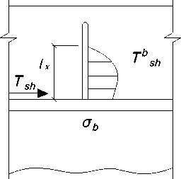
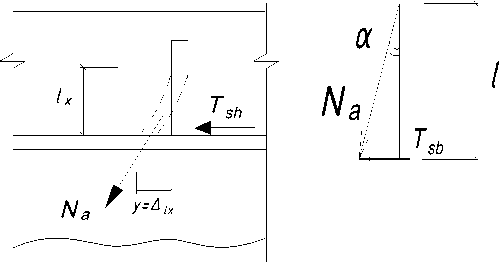
Fig.7 - Concrete stresses along the tie rod, tie rod deflection and force diagram
-
a) for a triangular diagram of concrete and a rectangular diagram of stresses in the anchor
T s = 3/4 £ j j s b d s n l
-
b) for rectangular stress diagrams of concrete and anchor rod
T s = 12 £ s k k £ d s n l x
-
c) for a curvilinear diagram of concrete and a rectangular diagram of anchor stresses
T s = 14
Q s (jS s ) A s a
y ( l x )
d s n
,
y ( lx ) is the distance to the center of the plot.
Obviously, under the joint action of M and N , the plasticity hinge formation will occur at lower values of forces than when they are considered as separate actions.
Obviously, under the joint action of M and N , the plasticity hinge formation will occur at lower values of forces than in considering M and N as separate actions.
With a gradual increase in the external force ( M and N ), the stress diagrams in the anchor section, passing through the stages shown in Fig. 8, the limiting diagram with a plasticity hinge is reached, shifted relative to the axis of the anchor rod In this case, it can be assumed that the moment is perceived by an internal pair of forces formed from equal areas of the compressed and stress diagram stretched zones, and the longitudinal force - the middle, symmetrical part of the stress diagram, marked.
Based on the condition of the joint action of M and N, the value of the limiting moment of the tensile-bent rod of the round-section anchor are as follows:
M lNm = F i d = ^ T A seg i d = Q ^ i L- tf J d. I d = Q r ^L d 2 £ ( ] - ^ ) 4 4 ,
where А seg
neb ~ ГГ1 Г"2 1 Гл 2 2
—; c = 2.^2br - о ; b = r - — 44r - c2 ;
A seg is the areas of segment.
a) b) c) d) e) f)
Fig.8 - Stress diagrams of anchor rods working in bending and bending with tension a) elastic, b) elastic-plastic, c) plastic work, d) elastic, e) elastic-plastic, f) plastic work
The limiting longitudinal force of a tensile-bent anchor of a circular cross section is written in the form:
N I M r T dd / 4[ d - 2 с ( 1 - ^ ) ] d - 2 c ( 1 - ^ ) 1 2 c
---=----------Г7-------=-----------= 1--
NT rTnd /4 dd p = M = M. = 5/4,c ■■'
WplrT dd гтd where ^d is the relative distance of the neutral line from the edge of the anchor section.
The equation of the boundary curve that determines the destruction area (achievement of the plasticity hinge) from the area of anchor rod safe operation under the simultaneous action of M and N .
v 2 + ^ = 1; or
М 2
V N T J
+
M
n lim
V M T J
= 1
The formula checks the strength of the vertical anchor rod:
( N } M ---- +-----
< 1
V ARan J W pl R an
When the concrete slab is shifted relative to the upper chord of the steel beam, the anchor rod bends in the concrete mass, and due to significant displacements of the layers, the anchor rod stretches (Fig. 7). Many researchers [7] note the head detachment of a stud bolt under extreme loads. According to the requirements of the design standards for steel and reinforced concrete structures, the calculation of rods subjected to bending with tension is carried out considering the bending moment and tensile forces, according to well-known formulas, considering tensile forces and bending moment.
4 Conclusions
-
1. The stress-strain state strength assessment for methods anchor ties of steel-reinforced concrete structures are analyzed.
-
2. Calculations were made on the ANSYS PC for steel-reinforced concrete prisms, which made
-
3. The features of the stress-strain state of steel-reinforced concrete samples with different anchor ties for static loads were studied, which showed:
it possible to reveal the stress-strain state pattern of the contact joint, the stages of cracks, the development of plastic deformations in the concrete flange and in anchor ties.
-
- in vertical rod anchors, the onset of plastic deformation corresponds to loads twice as high as in lamellar anchors, which can be explained by the better joint work steel-concrete in these samples;
-
- the largest movements for prisms with vertical anchors than for samples with plate anchors (less than 1.5 times) and with loop-shaped anchors (less than two times);
-
- the destruction of concrete slabs occurs mainly along the cut line by anchor devices, and destruction begins from the formation of cracks from the separation of the contact and from the development of the plastic deformation in anchor connections;
-
- the bearing capacity of prisms with vertical anchor rods is 37% and 49% higher, respectively, than prisms with loop and plate anchors.
-
4. Field tests showed:
The numerical calculations carried out according to domestic standards SP266.1325800.2016 show that the bearing capacity of the contact seam with anchor ties is 18-23% less than the experimental data.
-
- in plate anchors, plastic deformations began when the load reached 12 tf, and in vertical anchors -22.5 tf;
-
- the largest displacements were obtained: for prisms with looped anchors - 1.5 mm, for prisms with plates 2.2 mm, for prisms with vertical anchors - 2.849 mm;
-
- the concrete slab destruction of prisms occurs from the contact separation, mainly along the cut line by anchor devices and from the development of the plastic deformation in anchor ties;
-
5. The results comparison of a numerical experiment with the data of full-scale experiments shows the discrepancy between the results:
-
- up to 18% for voltages;
-
- up to 10% for movements;
-
- 15-21% for bearing capacity.
-
6. Based on the analysis of numerical and full-scale experiments, analytical dependencies are
proposed to assess the contact strength between the slab and the beam, considering the tensile and bending forces.
