Application of «gradient» algorithm to modeling thermal pipeline networks with pumping stations

Author: Lipovka Alex Y., Lipovka Yuri L.
Journal: Журнал Сибирского федерального университета. Серия: Техника и технологии @technologies-sfu
Article in issue: 1 т.6, 2013.
Free access
The paper deals with the analysis of flow distribution in regulated pipeline systems. Proposed inclusion of nodal elevations and piezometric heads into «global gradient» system of equations allows estimation of hydraulic regimes of thermal networks with pump stations, flow- and pressure-control valves during the process of iterative approach. Application of proposed modification of the Todini’s GGA method to calculation of flow distribution is shown on example of a small thermal network with pumps.
Water distribution network, flow equations, pumping station, heating networks, gga
Short address: https://sciup.org/146114715
IDR: 146114715 | UDC: 697.34.001.24
Использование «градиентного» алгоритма применительно к моделированию тепловых сетей с насосными подстанциями
В статье рассмотрены вопросы анализа потокораспределения в регулируемых трубопроводных системах. Предложено в систему уравнений метода «глобального градиента» ввести отметки рельефа местности и пьезометрические напоры, что позволяет в процессе итеративного приближения оценивать гидравлические режимы тепловых сетей с насосными подстанциями, регуляторами расхода и давления. На примере небольшой тепловой сети показана схема применения предлагаемой модификации метода Тодини к расчету потокораспределения.
Text of the scientific article Application of «gradient» algorithm to modeling thermal pipeline networks with pumping stations
The equations describing the flow in complex looped heating networks are nonlinear, the problem of their effective solution still remains open, despite of the already proven methods of solution, the most famous of which are: the Hardy Cross method of single loop balancing, generalized methods of loop flows (Qequations) and nodal pressures (Hequations) by В. Хасилев А. Меренков [1] and, of course, the «global gradient» algorithm (GGA) by E. Todini [2], which combines a fast convergence of the Qequations method with simplicity of Hequations.
Illustration of the sequence of iterations for the Qequations and GGA (QHequations) with two-stage algorithm solving first for the nodal pressures and then for flows sequentially in an iterative process provided by A. Simpson [3], in which a simple reference network with two tanks, two pipes and one node used to express equations and solutions based on these two methods.
Authors propose a lite modification of the method [2] and illustrate its application by calculating water distribution for a simple thermal network with various pumping stations.
Statement of the problem
The well-known one-dimensional mathematical model of steady isothermal flow distribution in hydraulic networks is described by three equations.
The first equation – the known law of hydraulic resistance of any link in the network
Alex Y. Lipovka and Yuri L. Lipovka. Application of «Gradient» Algorithm to Modeling Thermal Pipeline Networks… _
ДН , + ДН рт . — S t Q i i — 1, ... ,n, (1)
where A H i - value of pressure drop at the link , m; ^H pm . - pressure gain created by the pumping unit, m. For passive branches kH pm . = 0; Q i - flow at the link, m3/s; S i - hydraulic resistance of link i , s2/m5; n – number of links in network; r – exponent of the flow in the head loss equation.
The second – continuity of flow at each node
^Q i Q nd j ] 1, ™,m, (2)
where / Qt - algebraic sum of flows in the links, having a common node j, m3/s; Qnd. - outflow from i the node j, m3/s. If the node is a simple splitter (tees, crosses), than Qn^. = 0; if the node j is consumer (water outflow), than Qndj > 0; if the node is source (water inflow), than Qndj < 0; m - the number of nodes with unknown parameters.
And the third – there are equations that require the total pressure loss of zero within any loop in a network, consisting of independent loops
I
ДР, = 0
c = 1,...,k.
Solving system of equations (1)(3) gives us the flow distribution in a network (heads at the nodes and flows in the links). The difference in the use of a particular method is the time to achieve results with the required accuracy and specified number of iterations. For such complex hydraulic networks, like thermal supplying networks, it is very important, especially if you need to calculate accidents in real time.
Mathematical model
Formulation of GGA (Todini-Pilati Q-H equations) uses the generic term head H , without reference to the terrain, which requires additional computation to find piezometric heads
SQ |Q | «-1 + H j - H i = 0, (4)
where Hi , Hj – heads, respectively, at the beginning and end of the of the pipeline, m; n – the exponent in the head-loss equation for the link.
We propose to replace heads in the original formula (4) with the dependency that takes into account elevations and piezometric heads at the nodes эде|И+(^)-«+ад = о (5)
where Z i , Z j – elevations of nodes, respectively, at the beginning and end of the pipe, m; P i , P j – piezometric heads, respectively, at the beginning and end of the accounting section of the pipeline, m.
The energy conservation law in case of the pumping station:
^-“(3)
+ LPj + Z?) - (Pi + Zi) = 0-
where ω – the relative speed of the pump; h 0 , a , b – coefficients and the exponent of the approximation curve of pump characteristics.
Matrix form of the system of equations of the modified «global gradient» method:
G -Al [Ql _ [A0(P0 + Zo) + AZ + H opml =
-AT 0JLpJ I Qo J where G – square diagonal matrix of coefficients; Q0, Q – vector of given outflows in nodes and the unknown flows in pipes; P0, P – vectors of given and unknown piezometric heads; Z0, Z – vectors of elevations, respectively, for nodes with given and unknown piezometric heads; A0, A – incidence matrix, respectively, for nodes with given and unknown piezometric heads; H0pm – vector of products h0ω2 of coefficient from pump curve and its relative speed.
This nonlinear system of equations, solved by Newton’s method has the form:
к^,^.^
where J ( Q (k), P (k)) – Jacobian matrix; f ( Q (k), P (k)) – vector of deviations; (k), (k+1) – number of iteration; δ Q (k+1) – unknown vector of increments of volume flows, m3/s; δ P (k+1) – unknown vector of the increments of piezometric heads, m.
System of linear equations (8) can be written as
[G'* -^1 [Q (™) ■ Q» )] _ [G(k)Q(k)-A i (P(k) + Z)"A 2 (P o + Z o )-H opml
1 "A °llp■pJ-"1 -"-Qo
After transformations, we obtain the solution: a (k+1) iteration vector of the piezometric heads, obtained solely on the basis of previous (k) iteration of flows
^.w^,^^^
and (k+1) iteration vector of flows, which depends on the previous (k) iteration of flows, and (k+1) iteration of piezometric heads
Q(k+1) = G'"1(A1P(k+1) + E + (G' - G)Q(k)), where E – auxiliary vector of known variables
E = AiZ + A2(P0 + Z0) + H0pm
Creating and updating square diagonal matrices G , G' и G' -1 during the solution is very simple.
For pipeline corresponding entries G(i , i ) и G '(i , i ) are given as:
G(i,i) = r.lQil
G'(i, 0 = 2G(i, 0(14)
Corresponding entries G(i , i ) и G ' (i , i ) for pumps:
G(i,i) = a^2-b|Q|b-1
G'(i,i) = bG(i,i)
The inverse matrix G ' "* ( i , i ) is easily calculated by the formula
1 »«-№ (17)
An example of using the modified algorithm
Let us analyze the convergence of the proposed modified algorithm GGA on example of a simple thermal pipeline network with pumping stations (Fig. 1).
The results of calculation of flow distribution: piezometric heads at the nodes, flows in the pipes and operating points in pumping systems are given in Tables 1–3.
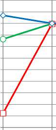
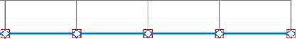
Relative deviations at each step of the iterative process for the flows are shown in Fig. 2, for piezometric heads – in Fig. 3, for head gains in pumps – in Fig. 4.
Diagram of infinite norm of vector of increments for piezometric heads is shown in Fig. 5.
Analysis of the calculations shows that piezometric heads are close to solution even after the first iteration, and after the fourth iteration the unknown parameters of the flow distribution are almost stabilized.
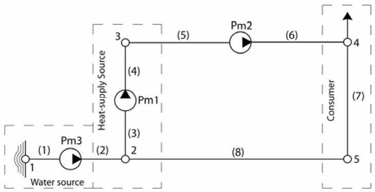
Fig. 1. The scheme of thermal network: Pm1, Pm2, Pm3 – circulating, pressure rising, water supplying pumping stations; 1–5 – numbers of network nodes; (1)–(8) – numbers of network pipes
Table 1. Piezometric heads in the network nodes at each iteration, P m
|
Number of iteration |
Nodes |
|||
|
2 |
3 |
4 |
5 |
|
|
1 |
45,275464 |
62,135573 |
38,83471 |
15,321225 |
|
2 |
44,994661 |
61,982059 |
38,969458 |
15,041589 |
|
3 |
44,994661 |
61,983504 |
38,97235 |
15,041677 |
|
4 |
44,994661 |
61,983502 |
38,972342 |
15,041680 |
|
5 |
44,994661 |
61,983502 |
38,972342 |
15,041680 |
Table 2. Volume flows in pipes of the network at each iteration, Q , m3/s
|
Number of |
Plots |
|||||||
|
iteration |
1 |
2 |
3 |
4 |
5 |
6 |
7 |
8 |
|
1 |
0,002778 |
0,002778 |
0,015686 |
0,015686 |
0,015686 |
0,015686 |
0,012908 |
0,012908 |
|
2 |
0,002778 |
0,002778 |
0,014905 |
0,014905 |
0,014905 |
0,014905 |
0,012127 |
0,012127 |
|
3 |
0,002778 |
0,002778 |
0,014881 |
0,014881 |
0,014881 |
0,014881 |
0,012103 |
0,012103 |
|
4 |
0,002778 |
0,002778 |
0,014881 |
0,014881 |
0,014881 |
0,014881 |
0,012103 |
0,012103 |
|
5 |
0,002778 |
0,002778 |
0,014881 |
0,014881 |
0,014881 |
0,014881 |
0,012103 |
0,012103 |
Table 3. Volumetric flows through pump, Q , m3/s and piezometric heads at the suction and discharge nozzles, P in , P out , m at each iteration
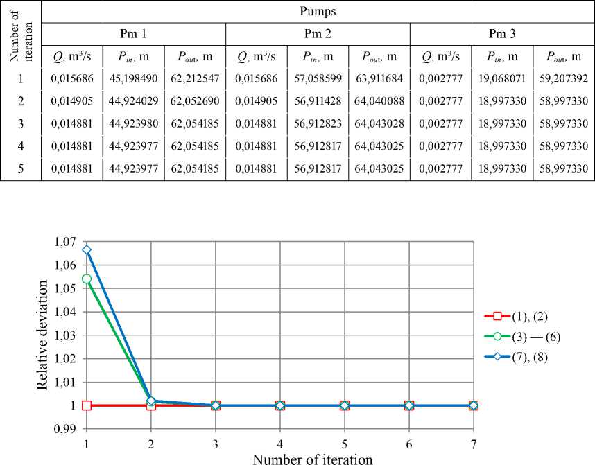
Fig. 2. Relative deviations of flows in pipes (1) – (8)
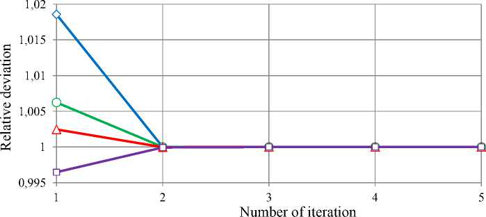
Fig. 3. Relative deviations of piezometric heads in nodes 15
1,01 1,005
0,995
0,99 0,985
0,98 0,975
0,97 0,965
0,96
0,955
Pm1
Pm2
Pm3
Number of iteration
Fig. 4. Relative deviations of head gains developed by the pumps Pm1–Pm3
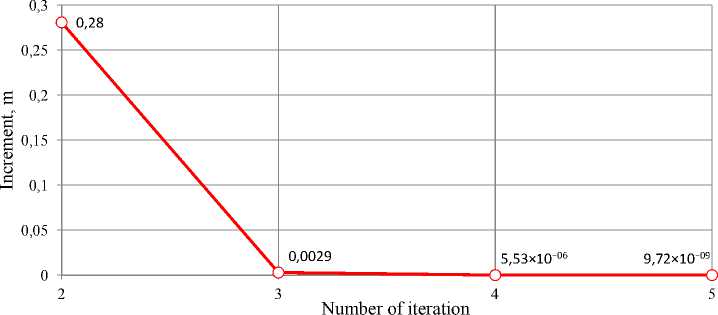
Fig. 5 Infinite norm of piezometric heads increments
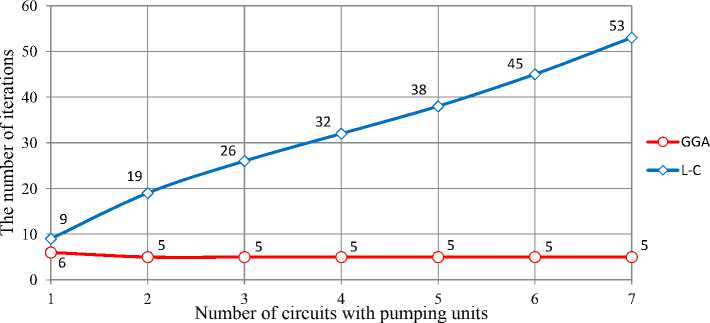
Fig. 6 Comparison of the convergence of the calculation: Hardy Cross method (L-C) and modified global gradient method (GGA)
Comparison of the convergence of the classical Hardy Cross method and the modified method of «global gradient» on a series of networks with pumping units in each independent loop was carried out, the results of which are shown in Fig. 6.
Conclusion
The modified algorithm, involving the introduction of piezometric heads and elevations directly into the equations of “gradient” algorithm, inherits high convergence of original GGA and provides ability control flow distribution and evaluate the reliability and sustainability of newly designed or existing thermal networks during the process of iterative calculation.
Proposed modification greatly increases the possibility of modeling pumping stations with both parallel and series layout of pumps with different characteristics, including frequency controllers. It also makes possible for fast tracking of operational point reposition for single pumps or whole pump stations due to changes in resistance characteristics of the thermal network, which may go beyond the optimum pump performance, and hence reduce its efficiency.
Research of high interest in this area is related to regulated pipeline systems with various flow and pressure control valves, which will be investigated further using authors’ computer program.
