Application of the computer vision system reconstructing the three-dimensional form of space technology objects

Author: Koshelev P.E., Yuev A.A., Konoplev Yu.V., Tolmachev A.S., Tishkov A.I.
Journal: Siberian Aerospace Journal @vestnik-sibsau-en
Section: Informatics, computer technology and management
Article in issue: 1 vol.23, 2022.
Free access
Trends in the development of the spacecraft (SC) industry pose increasingly complex problems for mechatronic systems. Due to the complexity of the assembly processes of large-sized transformable struc-tures (LTC) and solar panels, the current methods of structures deployment are becoming less reliable and relevant. In addition, the development of orbital stations leads to the emergence of a whole range of new problems. Using mechatronic manipulators is one of the promising approaches. However, the functionality of their application is severely limited by the algorithms for moving the effector and manipulating objects predetermined during development. In this regard, there is a need to develop new approaches to finding and determining the shape of the target object, for further calculation of the algorithm for its interaction with the mechatronic manipulator gripper. The paper presents a method for reconstructing the three-dimensional shape of objects, based on using a computer vision system. A stereo camera is used to obtain the spatial characteristics of the scene. Based on the data obtained, the scene is divided into several independent geometric surfaces, followed by stage-by-stage processing by neural network algorithms. The required parameters of the target objects are ex-tracted at each stage of the algorithm. YOLACT EDGE is used as a neural network architecture, which performs semantic segmentation and classification of objects. The correlation of the spatial characteristics of the target objects and the replacing three-dimensional model can be considered as a separate problem. To ensure this correlation, the neural network architecture was supplemented with the branch "Keypoints mask", which provides a prediction of the positions of the keypoints of objects that unambiguously deter-mine the spatial characteristics of the target object. As a result, the system obtained is able to provide the construction of a three-dimensional map of the swept area in real time. In addition, based on the received telemetric information, it is possible to calculate the trajectory of the manipulator's effector and its interaction with objects.
Computer vision system, machine learning, stereo vision, objects detection
Short address: https://sciup.org/148329603
IDR: 148329603 | UDC: 004.032.26 | DOI: 10.31772/2712-8970-2022-23-1-8-20
Text of the scientific article Application of the computer vision system reconstructing the three-dimensional form of space technology objects
At present, robotic manipulators are increasingly used in space industry to perform auxiliary work on the repair, transportation and maintenance of space station modules. A striking example is the mobile service system used on the ISS which performs functions mentioned in [1]. It consists of manually operated manipulators Canadarm-2 and Dextre. On the other hand, in the field of promising projects, the emphasis is increasingly shifting to autonomous robotic service, interpreted in a broad sense and also implying robotic assembly operations in relation to a very wide class of objects, including those not initially adapted for such service. At the same time, the proposed autonomous robotic means, being significantly more complex than the devices currently used in orbit, not only have no analogues in operation, but are also aimed at a reliable solution of very complicated complex problems [2].
A significant limitation in the operation of current autonomous mechatronic devices is that their operation is strictly limited by the algorithms for moving and manipulating objects that are predetermined during development [3]. Such restrictions do not allow achieving autonomy and flexibility of functional application, and also leave the need to restructure existing control algorithms when operating conditions and tasks change.
In this regard, there is a need to develop new approaches to finding and determining the shape of the target object, for further calculation of the algorithm for optimal interaction with the gripper of the mechatronic manipulator. One of the promising approaches is the use of a computer vision system based on artificial neural networks using a stereo camera [4].
The proposed approach involves processing the incoming video stream with subsequent detection and reconstruction of the three-dimensional shape of the desired objects, obtaining information about their position in space relative to the manipulator, as well as determining keypoints on object models for further generation of the algorithm for moving the effector and capture of objects by the manipulator [5].
1. Approaches and methods used
At the current moment several promising solutions have been proposed in the field of solving the problem of reconstructing a three-dimensional map of the surrounding space. However, each of them is based on established approaches, only working through and improving them using new technologies. Such an approach makes it possible to improve the quality indicators and speed of reconstruction, but it does not solve the problem globally.
The method proposed in the paper [6] solves several problems at once, that is, the segmentation and classification of objects, as well as the reconstruction of a three-dimensional scene in the presence of non-static objects (changing their position) on it. Spatial characteristics are read through the operation of the stereo camera. On their basis the system divides the scene into several surfaces using convolutional neural networks. The resulting surfaces are processed using static or non-static ICP methods and reconstructed using incremental depth map fusion. The proposed system shows good results in the conditions of reconstruction of non-static scenes. However, the resulting 3D map has noise, as well as empty zones, since only the surface of objects visible by the stereo camera is reconstructed with the help of filling with voxels.
The second noteworthy project is [7]. The authors developed a mobile robot-manipulator equipped with a 2D camera and a stereo camera. The resulting system is designed to implement an autonomous process for the production of small products on several machines remote from each other. A key feature is the use of the PointVoxel-RCNN neural network [8], based on the detection of objects on a depth map from a stereo camera. In addition to detection and classification, the neural network is also able to restore the three-dimensional shape of objects by selecting the most suitable parallelepiped in terms of dimensions. The disadvantages of the proposed approach are rather high complexity of preparing a data set and training the network (since it is based on a cloud of three-dimensional points), as well as the low accuracy of reconstructing the three-dimensional shape of objects.
2. The proposed method for the reconstruction of a three-dimensional map
Thе paper presents a more advanced approach that allows reconstructing a three-dimensional map of the swept area for a robotic system. The resulting map contains authentically recreated threedimensional models of target objects with the preservation of dimensional indicators, as well as ob-jects-obstacles. The method presented in the paper breaks the scene into several independent geometric surfaces, followed by a phased processing by neural network algorithms to extract the required parameters of the target objects. Figure 1 shows a generalized scheme of the algorithm for reconstructing a scene from a video stream, which can be “semantically” divided into 5 stages of processing.
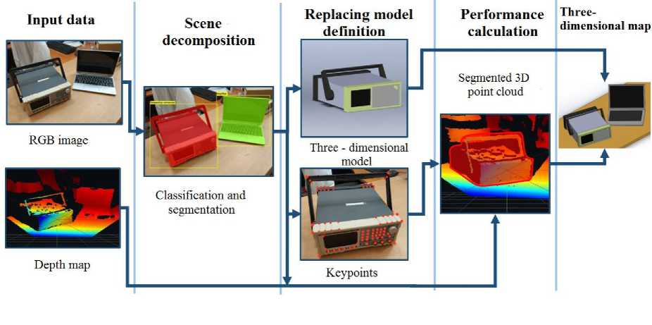
Fig. 1. The scheme of the proposed method of the three-dimensional map reconstruction
Рис. 1. Схема предлагаемого метода реконструкции трёхмерной карты
1. Obtaining spatial and "color" scene data in the form of two independent layers: an RGB video stream and a depth map.
2. Scene decomposition into target objects and background surface.
3. Definition of a replacing three-dimensional model and spatial characteristics of the target objects.
4. Calculation of the characteristics of the replacing model.
5. Combining the obtained data into a single three-dimensional scene.
2.1. Obtaining scene characteristics
2.2. Scene decomposition
2.3. Defining a replacing model
The problem of determining the spatial characteristics of the manipulator swept area is solved by using a stereo camera [9]. Such devices consist of a pair of cameras equidistant from the central optical axis, which makes it possible to obtain a cloud of three-dimensional points based on the triangulation apparatus. The resulting cloud is an array of values and contains the distance for each pixel from the camera to visible objects. However, the method under consideration also contains problems associated with uneven distribution and structural ambiguity between targets and background. To solve them it is proposed to use an additional method for determining target objects by RGB video stream from the stereo camera module.
One of the effective solution methods is the use of convolutional neural networks, which allow classifying and segmenting the contours of objects on an RGB video stream. The neural network is trained to the required level of error function minimization on a manually prepared set of images with already classified and segmented objects [10]. The presented method was chosen based on the fact that, in comparison with other object detection algorithms, it has several important advantages [11]. The first one is a fairly high robustness to changes in operating conditions, such as scaling, shift, deformation and partial overlap of objects, as well as changes in the level of illumination. The second advantage is the high accuracy of classification and segmentation of objects if the neural network is trained correctly.
At the moment, many different architectures of neural networks have been developed, each of which has its own advantages and disadvantages. However, the range of choice is very limited, since the specifics of the operating conditions should be taken into account. The execution of the task of manipulator control requires a sufficiently high speed of information processing from the system, and the application in the space field imposes significant restrictions on the weight and size indicators of the hardware.
The greatest progress in the field of processing speed was achieved in the YOLACT architecture [12]. It splits the instance segmentation into two parallel tasks. The first task uses convolutional networks to generate a set of prototype masks of the same size for each image, and the output uses the ReLU function for non-linearization. The second task is anchor-based object detection. It contains three branches: the first branch is used to predict the mask coefficients for each prototype, the second one is used to predict the validity of instance categories, and the third one is used to predict the coordinates of the bounding box.
However, the YOLACT network requires a sufficiently high computing power, which affects the need to use expensive hardware. Therefore, it is proposed to use a modified YOLACT EDGE architecture capable of processing (classifying and segmenting) up to 80 types of objects in 2D images on small peripheral devices (for example, Jetson AGX Xavier) in real time [13]. Several key changes have been made to the YOLACT architecture. First, at the algorithm level, the capabilities of the Nvidia TensorRT optimization engine are used to quantize network parameters to a smaller number of bits. Secondly, the change affects the system level, using the frame redundancy of the video stream to process and propagate features to the next frames of the video stream, so that expensive calculations of neural network reference features are not done completely for each frame.
As it was noted earlier, the task of the algorithm is to increase the flexibility of the operation of the manipulator control system. However, to achieve this goal, it is not enough to detect an object; it is also necessary to determine the optimal algorithm for manipulating it, which requires taking into account its geometric shape and center of mass. To solve such a problem, a complex of data from a neural network and a stereo camera may not be enough, since there may appear empty areas in the reconstructed object in the process of direct reconstruction of the scene. Fig. 2, a, b shows an example of the formation of empty areas highlighted in red.
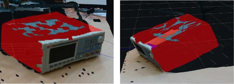
a b
Fig. 2. An example of the formation of empty areas
Рис. 2. Пример образования пустых областей
This feature is caused by the fact that the system has an idea only of the visible part of the scene, which leads to large inaccuracies in the construction of the three-dimensional shape of the object (the cloud of three-dimensional points is also noisy) or to the need for a circular viewing of the object by a stereo camera.
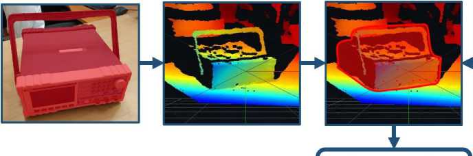
As it is seen in fig. 3, a, c, the method of direct reconstruction does not always provide sufficient coverage of the surface of the object with three-dimensional points, which is especially noticeable when only one side of the object is visible. It can also be seen that when the spatial position of an object or a stereo camera changes, the resulting density is highly dependent on the level of perpendicularity of the object plane relative to the stereo camera. So, in fig. 3, a the information about the upper surface of the object is very noisy, however, as the camera position changes, the reconstruction becomes more and more dense (Fig. 3 , b, c ).
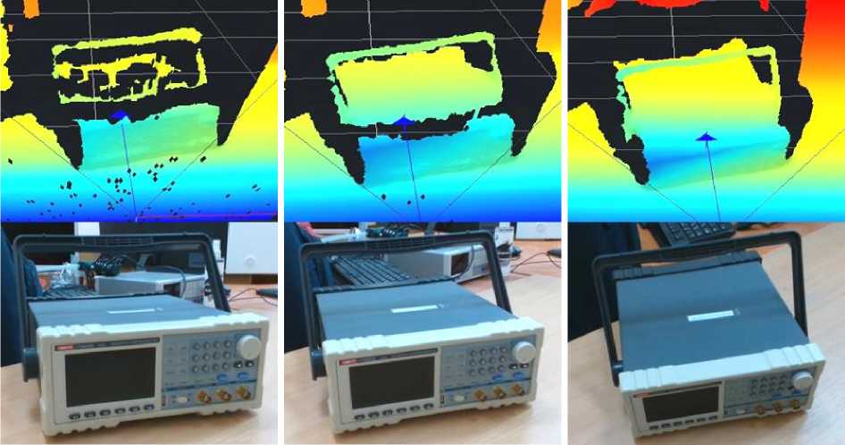
b
Fig. 3. An example of direct reconstruction of an object
Рис. 3. Пример прямой реконструкции объекта
To solve this problem, it is proposed, instead of trying to directly reconstruct the shape of an object, to use a replacing three-dimensional model, selected in accordance with the classified object. Such an approach will not only simplify the reconstruction of the scene and objects on it (since the system will be able to reconstruct visible objects during a single inspection), but also increase the flexibility of the object capture algorithm, which is ensured by the presence of a full three-dimensional model, on the basis of which it is better to calculate the trajectory compared to the noisy approximate voxel model. The approach under consideration involves solving three problems: determining the method of object reconstruction, correlating the position and dimensions of the replacing model and the target object.
2.4. 3D shape reconstruction
Detected target objects are reconstructed on the 3D map of the robotic manipulator by replacing them with a similar 3D model. The method under consideration involves the preparation of the necessary data set to form a three-dimensional model. One of the methods of formation is the use of a completely identical three-dimensional model, which makes it possible to achieve high fidelity in the reproduction of the target object. However, this approach has a significant drawback, since the model is formed in advance and is integral. Therefore, in the case of reproducing an object of complex shape, the three-dimensional model will have many details that are necessary only for calculating the direct interaction of the manipulator with the object itself, and in the case of the presence of a large number of complex objects on the scene, resource costs will increase significantly.
In this regard, it is proposed to carry out the reconstruction of the target object using geometric primitives based on the prepared reproduction template. The proposed solution has the following advantages: reducing the amount of memory required for storing models (since only a description of their structure is stored); the ability to vary the degree of detail of the object reconstruction in real time depending on the requirements for the system. For example, when calculating the general trajectories of the manipulator, an accurate (detailed) idea of the surrounding objects is not required. However, at the stage of interaction with the target object, more precise details can significantly affect the construction of the algorithm for interacting with the object. Another advantage is the ability to correlate point details of a three-dimensional object model (button, switch, connector) with their functional purpose, which allows implementing more advanced algorithms for interacting with objects.
2.5. Obstacle object
One should also take into account the probability of the appearance of objects on the scene that are absent in the training sample, as a result of which they are not recognized by the neural network. During normal operation, such objects are of no interest and are not taken into account by the system. However, in the case when such an object intersects with the trajectory of the manipulator or visually overlaps the target objects, it is classified as an obstacle object and must be taken into account when building a three-dimensional map and calculating the trajectory of the manipulator. In this regard, there appears an additional task of detecting and determining the shape of such objects.
Since the recognition of obstacle objects is not initially provided by the system, detection is possible only by indirect signs. Such signs can be detected in two cases: 1) when the obstacle object partially overlaps the target object (as a result of which the object will be recognized, but with a lower percentage of neural network identification); 2) when the obstacle object completely overlaps the target object, where it is reconstructed on a three-dimensional map.
Regardless of the indirect sign, the reconstruction of the obstacle object is based on the residual layer (layer without target objects). The presented layer is obtained after applying the operation of the symmetrical difference between the layers of the depth map and segmented objects. The region of occurrence of an indirect feature is compared with the residual layer, as a result of which the approximate contour of the obstacle object is calculated, which is additionally processed by the Min-Cut algorithm. The described principle is briefly shown in fig. 4, where the area of occurrence of an indirect feature is highlighted with a blue outline, which allows extending the segmentation mask to the obstacle object.
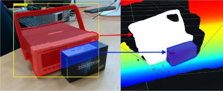
Fig. 4. Determining the shape of the obstacle object
Рис. 4. Определение формы объекта-препятствия
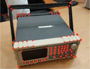
Fig. 5. Keypoints of the object
2.6. Keypoints
For further reconstruction of a three-dimensional map, it is necessary to determine the spatial characteristics (orientation and dimensions) of the target objects. It is important to take into account that neural networks classify and segment an object as a whole, “semantically” not distinguishing its surfaces, and therefore it is necessary to develop an additional method for detecting the distinguishing features of an object that uniquely determine the spatial characteristics of the target object.
The presented problem is proposed to be solved by the method of determining keypoints. Various areas of geometric change in the surface of an object (faces, corners and other visually expressed places) can act as points (fig. 5).
Deep learning models may be able to predict the location of keypoints. In this formulation, we mean solving the problem of regression analysis. In this case, the pixels of the image of the target object act as independent input parameters, and the coordinates of the object’s keypoints are the dependent input parameters, for which the neural network architecture must be modified with an additional output layer “Keypoints mask”. The resulting architecture is shown in fig. 6.
Рис. 5. Опорные точки объекта
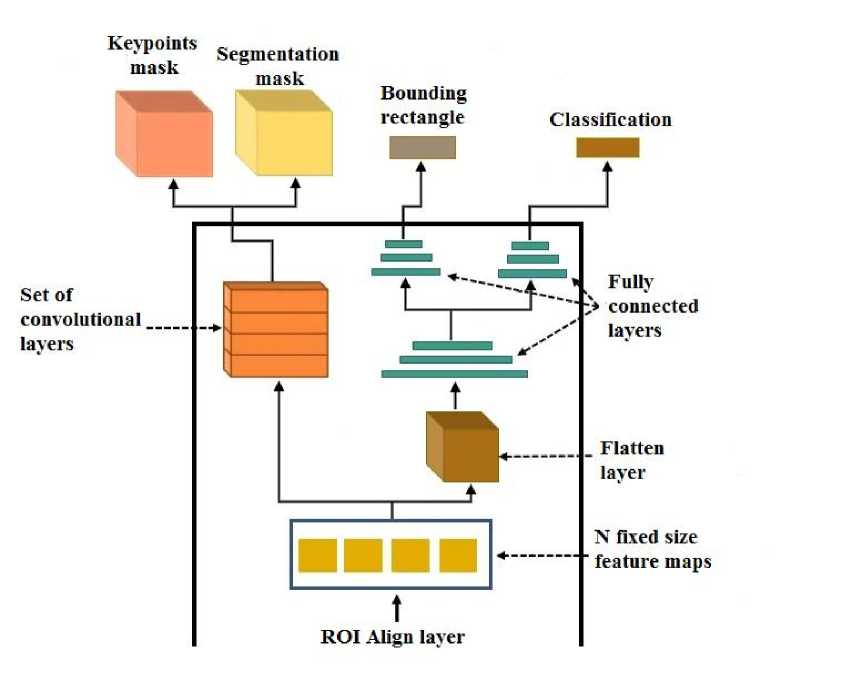
Fig. 6. Modified convolutional neural network architecture
Рис. 6. Модифицированная архитектура сверточной нейронной сети
Thus, the method for calculating the characteristics of a replacing model takes three layers as input: an object segmentation map, a map of features of keypoints, and a depth map. To obtain a map of features of keypoints, an RGB image layer is fed to the input of the neural network, the output is an array of values
[ N x k ] f , (1)
where N is the number of target objects detected by the neural network; k is a list of detected keypoints of each object, which is a map of the probability of presence on the RGB image.
Each element of the array (1) consists of three subelements: x , y , p . The variables x , y are the coordinates of the keypoint on the RGB image, the element p e (0,1] determines the probability of the existence of the keypoint.
For further transformation into a three-dimensional surface, a depth map is used, onto which data from the array (1) is projected. As a result, a layer of approximate estimation of objects is obtained, on the basis of which it is already possible to approximately estimate the spatial and dimensional characteristics of the target objects.
However, it should be taken into account that the resulting segmentation mask using YOLACT EDGE can be noisy and a discrepancy between the RGB image and the depth map is inevitable. Therefore, segmentation on the resulting layer 2 is additionally refined based on the method of geometric post-processing of the depth map, for which 3D point cloud clustering is used applying the Min-Cut algorithm [14].
The presented method is intended for segmentation of objects in a cloud of three-dimensional points, each individual point is considered as a vertex. When joining adjacent vertices with edges, the surface of the object is formed. Considering some vertices as foreground priorities, the method cuts out the foreground object from the 3D point cloud based on the results of the edge weight calculations. The Min-Cut input is the data of the detected array keypoints (1) as the foreground priority, as well as a layer of segmented objects to limit the processing area within the target object. To estimate the weight of the edges, it is necessary to determine two parameters of the equation: the cost of smoothing the edges and the background penalty P
( i ^ 2
C = e , (2)
where l is the length of the edge (the farther the vertices are from each other, the more likely it is that they will not be connected); σ is a user-defined parameter.
The background penalty is the weight of the points associated with the foreground points. In this case, for the joint point J ( Jx , Jy , Jz ), the input parameter r is set - the maximum horizontal ( X – Y plane) radius of the foreground objects, then for the neighboring point J ( x , y , z ) its background penalty equals
P =
( x — Jx ) + ( y — Jy )
r
After applying the Min-Cut method, the output is a layer of the final assessment of the characteristics of objects, on the basis of which it is already possible to accurately assess the spatial and dimensional indicators of the detected objects.
2.7. Metric to evaluate the detection of keypoints
The task of detecting the keypoints of an object is a relatively new direction in the field of neural networks, so it is necessary to identify methods for evaluating the results of their work. To evaluate the detection of keypoints, a metric called object keypoint similarity (OKS) is used. The metric quantifies the proximity of the predicted position of the keypoint relative to the true (expected) position. The
OKS value approaches 1 as the predicted keypoint approaches the true position. The formula for evaluation looks like this:
( d 2 У
OKS = exp - -2^ , (4) v 2 s ki > where di is the Euclidean distance between the predicted and true position; s is the scale of the object and ki is a constant for a particular keypoint (a measure of the standard deviation of a particular keypoint from the expected location).
The variable s refers to the scale of the object. The larger the object is, the less strictly the error in determining the position of the keypoint should be evaluated. This method is provided by the fact that if the object is large, then it is acceptable to predict the keypoint slightly away from the true keypoint. However, if the object is small, a small deviation from the truth may cause the predicted keypoint to be outside the object.
A feature of the OKS metric is that the metric evaluation will be equivalent for all predicted keypoints that are at a certain radial distance from the true position. Fig. 7 shows an illustrative example of the evaluation of the keypoint "button" detection.
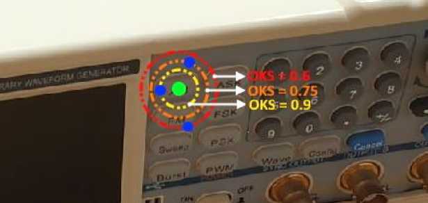
Fig. 7. An example of evaluation by the OKS metric
Рис. 7. Пример оценки метрикой OKS
In fig. 7 the green dot represents the desired position of the keypoint (the button was chosen as an example), and each of the three blue dots are possible examples of the position of the predicted keypoint. Thus, in the above example, three concentric circles correspond to the predicted keypoints.
2.8. Determination of spatial characteristics
As it was noted in Chapter 2.3, after the reconstruction of the three-dimensional shape of the object, it is also necessary to correlate the spatial position and dimensions of the replacing model and the target object.
The solution of the first problem is based on the processing of the layer of keypoints obtained from the neural network output, as well as the depth map. The spatial position of the detected keypoints of the target object is compared with similar points on the resulting 3D model, which makes it possible to determine its orientation. In its turn, the position is calculated based on the transformation of the local coordinates of the depth map (since the position is relative to the stereo camera) into global ones using the classical approach based on transition matrices [15; 16].
The scheme of the algorithm for solving the second problem is shown in fig. 8. The algorithm for determining object dimensions is as follows: the desired area for performing calculations on the depth map is determined based on the segmented contour of the target object, after which the area under consideration is compared with the location of the keypoints, which makes it possible to determine the length of the object's faces, on the basis of which the scaling factor of the replacing three-dimensional model is calculated.
Segmented 3D point cloud
Segmented contour
Depth map
Dimensions of the replacing 3D model
Keypoints
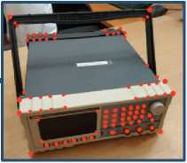
Fig. 8. The scheme of the algorithm for determining the dimensions of the replacing model
Рис. 8. Схема алгоритма определения габаритов замещающей модели
Conclusion
The presented work proposes an approach to the reconstruction of the three-dimensional shape of objects based on a computer vision system. Thanks to the use of modern methods based on convolutional neural networks and a stereo vision camera, the system is able to track the spatial position of the target objects in the manipulator swept area in real time, at the same time reconstructing a threedimensional map. In addition, on the basis of the received telemetric information, it is possible to calculate the algorithms of control and interaction of the effector with objects.
The resulting system allows expanding the range of possible applications of robotic systems in the space due to a high level of functional adaptability and robustness to changes in operating conditions. Therefore, the system can be used as a part of a mechatronic manipulator when deploying solar panels or LTC as an auxiliary and / or emergency system. The presence of a recognition system provides an analysis of the surrounding space, thereby providing feedback on the process of revealing structural elements, providing the ability to troubleshoot in case of emergency situations. For example, in case of incorrect deployment of any part of the structure, the system is able to adjust the manipulator control algorithm, which will correct the problems that have arisen and mitigate possible consequences.
References Application of the computer vision system reconstructing the three-dimensional form of space technology objects
- Belonozhko P. P. [Space Robotics: Experience and Development Prospects]. VKS. 2018, Vol. 94, No. 1, P. 84–93 (In Russ.).
- Belonozhko P. P. [Space robotics for installation and service. Potential tasks, advanced systems concepts]. VKS. 2019, Vol. 99, No. 2, P. 84–97 (In Russ.).
- Beklemishev N. D. et al. Algoritmy upravleniya dvizheniem skhvata manipulyatora [Motion control algorithms of the manipulator gripper]. Preprinty IPM im. M. V. Keldysha. 2017, No. 47, 36 p.
- Buyanov A. A., Vlasov A. I. Makeev S. S. [Research on neural network algorithms used for pattern recognition]. Molodye uchenye – nauke, tekhnologiyam i profobrazovaniyu dlya ustoychivogo razvitiya problemy i novye resheniya 2-ya Mezhdunar. konf. SN. [Young Scientists to Science, Technology, and Vocational Education for Sustainable Development: Problems and New Solutions]. 2000, P. 22–25 (In Russ.).
- Medvedev M. V., Kirpichnikov A. P. [Three-dimensional reconstruction of objects in the vision system of a mobile robot]. Vestnik Kazanskogo tekhnologicheskogo universiteta. 2014, No. 15. P. 326–330 (In Russ.).
- Li Y. et al. SplitFusion: Simultaneous tracking and mapping for non-rigid scenes. IEEE International Conference on Intelligent Robots and Systems. 2020, P. 5128–5134.
- Zhou Z. et al. Learning-based object detection and localization for a mobile robot manipulator in SME production. Robot. Comput. Integr. Manuf. 2022, No. 73. P. 102229–102241.
- Shi S. et al. PV-RCNN: Point-voxel feature set abstraction for 3D object detection. Proceedings of the IEEE Computer Society Conference on Computer Vision and Pattern Recognition, 2020, P. 10529–10538.
- Oh J. K., Lee S., Lee C. H. Stereo vision based automation for a bin-picking solution. Int. J. Control. Autom. Syst. 2012, No. 10, P. 362–373.
- Klekho D. Yu., Karelina E. B. Batyev Yu.P. [Using convolutional neural network technology in image object segmentation]. Vestnik MGUL – Lesnoy vestnik. 2021, Vol. 25, No. 1, P. 140–145 (In Russ.).
- Makarenko, A. A., Kalayda V. T. [Face Image Detection Method for Video Monitoring Systems Based on Neural Network]. Izvestiya TPU. 2006, Vol. 309, No. 8, P. 113–117 (In Russ.).
- Bolya D. et al. YOLACT: Real-time instance segmentation. Proceedings of the IEEE International Conference on Computer Vision, 2019, P. 9157–9166.
- Liu H. et al. YolactEdge: Real-time Instance Segmentation on the Edge. arXiv preprint arXiv, 2021. Available at: https://arxiv.org/abs/2012.12259.
- Golovinskiy A., Funkhouser T. Min-cut based segmentation of point clouds. IEEE 12th International Conference on Computer Vision Workshops, ICCV Workshops, 2009, P. 39–46.
- Luu T. H., Tran T. H. 3D vision for mobile robot manipulator on detecting and tracking target. ICCAS 2015 – 2015 15th International Conference on Control, Automation and Systems, Proceedings, 2015, P. 1560–1565.
- Khomchenko V. G. Robototekhnicheskie sistemy. [Robotics systems]. Omsk, OmGTU Publ., 2016, 195 p. A. S.
