Аpplication of the propulsion subsystem on the base of SPT-100V plasmic thruster to orbit raising and orbit control of the Express-80 and Express-103 spacecraft

Author: Ermoshkin Yu.M., Vnukov A.A., Volkov D.V., Kochev Yu.V., Simanov R.S., Yakimov E.N., Grikhin G.S.
Journal: Siberian Aerospace Journal @vestnik-sibsau-en
Section: Aviation and spacecraft engineering
Article in issue: 3 vol.22, 2021.
Free access
Recently, there has been an increase of interest in satellite orbit raising using electric propulsion subsys-tems. Theoretic analyses and practical experience demonstrate that while orbit raising to the geostationary orbit (GEO) via a transfer orbit is feasible, it requires a certain amount of time due to the thrust of onboard electric thrusters being low (40-300 mN) and thus incomparable with that of propulsion systems of liquid propellant thrusters (22-400 N). Due to low thrust, orbit raising by electric thrusters is time-consuming. However, the associated increase in mass to GEO may counterbalance the long duration of satellite commis-sioning. Calculations demonstrate a potential added satellite mass on GEO of up to several hundred kilo-grams with orbit raising duration of about 6 months. In particular, with satellite mass not exceeding 2500 kg, coupled launch is possible using existing launch vehicles. ISS took into consideration the positive results ob-tained with Express-AM5, and Express-AM6 satellites to design the Express-80 and Express-103 with orbit raising in mind. Such approach allowed for a coupled launch on the Proton-M carrier rocked with a Breeze-M upper stage, and a twofold launch cost saving. To increase thrust during orbit raising and decrease its du-ration, coupled thruster operation in high thrust mode was implemented. The resulting total mass on GEO increase constituted over 700 kilograms with maneuver duration of up to 158 days. This allows performing coupled launches of heavier satellites with orbit raising by means of electric propulsion in a feasible timeframe.
Plasmic thruster, spacecraft, orbit raising, power processing unit, orbit control
Short address: https://sciup.org/148329581
IDR: 148329581 | DOI: 10.31772/2712-8970-2021-22-3-480-493
Text of the scientific article Аpplication of the propulsion subsystem on the base of SPT-100V plasmic thruster to orbit raising and orbit control of the Express-80 and Express-103 spacecraft
In the last few years, the urgency of the task of orbit raising to the target orbit with onboard electric propulsion system (subsystem) has noticeably increased [1; 2]. In some cases, this operation was performed unnecessarily, for example, in the event of a failure of the apogee propulsion system (PS) or some other anomalous situations. So, in 2011, the AEHF satellite (USA), after the failure of the apogee propulsion system, was put into geostationary orbit (GSO) by the Hall orbit correction engine BPT-4000 (XR-5) developed by Aerojet Rocketdyne [3].
In domestic practice, the operation of placing a satellite at a given position in a geostationary orbit after launching by an upper stage (the stage of bringing to a point) was carried out at each launch of spacecraft (SC) with an electric propulsion system (EPS) on board, starting with the spacecraft Kos-mos-1366 (1982). This operation can be interpreted as a small-scale orbit raising, taking into account the relatively small value of the generated total impulse. A similar operation was carried out for satellites such as Yamal-100 (1999), Yamal-200 (2003). The orbit raising was carried out by the correction engines M-70 developed by Fakel Design Bureau [4].
Theoretical analysis and the available practice have shown that the operation of orbit raising to the geostationary orbit from some intermediate orbit is quite feasible, however, it is stretched in time, since the thrust of onboard electric propulsion engines is small (40-300 mN) and is incomparable with the thrust of liquid engines of apogee propulsion systems (22-400 N). However, the possible effect achieved in terms of an increase in the mass delivered to the GSO may outweigh the negative effect from an increase in the time for putting the satellite into operation. In particular, in MAI calculations were carried out, which showed that the additional mass of the spacecraft in the GSO can be up to several hundred kilograms with an additional launch time of about 6 months [5; 6].
There are no formal criteria for determining the optimal orbit raising time. However, it is obvious that the spacecraft operator is interested in minimizing the duration of this operation. Therefore, this parameter is determined by a reasonable balance between the value of additional mass output and the time to complete the maneuver. European experts have calculated the economic effect of the introduction of the additional detonation operation by means of the onboard electro-jet propulsion system. In particular, with a spacecraft mass of no more than 2500 kg, pair launch becomes possible. When using the Falcon 9 launch vehicle, the cost of launching one spacecraft is reduced to 25 million USD, while the overall cost reduction for the operator is 30% [7]. This approach was implemented, in particular, during the launch of the EUTELSAT 115 West B spacecraft (2015), which is considered abroad to be the first “fully electric spacecraft” [1]. Note that the concept of “all-electric spacecraft” was disclosed and refined in more detail in [8].
Calculations show that the available thrust of the engines directly affects the time of additional launch: the higher the thrust, the shorter the duration of the maneuver [6]. Therefore, it is advisable to choose the maximum possible thrust of the engines at the stage of orbit raising, based on the available power of the on-board power supply system. Variants of using powerful engines for solving the task of orbit raising are actively being considered abroad [9]. The thrust can be increased by increasing the power of a single unit, that is, using a more powerful engine, or using several (for example, two) engines of lower power at the same time. A favorable factor for increasing the power consumption of the propulsion system at the orbit raising stage is that at this stage the payload (repeater) does not work as intended, therefore there is some excess power on board. Taking into account all the limiting circumstances, the duration of the raisng orbit stage for 6 months can be taken as the upper limit acceptable to the consumer, although, of course, this limit is conditional. Based on the accepted time limit for the operation, it is possible to determine the maximum value of the output mass at a known thrust of the engines.
In Russia, the orbit raising stage was planned and implemented during the launch of the Express-AM5 (2013) and Express-AM6 (2014) heavy spacecraft, the mass of which exceeded the capabilities of the launch vehicle. These spacecraft were created in JSC ISS [10; 11]. The orbit raising was carried out by an onboard electric propulsion system based on the well-known SPT-100V engines developed by Fakel Design Bureau. One engine was running during the maneuver. The Express-AM5 spacecraft produced about 20 kg of xenon used as a working body , the total impulse was 298 kN·s, the total duration of the operation was 67 days. The initial mass of the spacecraft in the GSO was 3360 kg, the effect in terms of increasing the mass was about 110 kg. On the Express-AM6 spacecraft, due to increased errors of orbit raising, the task turned out to be more voluminous. 43.6 kg of xenon were produced, the total impulse was 650 kN·s, the total duration of the operation was 118 days.
Taking into account the positive experience gained on the Express-AM5 and Express-AM6 spacecraft, the design of the next Express-80, Express-103 spacecraft was also carried out with the expectation of performing the orbit raising, which made it possible to use a pair launch by a single Proton-M carrier rocket with a Briz-M upper stage. This made it possible to halve the launch costs, which, as noted above, is extremely beneficial for the customer and the spacecraft operator. The mass of the Express-80 spacecraft on the GSO according to the project was 1960 kg, Express-103 – 2065 kg, the total effect from the use of orbit raising stage – 775 kg. The launch mass in the geotransfer orbit after separation from the upper stage was 2110 and 2280 kg respectively. To increase the thrust at the stage of orbit raising and reduce its duration, the engines were operated in pairs. This work is devoted to the application of a propulsion system based on engines of the SPT-100B type for the operation of orbit raising of the Express-80 and Express-103 spacecraft into geostationary orbit.
The composition of the propulsion subsystem of orbit control and orbit raising. The choice of the type of engines, their layout on the satellite
The propulsion subsystem for orbit raising and orbit control tasks includes six correction units based on the SPT-100B engine created at the Fakel Design Bureau, Russia (Fig. 1, 2), three PPU-Mk2 devices, six filtration units (FU) (TAS-B, Belgium, Fig. 3, 4), a xenon supply unit (ISS JSC, Russia, Fig. 5), a high-pressure xenon tank (ISS JSC, Russia, Fig. 6).
Based on the convenience of the layout on the satellite, a block consisting of an thruster and a gas distribution unit (BGR) in a vertical layout was used for orbit-raising, in which the thruster was installed on the BGR (Fig. 1). To correct the orbit, blocks were used in the horizontal layout, when the BGR is placed on the platform next to the thruster (Fig. 2). This arrangement is more convenient for placing the blocks under the satellite solar battery packs in the transport position.
The plasma thruster SPT-100B, widely known both in Russia and abroad, was chosen. The reason for this choice was the extensive flight history of this thruster, its high reliability, service life and sufficient thrust level with acceptable efficiency.
These blocks (with the exception of PPU and FU blocks) were combined into a system by interblock pipelines according to the scheme shown in Fig. 7. All thrusters were powered by a working body (Xe) from a common tank. To reduce the pressure of the working body the required one at the thruster inlet, a single two-channel xenon supply unit was used.
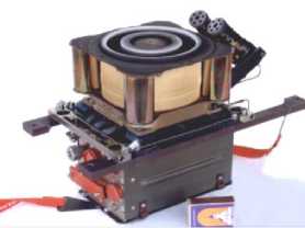
Fig. 1. Orbit raising thruster unit on the base of SPT-100B
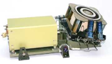
Fig. 2. Orbit control thruster unit on the base of SPT-100B
Рис. 1. Блок коррекции довыведения на базе СПД-100В
Рис. 2. Блок коррекции орбиты на базе СПД-100В
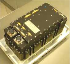
Fig. 3. PPU-Mk2 unit
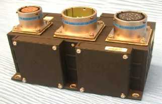
Fig. 4. Filter unit
Рис. 3. Прибор PPU-Mk2
Рис. 4. Блок фильтрации FU
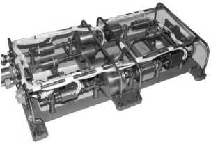
Fig. 5. Xenon feed unit
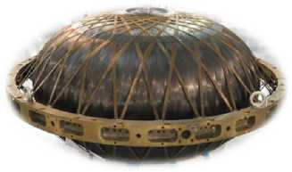
Fig. 6. High pressure xenon tank
Рис. 5. Блок подачи ксенона
Рис. 6. Ксеноновый бак высокого давления
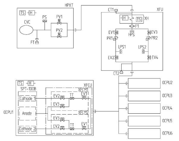
Fig. 7. Propulsion subsystem functional scheme:
XHPT – xenon high pressure tank; XFU – xenon feed unit; GDU – gas distribution unit; FN – filling neck;
TN – test neck; HPS – high pressure sensor; LPS – low pressure sensor; PS – pressure sensor;
CCB – composite balloon ; HT – heater; PV – pyrovalve; WFH – working body heater; PR – pressure reducer; TC – therma lthrottle; F – filter; EV – electric valve (control valve); t – temperature sensor
Рис. 7. Функциональная схема двигательной подсистемы:
КБВД – ксеноновый бак высокого давления; БПК – блок подачи ксенона; БГР – блок газораспределения;
ГЗ – горловина заправочная; ГП – горловина проверочная; ДВД – датчик высокого давления; ДНД – датчик низкого давления; ДД – датчик давления; КБК – корпус баллона композитного; НГ – нагреватель;
ПК – пироклапан; ПРТ – подогреватель рабочего тела; РД – редуктор давления; ТД – термодроссель;
Ф – фильтр; ЭК – электроклапан (клапан управляющий); t – датчик температуры
One of the important issues that each manufacturer of spacecraft solves in accordance with the preferences and the established technical school, is the placement of thrusters on the spacecraft frame and the concept of their use. Various technical solutions are possible here, each of which has its own advantages and disadvantages. In JSC ISS for the spacecraft Express-80 and Express-103 the concept of separate use of thrusters for orbit-raising and subsequent correction of the orbit was adopted. The thrusters were fixed to the spacecraft frame motionlessly. This approach has its advantages, although there are also known options for placing thrusters on gimbsls or manipulators [12]. Thrusters 1–4 are used to correct the longitude and inclination of the orbit, and thrusters 5 and 6 are used for orbitraising operation (Fig. 8). The advantage of this concept is that the orbit-raising thrusters have practically no thrust losses due to the small deviation of their axes from the required direction. Another advantage of this arrangement is that, taking into account the significant scale of the orbit-raising operation in terms of the value of the generated total impulse, the resource of the orbit correction thrusters is not consumed. The motionless attachment of the thrusters makes it possible to dispense with a rather complex thrust vector control system using gimbals or manipulators and thereby reduce the weight of the satellite platform structure. Paired placement of the orbit-raising thrusters allows one to increase the thrust when they work together.
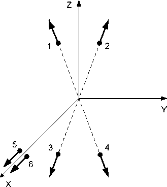
Fig. 8. Thruster units allocation along the axis of the concerned coordinate system (X – along the radius vector, Y – along to velocity vector, Z – to the North): 1–4 – orbit control thrusters; 5–6 orbit raising thrusters
Рис. 8. Расположение блоков коррекции по осям связанной системы координат (Х – по радиус-вектору, Y – по вектору скорости, Z – на Север): 1–4 – двигатели коррекции орбиты; 5–6 – двигатели довыведения
Thruster operating modes. Organization of their supply with a working body and electricity. Thruster control circuit
In addition to increasing the thrust due to the paired operation of the thrusters on the Express-80, Express-103 spacecraft, an additional method was applied – by increasing the power consumption. Due to the fact that the PPU-Mk2 device allowed adjusting the output parameters in a certain range, the power of the SPT-100B engine was selected, different from the nominal value of 1350 W. In the modified mode, the discharge power was 1530 W, the expected thrust was 91.2 mN, the specific impulse was 1580 s. Trust in this mode increased by about 10%, efficiency - by 4%. It should be noted that such an increase in power and thrust turned out to be possible and practically did not affect the engine life due to the fact that this model was originally designed for a thrust of about 100 mN, which was subsequently abandoned. Therefore, an increase in power and thrust within relatively small limits from the nominal mode turned out to be possible and quite easy to implement.
For the paired operation of the thrusters, it was necessary to provide a double flow rate of the working fluid through the xenon supply unit (at a level of about 12 mg/s). Due to the fact that the previously used XFT (Fig. 5) had more than double the flow margin while maintaining the output pressure at the required level of 2.6 kgs/cm2, it was decided to apply the same type of XFT that was used earlier on previous spacecraft developed by JSC ISS.
As it was mentioned above, PPU Mk2 devices were developed and manufactured by TAS-B (Belgium) to power and control the SPT-100B thrusters [13] on the Express-80 and Express-103 spacecrafts. These devices have certain advantages over domestic power processing units (SPU). In particular, the PPU functionality allows flexible adjustment of the output parameters of the power supply and control circuits, which makes it possible to use PPU-Mk2 with various types of thrusters. Fig. 9 shows the range of possible output characteristics of the PPU-Mk2.
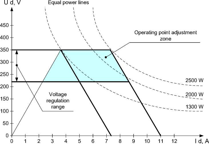
Fig. 9. Interval of the PPU-Mk2 discharge circuit possible output performances
Рис. 9. Диапазон возможных выходных характеристик разрядной цепи PPU-Mk2
The initial PPU power setting value was 1350 W, however, as mentioned above, for the Express-80, Express-103 spacecrafts, the power of 1530 W was adopted, therefore, before each correction session, the value in the form of a setpoint of 5 A current and 306 V discharge voltage was put into the PPU by on-board software.
To solve the problems of orbit raising and control, a power supply scheme for the correction units was chosen, which implies the use of three PPU-Mk2 devioces and six filtering units FU (Fig. 10).
The circuit in Fig. 10 was chosen based on capabilities of the PPU-Mk2 to control one of the two correction units using a built-in internal thruster switch unit (TSU). At the design stage, the option of using two PPU-Mk2, one external thruster switch unit (ETSU) and six filtering units FU was also considered. Such a solution would reduce the mass of the power electronics of the propulsion subsystem by about 20%. However, this option required the modification of the external ETSU for the onboard 100 V power bus, additional costs of financial resources and time, so it was abandoned.
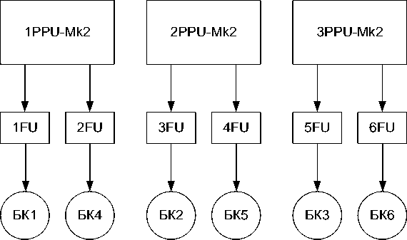
Fig. 10. Implemented power supply scheme of the correction units
Рис. 10. Реализованная схема запитки блоков коррекции
Control of the propulsion subsystem from the onboard software
The traditional technical solution used in JSC ISS to control the process of starting and control the operation of thrusters is the use of onboard software (OBSW), implemented in the central onboard computer. This makes it possible to simplify the construction and logic of transformation and control systems (PPU). However, PPU Mk2 instruments used as part of the correction system, the Express-80, Express-103 spacecraft had built-in logic that allows them to independently implement the engine startup sequence. Taking into account this circumstance, the tasks of a limited scope were assigned to the OBSW of the correction system, namely:
-
– entering into PPU the setting of 5A for current, 306 V for discharge voltage, 12 A for cathode heating current;
-
– reading the values of telemetric parameters;
-
– issuing commands for the formation of PPU modes;
-
– shutdown of PPU and thrusters in abnormal situations;
-
– formation of statistical and diagnostic reports.
This version of the PPU of the correction system has passed a full cycle of autonomous and complex testing, as well as verification at the stage of electrical tests of the spacecraft.
Integration of the propulsion subsystem
Taking into account the fact that the composition of the propulsion subsystem of the Express-80, Express-103 spacecraft differed significantly from that previously adopted on other spacecraft developed by ISS JSC, primarily by the presence of three PPU-Mk2 devices, a new thruster operating mode, their paired operation, considerable attention was paid to the integration of the propulsion subsystem. In this case, integration means checking the joint operability of the components of the propulsion subsystem (with the exception of the xenon tank) when the thrusters are actually turned on. In order to exclude irreversible operations, such as the detonation of pyrovalves, a technological balloon was used in the test process instead of a standard tank to accommodate the xenon stock. The tests were carried out in a vacuum chamber with a volume of 80 m3 (Fig. 11).
During the tests, all telemetry parameters of the propulsion subsystem were recorded. In addition, the thrust of the thrusters, the pressure in the vacuum chamber, and the temperature of the seats on which the PPU Mk2 devices were installed were recorded. Typical thrust graphs at start-up and operation of orbit-raising thrusters are shown in Fig. 12. The paired operation of the thrusters in the vacuum chamber is shown in Fig. 13. During the integration tests, the joint operability of the propulsion subsystem units was demonstrated, the compliance of all the main parameters (power, thrust, specific consumption) with the required values, transient characteristics were removed when turning on and off the thrusters, as well as pulsation parameters during stationary operation.
At the stage of electrical testing of the spacecraft, the operability of the orbit correction system was also demonstrated, including the participation of specialized on-board software, while electric simulators were used instead of thrusters, since it is impossible to firing of plasma thrusters in atmospheric conditions.
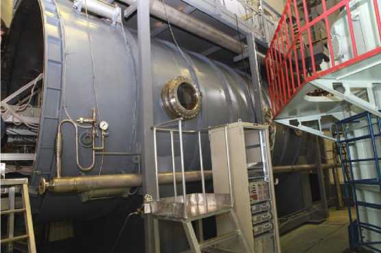
Fig. 11. The extexrior of the GVU-60 test bench vacuum chamber
Рис. 11. Внешний вид вакуумной камеры стенда ГВУ-60
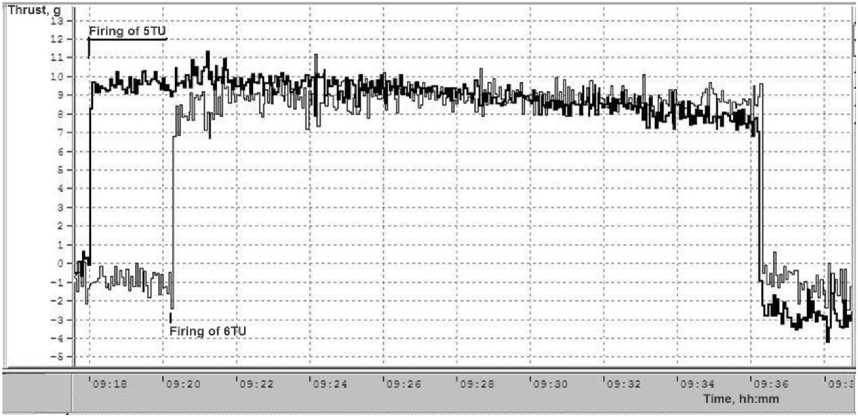
Fig. 12. Thrust of the orbit raising thrusters with firing by the PPU Mk2 in the vacuum chamber
Рис.12. Тяга двигателей довыведения при включении от PPU mk2 в вакуумной камере
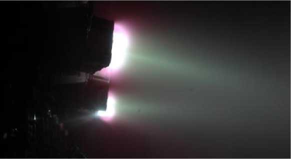
Fig. 13. Paired work of SPT-100B thrusters during the integration test
Рис. 13. Парная работа двигателей СПД-100В во время интеграционных испытаний
Performing an orbit-raising maneuver
Each spacecraft was filled with xenon up to the full tank capacity of 300 kg. The launch into a ge-otransitional elliptical orbit was carried out on July 31, 2020. Geotransitional transfer orbit parameters: apogee – 54900 km, perigee – 16670 km, eccentricity - 0.453, inclination ~ 0.7° [14].
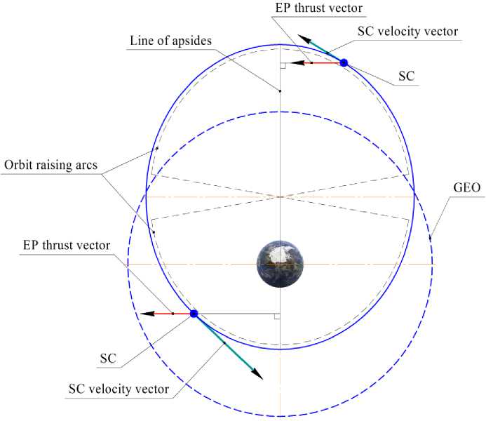
Fig. 14. SC Express-80 and Express-103 orbit raising scheme
Рис. 14. Схема довыведения КА «Экспресс-80» и КА «Экспресс-103»
The orbit raising was carried out according to the modified Spitzer scheme (Fig. 14), in accordance with the method [15] orbit raising consisted in the correction of the eccentricity of the orbit with the simultaneous correction of its period in order to organize the spacecraft drift to the operating point on the GSO and passively, due to natural evolution, by decreasing the inclination. Such a scheme made it possible, firstly, to exclude a separate stage of bringing the spacecraft to the working longitude, thus reducing the total time of spacecraft commissioning into normal operation, and, secondly, to reduce the cost of correcting the eccentricity, providing a lower eccentricity of the initial orbit of raising due to incomplete correction of the inclination by the upper stage. For the purpose of organizing the continuous orientation of the thrust vector perpendicular to the line of the apses of the injection orbit, the spacecraft was turned relative to the OZ axis of the linked coordinate system until the OX axis of the linked coordinate system coincided with the perpendicular to the line of the apses.
Orbit raising of the Express-80 spacecraft, combined with bringing it to the operating point at 80.0° E, was carried out in 149 days with a planned duration of 152 days. During this time, 232 paired corrections were performed with a total duration of engine operation of 5767 hours. The xenon con-sumtion for additional injection and bringing to the operating point was 124 kg. The results of trajectory measurements during and after the completion of orbit raising confirmed the correspondence of the real thrust of the correction thrusters to the project values.
Orbit raisisng of the Express-103 spacecraft was carried out according to a method similar to that of the Express-80. This operation, combined with bringing the spacecraft to a point on GSO 103.0° E, was carried out in 158 days with a plan of 160 days. During this time, 257 paired corrections were carried out with a total duration of 6046 hours of operation of the engines. The xenon consumption was 130 kg.
Conclusion
The presented materials allow us to conclude the following:
-
1. The orbit-raising maneuver for the Express-80 and Express-103 satellites was completed successfully. The technique of this operation has been tested. Its duration for the Express-80 spacecraft was 149 days, for the Express-103 spacecraft - 158 days, which meets the target dates. This consumed 124 and 130 kg of xenon, respectively. Such a large-scale orbit raising maneuver was carried out in the Russian Federation for the first time. The beneficial effect from the application of this concept was for two spacecraft a total of 775 kg, which made it possible to fit the payload of increased productivity on board the spacecraft.
-
2. The joint performance of two engines, as well as control and conversion devices with a duration of about 3000 h, as well as the ability of the xenon supply unit to provide double flow rate of the working body with the required inlet pressure in the thrusters, has been demonstrated. Thanks to the capabilities of PPU Mk2 devices, a mode of increased thruster power has been implemented, which allows to increase thrust by about 10% and economy – by 4 %. According to the radio monitoring of the orbit, the expected thrust of the engines has been confirmed.
-
3. The experience gained allows to carry out paired launches of a spacecraft of increased mass with orbit raising to the GSO with its own thrusters an acceptable time frame if necessary. Increased thrust units can be used in the future to reduce the duration of orbit raising.
References Аpplication of the propulsion subsystem on the base of SPT-100V plasmic thruster to orbit raising and orbit control of the Express-80 and Express-103 spacecraft
- Casaregola C. Electric Propulsion for Station Keeping and Electric Orbit Raising on Eutelsat Platform. Joint Conference of 30th ISTS, 34th IEPC, 6th NSAT, Kobe-Hyogo, Japan, July 4–10, 2015, IEPC-2015-97, 6 p.
- Yakovlev A. V., Vnukov A. A., Balandina et al. [Injection of a spacecraft into a geostationary orbit by a combined method]. Vestnik SibGU. 2016, Vol. 17, No. 3, P. 782–789 (In Russ.).
- Hoskins W. A., Cassady R. J., Myers R. et al. 30 Years of Electric Propulsion Flight Experience at Aerojet Rocketdyne. 33st International Electric Conference, The George Washington University, USA, October 6–10, 2013, IEPC-2013-439, 12 p.
- Testoedov N. A., Makridenko L. A., Sevast’yanov N. N. et al. Overview of Electric Propulsion activity in Russia. 30th International Electric Conference, Florence, Italy, Sept. 17–20, 2007, IEPC-2007-275, 16 p.
- Konstantinov M. The analysis of electric propulsion characteristics on efficiency of transport maneuvers. 30th International Electric Propulsion Conference, Florence, Italy, Sept. 17–20, 2007, IEPC-2007-212, 18 p.
- Obukhov V. A., Petukhov V. G., Popov G. A. Application of Stationary Plasma Thrusters for Spacecraft Insertion into the Geostationary Orbit. Proceedings of the International Astronautical Con-gress, IAC. Series “63rd International Astronautical Congress 2012, IAC 2012” 2012. P. 7569–7577.
- J. Gonzalez del Amo. European Space Agency Activities in Electric Propulsion. 33st Interna-tional Electric Conference, The George Washington University, USA, October 6–10, 2013, IEPC-2013-37, 9 p.
- Ermoshkin Yu. M., Volkov D. V., Yakimov E. N. On the concept of “all-electric spacecraft”. Siberian Journal of Science and Technology. 2018. Vol. 19, No. 3, P. 489–496 (In Russ.).
- Trescott J. A., Horton J. F., Rapoport S.The Benefits of Continued Advances in the Propulsive Capability of the Electric GEO Communications Satellite. The 36th International Electric Propulsioin Conference, University of Vienna, Austria, Sept. 15–20, 2019, IEPC-2019-212, 10 p.
- Krasil’nikov A. [Powerful telecommunication Express-AM5]. Novosti kosmonavtiki. 2014, No. 2, P. 38–41 (In Russ.).
- Krasil’nikov A. [The hard way of Express-AM6]. Novosti kosmonavtiki. 2014, No. 12, P. 42–45 (In Russ.).
- Rueda P., Schneider A. Electra – a Flexible Full Electric Propulsion Platform for GEO Mis-sions. Aerospace Europe Bulletin, July 2019, P. 21–23.
- Bourguignon E., Fraselle S. Power Processing Unit Activities at Thales Alenia Space in Bel-gium. The 36th International Electric Propulsioin Conference, University of Vienna, Austria, Sept. 15–20, 2019, IEPC-2019-584, 8 p.
- Zapusk kosmicheskikh apparatov «Express-103» i «Express-80» [Launch of the spacecraft “Express-103” and “Express-80”]. Available at: https://www.roscosmos.ru/28882/ (accessed 18.03.2021).
- Doronkin M. N., Babanov A. A., Vnukov A. A. et al. Sposob vuvedeniya kosmicheskogo appa-rata na geostatsionarnuyu orbitu s ispol’zovaniem dvigatelei maloi tyagi [Method of launching a spacecraft into geostationary orbit using low-thrust engines]. Patent RF, No. 2014127670/11, 2016.
