Approach to optimization of the magnetic circuit of a three-phase induction plant

Author: A. A. Tyapin, E. S. Kinev, S. S. Bezhitsky
Journal: Siberian Aerospace Journal @vestnik-sibsau-en
Section: Technological processes and material science
Article in issue: 3 vol.20, 2019.
Free access
The article describes an approach to optimization of the electromagnetic regimes of an induction metallurgical plant, designed to mix liquid aluminum under the influence of a running magnetic field. To improve the properties of the molten metal in the furnace, short pole linear magnetohydrodynamic machines with copper windings and a steel core are used. The open configuration of the magnetic circuit and the magnetic coupling between the windings of the inductor lead to asymmetry of the magnetic field. As a rule, a low-frequency transistor inverter is used in the power supply system of metallurgical machines intended to affect non-ferrous metals. Asymmetrical currents in the phases create specific modes of the frequency converter, close to emergency, and a two-phase, three-phase or multi-phase power supply system may become unbalanced. To calculate the integral magnetic fluxes in the toothed zone of an induction installation, it is convenient to apply a multiphase nonlinear model of a magnetic circuit. As a result of the iterative calculation, vector magnetic flux diagrams are obtained and the tractive forces in the melt are estimated. The best conditions for the impact on the melt are obtained with a given objective function when searching for options during optimization of the magnetizing forces of the windings.
Three-phase induction plant, induction MHD machine, mathematical modeling, non-linear model of the magnetic circuit, magnetic flux vector diagram, three-phase IGBT inverter, parametric optimization
Short address: https://sciup.org/148321700
IDR: 148321700 | UDC: 621.31; 66.04 | DOI: 10.31772/2587-6066-2019-20-3-398-408
Text of the scientific article Approach to optimization of the magnetic circuit of a three-phase induction plant
Introduction . The electromagnetic inductor is a working body of the complex MHD-mixing liquid aluminum [1]. The necessary technological characteristics of the inductor are provided when it is powered by an IGBT inverter, and the frequency converter modes differ significantly from the typical ones which are used for an adjustable asynchronous electric drive [2]. Current inverters operating at the edge of the range at a frequency of about 1 Hz are used to power the induction machines of aluminum stirrers. The heat dissipation mode of power modules at switching frequencies up to 1 kHz is estimated as moderate. However, the climatic conditions of the metallurgical shop can be very difficult, which often leads to the need to equip the inverter with air conditioning systems with additional air purification [3].
To implement the current inverter mode, in the phase of the converter, the stable operation of the modules must be ensured, with the utilization or conversion of power in the antiphase state of voltage and current [4].
The transformation of the phase of a three-phase inverter into a current source significantly distinguishes its mode, typical for the state of the voltage source [5].
The output of the frequency converter to the mode is performed by stepwise acceleration according to a slowed-down volt-second characteristic, which limits the operation of hardware and algorithmic protections.
Inductors of MHD machines have a low natural power factor of MHD devices, rarely exceeding 0.05–0.1 in the area of lagging currents [6]. The steady-state linear currents of a transistor converter for most induction machines (MI) of a longitudinal field, average size (up to 5 tons), take values in the range of 200–350 amperes, and linear voltages are not higher than 380 V. A draft of the induction installation under the furnace in the melt bath area is shown in fig. 1.
The concomitant operational factors of the inverters, related to the effects of asymmetry during the intensive energy consumption of the MHD-mixing complexes of aluminum, is a high level of non-sinusoidal currents of the distribution network. The practical operation of MHD complexes showed that with a steady-state inductor power of about 45 kW and a natural value of cosφ = 0.1, the consumption of the frequency converter from the workshop distribution point can reach 120–150 kVA or more, with significant internal generation of the power source [3; 5].
The appearance of higher harmonics in the network is due to the operation of a controlled rectifier of the input module of the frequency converter, designed for accelerated power gain by a capacitor bank of a DC link. It is established that the pulsating currents of a three-phase two-half-wave rectifier can lead to the appearance of a current harmonic coefficient in the network of up to 80 %. Moreover, in accordance with the specified technological mode of the MHD inductor, the curves of a
0.38 kV non-sinusoidal current consumed from a three-wire network turn out to be modulated by a sinusoidal signal with a frequency of 1 Hz. One of the means of counteracting the deterioration in the quality of electricity is changing the parameters of the DC link by significantly increasing the capacitance in the DC link [5]. There are other ways to improve the ecology of the network described in the literature [7]. It should be noted that the solution to the problem of reducing the generation of higher harmonics of the current should be solved in conjunction with the development of more advanced hardware and software equipment [8] for frequency converters, especially for metallurgical inductors.
An example of the output circuit of a three-phase transistor frequency inverter of a typical structure based on three half-bridges (D1, D2, D3) and a triangle-loaded winding of an induction MHD machine is shown in fig. 2, a . The inductor 1 with a three-zone short-circuit winding AxZcBy is connected to the inverter 2. The vector diagram of the magnetomotive force in the windings of the induction machine is shown in fig. 2, b .
An important distinguishing feature of the electromagnetic mode of a frequency inverter loaded with a three-zone induction machine is that the three-phase current system is not balanced. This means the inequality of the instantaneous power of the power supply system to zero in any section of the multiphase power circuit. The reason for this is the phase inversion and the combined inclusion of groups of induction windings. This provides a complex asymmetric structure of the magnetomotive force, for a given nature of the distribution of magnetic poles. As a preliminary analysis of the electromagnetic mode of the inductor showed, in all cases of using three-phase transistor inverters, for any topology of the windings of the induction MHD machine, the phase distribution of the currents turns out to be asymmetric [4; 5; 8]. The nature of the asymmetry may differ in the different composition of the currents of the forward and reverse sequences. Exceeding the modules of the components of the reverse and zero sequence with respect to the currents of the direct sequence may turn out to be twofold and depends on the selected winding connection scheme [5; 8]. No less important is the question of a reliable assessment of the limiting current regimes of the inverter power modules.
Formulation of the problem. In the case of phase asymmetry, a twofold difference in the operating current of adjacent quasicomplete half-bridges, during their continuous operation in the antiphase current-voltage ratio, may turn out to be a reality [9; 10]. It should be noted that the use of a universal software environment for all tasks is not the only right solution and has its limitations. For example, for converting input and output information streams, it is convenient to have data in an ASCII code that is advantageous from the point of view of the formation of hybrid models, as well as in full access to the analysis results.
This condition is extremely important when choosing the structure of an optimization project, in which it may be necessary to organize the interaction of heterogeneous software and the continuous exchange of data between program modules. Cyclic access to open result files when solving an optimization problem often forces you to form a new project shell in which automatic addressing, marking files, and data loading into different critical modules and subsystems, including those built using programming, are performed [11]. To assess the nature of the distribution of the magnetic field in the inductor, it is necessary to calculate the magnetic fluxes of the teeth and the yoke, determine their relationship and evaluate the means of their regulation. The distribution of magnetic fluxes in the melt determines the total traction force of the induction machine, so the problem can be solved using a numerical iterative model and optimization.
Solution . The solution of the problem of modeling the field in the graphical shell of modern professional software products, for the assumptions made, usually does not cause difficulties [12]. Its details can be omitted using the calculation results in the form of integral characteristics of the best options for a longitudinal magnetic field MHD machine. The calculated parameters of several induction machines obtained by modeling in a
Maxwell medium at a frequency of 1 Hz for a three-zone machine 2200 mm long with a steel core are presented in table. Options 1–2 – three-phase execution, options 3–4 two-phase.
Given in the table the results can be used for practical design of the inductor. At the same time, details of studying its energy and the interaction of integrated magnetic fluxes in the windings, yokes, teeth, and currents that cause them can be of considerable interest in clarifying the electromagnetic regime of an induction MHD machine. An electromagnetic inductor is only a part of the whole device – a complex of MHD-mixing liquid aluminum. The necessary technological characteristics of the inductor are provided when it is powered by an IGBT inverter, and the frequency converter modes are significantly different from the typical ones for an adjustable asynchronous electric drive [9; 13]. Numerous attempts to adapt common industrial converters, with standard transistor control algorithms to different types of flat MHD inductors, have not showed stably positive, stable results [3; 5]. In addition to the problems of controllability and reliability of the power link, often there are difficulties in interfacing the logic of the internal control system with the operation algorithm of the upperlevel control system controller. Therefore, it was very important to analyze the features of the inductor, fed by a low-frequency source of modified sinusoidal voltage [8; 9].
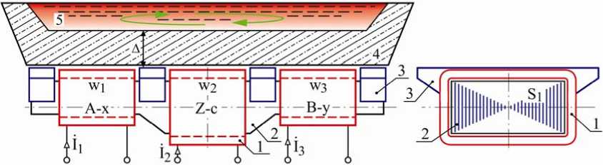
Fig. 1. Draft of the design of a three-zone induction machine
Рис. 1. Эскиз конструкции трёхзонной индукционной машины
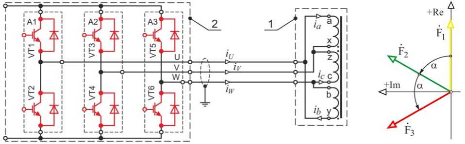
Fig. 2. Three-zone induction machine with an inverter and a vector diagram of the magnetomotive forces
Рис. 2. Трёхзонная индукционная машина с инвертором и векторная диаграмма магнитодвижущих сил
Design and operational parameters of induction machines
|
Design parameter |
Option |
|||
|
1 |
2 |
3 |
4 |
|
|
Base number of pole pairs |
2p = 1 |
2p = 4/3 |
2p = 3/2 |
2p = 2 |
|
Winding connection diagram |
AZB |
AZBX |
ABX |
ABXY |
|
Number of inductor windings, pcs. |
3 |
3 |
4 |
4 |
|
Number of inverter half bridges, pcs. |
3 |
3 |
4 |
4 |
|
Linear current load, kA / m |
87 |
82 |
94 |
89 |
|
Inverter line current, A |
220 |
220 |
350 |
350 |
|
The magnitude of the pole pitch τ , mm |
2200 |
1650 |
1467 |
1100 |
|
Rate of a magnetic field rise V 1 , m / s |
4.4 |
3.3 |
2.9 |
2.2 |
|
The mass of the winding copper inductor, kg |
969 |
1005 |
1133 |
1120 |
|
Inductor mass total mi, kg |
5019 |
4828 |
4416 |
5143 |
|
Power inductor Pi, kW |
73.0 |
77.8 |
80.8 |
82.7 |
|
Tangential force F τ , N |
476 |
647 |
646 |
375 |
|
Integral force in the melt, N |
1832 |
2111 |
1836 |
1245 |
|
The ratio of force to power, N / kW |
6.52 |
8.32 |
8.00 |
4.53 |
|
The ratio of force to mass of the inductor, N / t |
94.8 |
134.0 |
146.3 |
72.9 |
|
The speed of the melt, m / s |
2.24 |
2.48 |
2.32 |
0.97 |
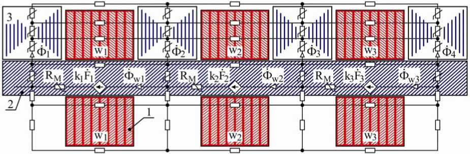
Fig. 3. Fragment of the model of a magnetic circuit of a three-zone inductor
Рис. 3. Фрагмент модели магнитной цепи трёхзонного индуктора
An example of a regime analysis when searching for a quasi-optimal distribution of magnetomotive forces is discussed below. For a three-zone machine with the connection of the windings into a triangle, it is possible to show the procedure for studying the adjustment characteristics, which takes into account the possibility of stepwise changes in the ampere turns of different groups of windings. In practice, it is easiest to apply the regulation of the number of turns of the middle winding, or the interconnected synchronous regulation of the number of turns of the extreme windings. A deeper search for the optimal ratio of the linear current load of each phase can be carried out using an inverter, the power key control algorithms of which allow separate phase control in the current source mode [5; 10]. In this case, one of the limitations is the condition for limiting the linear voltages to the level of 0.4 kV.
To estimate the distribution of magnetic fluxes of a medium-sized inductor, a spatial multiphase magnetic circuit model was used, which was constructed by analogy with [14]. A sectional fragment of a simplified model is shown in fig. 3. The degree of media discretization provided for in the model shows a calculation accuracy of 5 %. An increase in the dimension of the problem to 1000 knots does not lead to a significant refinement of the calculation result. The parameters of the model elements are determined by the real geometry of the inductor. The nonlinearity, in the numerical iterative model, for steel sections of the magnetic circuit is taken into account according to tabular weber-ampere characteristics according to the magnetization curve of structural steel 3. As sources of magnetomotive force, a linear modification of flux-controlled of magnetomotive force sources is used k1F1, k2F2, k3F3, by analogy with voltage controlled current sources in electrical circuits.
An example of a family of vector diagrams obtained in a numerical analysis using a multiphase model of a magnetic circuit (fig. 3), when controlling the magnetizing force k 1 F 2 of the middle phase winding, is shown in fig. 4.
Due to the large number of vectors, it is convenient to apply color highlighting when displaying diagrams. For standard phase shifts α = π/3 of the magnetomotive forces complexes k1F1, k2F2, k3F3 of the windings in the numerical model, the distribution of magnetic fluxes Ф1, Ф2, Ф3, Ф4 over four teeth, shown in fig. 4. Phase shifts of magnetic fluxes are denoted by the symbols φ12, φ23, φ34, φ41 and their sum is 2π.
With step regulation of the average winding MDF F2, a fan distribution of field vectors with raster angles [δ1 and δ4], [δ2 and δ3] is formed for each tooth. At the same time, for the magnetomotive force increase mode ↑ F2, the ends of the vectors Ф1, Ф2, Ф3, Ф4 synchronously move along parallel dashed straight lines in opposite directions, indicated by colored arrows. The phase shifts between the magnetic flux vectors [Ф2 and Ф3], [Ф1 and Ф4] increase, and between [Ф2 and Ф3], [Ф1 and Ф4] respectively decrease. On each trajectory of the vectors there are pairs of points at which the optimal position of the magnetic flux complexes is fixed. The problem of determining the best distribution of Ф1, Ф2, Ф3, Ф4 can be solved by machine optimization search [15–17].
The assumed optimal location of the vectors of equivalent magnetic flux amplitudes, obtained manually, is indicated by colored arrows with increased fat content. In this case, the phase shifts are approximately the same φ12 ≈ φ23 ≈ φ34 ≈ φ41, however, a more accurate solution to the problem here is the subject of an optimization search. To clarify the relationship between the magnetomotive forces of the windings and the tooth flows, the vector diagram of fig. 4 is modified to the simplified image shown in fig. 5.
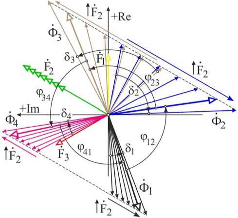
Fig. 4. Tuning vector diagram of toothed magnetic fluxes
Рис. 4. Регулировочная векторная диаграмма зубцовых магнитных потоков
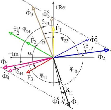
Fig. 5. Simplified vector magnetic fluxes diagram
Рис. 5. Упрощенная векторная диаграмма магнитных потоков
A study of the winding circuitry for three-, four- and six-zone machines with a triangle showed that, as a result of power transfer in an MHD machine, one of the phases of a three-phase transistor inverter, as a rule, is in the recovery mode [5; 9]. With technological reversals of the induction machine, taking into account the change in the phase sequence, the nature of the current distribution in the three-wire power cable changes so that in any phase the inductive power factor can become capacitive and vice versa. Nevertheless, in general, the nature of the asymmetry of the electromagnetic mode of the working body remains acceptable, and can be corrected using automated optimization procedures [18–20].
The conditionally optimal vectors are denoted by the symbols Ф 1 , Ф 2 , Ф 3 , Ф 4 (lines of increased fat content), but their distribution corresponds to almost twice the value of the magnetomotive force F 2 . The initial value of the magnetomotive force of all windings | k 1F1| = = | k 2 F 2 | = | k 3 F 3 | with the same shift α = π/3 there corresponds a more “curved" distribution of the vectors Фс1, Фс2, Фс3, Фс4, at which the amplitudes of the field vectors of the middle teeth are almost a quarter less than the amplitudes of the magnetic fluxes of the extreme teeth. Phase shift limits [δ 22 и δ 33 ] >> [δ 11 и δ 44 ], are obtained with an increase in the magnetomotive force of the middle, inverted phase from the value of F 2 , до FР 2.
The average position of the vectors Ф 1 , Ф 2 , Ф 3 , Ф 4 corresponds to the initially investigated distribution, fixed for the above diagrams (fig. 4, 5). The trajectories of the ends of the vectors without taking into account the dynamics of saturation remain linear, but are no longer parallel. Finding the points of the best location of the magnetic flux vectors is best performed iteratively using the means described in [9; 14; 21]. However, in this case, the equivalent optimal mode cannot be achieved, therefore, the best available mode is considered quasi-optimal.
Practical studies of prototypes of a six-zone induction machine have shown that the most “current curves” are turn-on circuits when connecting a single or double star with a neutral wire. And when switching to a circuit without neutral, there are so significant distortions of the symmetry in voltage that the efficiency of the middle windings of each group decreases unacceptably. By changing the linear current load of the windings, asymmetry can be damped to some extent, but in practice, traction efficiency, which is not comparable to a triangle, can be achieved. It should be noted that the search for the optimal ratio of the amplitudes of the magnetomotive force and phase shifts of the flows in several windings w 1 , w 2 , w 3 interconnected through a common magnetic field is the subject of numerical optimization, which is carried out for the characteristic circuit AZB of the phases of the induction machine.
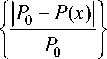
An example of a diagram of a family of magnetic flux vectors obtained by synchronous stepwise regulation of magnetomotive force sources F 1 , F 3 of the windings of the extreme phases for a three-zone inductor of the AZB circuit is shown in fig. 6. At the same time, the condition of invariance of the middle phase is provided |F 2 | = const.
Synchronous regulation of the magnetizing forces of the extreme windings F1 ↑↑ F3 и F1 ↓↓ F3 gives a picture of the distribution of magnetic fluxes Ф1, Ф2, Ф3, Ф4 with a significant distortion of symmetry and a change in the amplitude-phase relations between the vectors. For this method of regulating magnetizing forces, an optimization algorithm, that provides the best available solution, is also applicable
An example of the diagram of the magnetic flux vectors in the yoke, with fixed shifts α = π /3 and equal values of the magnetoresistance of the windings F1, F2, F3, is shown in fig. 7. This state corresponds to the previously obtained distribution of tooth magnetic fluxes Фс 1 , Фс 2 , Фс 3 , Фс 4 according to the vector diagrams of fig. 5, 6. In the diagram of fig. 7, the streams of teeth and the flows in the windings Фс Я1 , Фс Я2 , Фс Я3 placed on the yoke of the magnetic circuit are combined on a natural scale. In the analysis of diagrams, it must be remembered that the same notation is φ 12 , φ 23 , in fig. 5, 7 correspond to different angles.
One can see that, judging by the diagram, the equivalent phase zone of magnetic fluxes in the yoke occupies the raster angle (φ 12 + φ 23 ) < 2 α . Moreover, an increase in the linear current load in the middle of the core (magnetomotive force of the winding w2) leads to a narrowing of the equivalent phase zone with increasing phase shifts δ and in a significant, fraught with saturation, increase in the intensity of magnetic fluxes in the steel yoke. The ratio of the magnetic fluxes of the teeth (red vectors) and the fluxes in the yoke (green) shows a significant excess of the fluxes of the yoke over the fluxes of teeth oriented in the molten metal.
Essentially, this means that the inductor works with the molten metal on the scattering fluxes, and the main flow is directed along the core and consumes energy for heating steel, fastening metal structures and mechanical vibration. Nevertheless, the results of comparative mathematical modeling of inductors with longitudinal and transverse flow show that at a distance from the core by the size of the operating gap, the magnetic induction values of both inductors of the same size are comparable [15; 18]. The decrease in the efficiency of the cross flow inductors is due to the intense attenuation of the field in the melt. Therefore, the designs of shortened low-pole inductors of the longitudinal field turn out to be quite comparable in efficiency with a lower mass and greater manufacturability. The operating experience of cylindrical and flat induction machines of a longitudinal field showed that the energy of the scattering field at a frequency of 1 Hz, taking into account the presence of concentrators, is quite sufficient for effective impact on the melt within the calculated air gap.
The solution to the problem of achieving the optimal distribution of the magnetomotive force across the windings is carried out after modeling a multiphase magnetic circuit. For this, a well-known optimization technique using the genetic algorithm (GA) and local search modification is used [15; 16; 21]. In order to avoid obtaining a cumbersome intractable optimization problem, when studying the regulation of magnetomotive force, only a few parameters are selected and included in the objective function. The statement of the optimization problem is formulated in such a way that the greatest value of the pulling force for each concentrator is ensured with equal values of the serrated magnetic fluxes for a relatively equal distribution of field vectors in the raster, within the area of influence on the melt. As counteracting factors, the mass of copper of the induction windings and the loss of power for their heating are taken into account. The general expression for constructing the objective function in the selected optimization technique is shown below.
J| F - F ( x )| [ J| G - G ( x )| [
Fz(x) =n F ^ г + П G ^ 7, r + I FI I G I
[ Q - Q (% )| 1 [IR - R (% )| [
+ n QI —Q—l+nRI—R—Г...+
Л S - S ( x )| [ .
+ 4s)-------1 r ^ min.
I s I
F, G, Q, R, S are functions that significantly affect the aggregate objective function (1), if it is possible to take them into account in the problem at the programming stage, for example, by including subsystems with their description in the general computational algorithm of the project. First of all, these are the amplitudes and phases of the voltages, the overall dimensions of the induction machine, the mass and characteristics of materials, the geometry of the core and the parameters of the windings.
Taking into account the truncated goal of the study, the conditions for using software for the genetic algorithm should be limited. An abbreviated record of the expression of the objective function is shown below.
F z ( x ) =n F
1 1 F o - F ( % )| |
I F o I
+ Пф
Фо -Ф(%) ] ---------Г + П p
Фо [
^ min.
In the accepted notations, the symbol F ( x ) corresponds to the relative value of the magnetomotive force k 2 F 2 necessary to create an increased linear current load due to the middle winding, the symbol φ ( x ) is the phase shift φ 23 of the tooth magnetic flux vectors Ф 2 и Ф 3 , the symbol P (x) – relative value of active power in the winding, n k — weighting factors. Calculation in the genetic algorithm according to objective function (2) made it possible to identify the regime with the greatest effort, but at the same time the power and mass losses were somewhat overestimated in comparison with the results achieved at the design stage of the induction machine. At the same time, the obtained optimization results (fig. 8) for unequal magnetomotive force between the windings w 1 , w 2 , w 3 were confirmed at the stage of a numerical experiment for a sample of an MHD inductor of 5 tons in size according to option 1 (table), assigned for use on mixers with a working gap of about 500 mm.
Judging by the data obtained, for the given criteria: the range of change in the magnetomotive force k2F2 of the winding w2 and the phase shift φ23 (fig. 5) between the vectors of the tooth flows, the minimum of the objective function (2) and the greatest traction force are obtained when the linear current load increases to a value close to calculated, HМ = 89 kA/m and phase shift (Ф2^Ф3) equal to φ23 ≈ 76 degrees. The indicated value of the linear current load is achieved by increasing the base value of the magnetomotive force (F0 = 53 кА) of the second phase at point M (fig. 8) to F2M = w2.I2 = = kM ∙ F0 = 1,46 ∙ 53 = 78 кА. It should be noted that the development and refinement of the calculation algorithm for an extended list of optimized parameters of the induction MHD machine leads to a significant correction of the optimization project and even processing of the corresponding software. The generation of a mathematical model and its subsequent solution is not an easy task.
Objective function (1) is more complex in description and cumbersome to implement in terms of the effectiveness of achieving the result. In the considered model, it is not possible to take into account the cutting of iron sheets, the cost of cutting, the choice of the optimal tire section, etc., and therefore, the study should be considered simplified. To design a series of machines with improved technical and economic indicators, it is necessary to turn to the global algorithm and the results of a detailed study of a larger number of options. In this connection, only the results of the search for the best current distribution in the windings according to fig. 4, 5 are shown here, and detailed optimization of the MHD inductor modes in combination with a frequency inverter for an expanded list of requirements is highlighted in a separate project.
Structural-algorithmic synthesis of three-phase transistor IGBT inverters serves as a solution to the problem of constructing frequency inverters for the requirements of unbalanced load. The main way to control power switches is considered to be pulse-width program modules (PWM), which provide overmodulation and increase the level of output voltage. In practice, inverters use all the classic bridge structures with a two-stage high-voltage DC bus. The presence of a neutral point in the DC link provides bipolar power to the quasi-complementary output stage. In addition, such a structure allows us to propose circuit solutions that increase the stability of inverters when operating on an asymmetric load in a star [5; 8; 22]. In this case, the neutral points are connected, which serves as a means of balancing. However, such a balancing solution is unsuitable when connecting the induction MHD load to a triangle.
Taking into account the requirement of low cost of the power inverter as part of the MHD-mixing of the aluminum melt complexes, at the initial stage two-three-level inverting circuits, as well as matrix inverting circuits, are excluded from consideration of the options for constructing the inverting link. However, if there is a problem of power supply to a sharply asymmetric three-phase load in the steady state, it may be necessary to consider multi-level solutions. As shown in [5; 10], the asymmetry of the windings of induction MHD machines with inverted phases, in typical cases, can be accompanied not only by a change in the nature of reactivity, but also by a mutation of the electromagnetic mode. Moreover, the different phases of the inverter can go into recovery mode, due to the electromagnetic transfer of power between the windings of the induction device [3; 6].
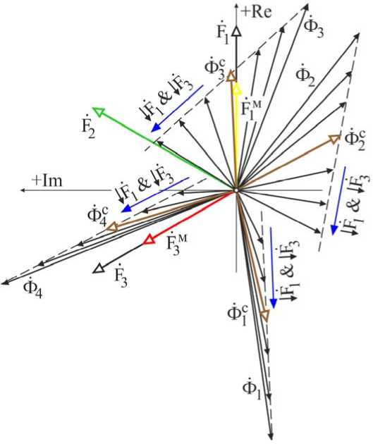
Fig. 6. Tuning vector diagram of magnetic fluxes
Рис. 6. Регулировочная диаграмма магнитных потоков
Fig. 7. Vector diagram of magnetic fluxes in yoke
Рис. 7. Векторная диаграмма потоков в ярме
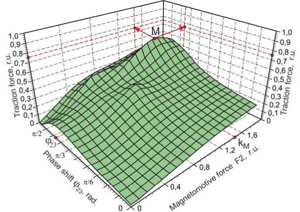
Fig. 8. Topology of the target function surface
Рис. 8. Топология поверхности целевой функции
According to the requirements of the technological mode of foundry and smelting equipment, the inverter must provide dynamic phase reversal, which complicates the task of constructing a stable multiphase power supply system for an induction MHD machine. An additional factor complicating the construction of the power supply system for shortened metallurgical induction machines is the preference for connecting a MHD inductor in a triangle. To balance the mode of standard half-bridge modules of different phases in the power link, it is possible to use an additional modular half-bridge, which in the specified order is connected to the load as a means of balancing [10; 22]. Such a connection can be considered as one of the options for the parallel connection of IGBT modules, valid for single-level three-phase inverters.
The described features of the current distribution in the windings and phases of the MHD machine create the conditions for considering a wider range of circuit and algorithmic solutions in the structure of the IGBT inverter [5; 8; 22]. It is possible to find a solution by duplicating the half-bridge of each phase with an additional power rack with their parallel coordinated inclusion. In addition, it is necessary to take into account the need for extreme dumping of large reactive capacities during an emergency shutdown of the MHD inductor. This is very significant, since a standard power utilization unit is provided in the structure of a standard frequency converter. For the changed operating conditions, the modes of its operation under sharply asymmetric load should be firmly entered into the inverter state control algorithm, since this determines the reliability of the entire complex of MHD-mixing of the melt. The above, formalized in the transition from general considerations to the formation of a set of requirements, in the form of technical specifications for the development of a PWM inverter.
Conclusion. Induction MHD machines of a longitudinal magnetic field, designed to mix the melts, have different tooth intensity in the melt. Therefore, to correct the running magnetic field mode, the linear current load of the inductor and the phase mode of the inverter are used. Of practical importance is the method of adjusting the flow distribution by coordinating the calculated number of turns in the induction windings, with the distribution of currents over the phases of the frequency converter. The required value of the magnetomotive forces of the windings of each phase is specified by adjusting characteristics at the stage of modeling and optimization of the MHD machine. In addition, to adjust the characteristics of the induction MHD machine, program-algorithmic control of the amplitude-phase operating parameters of the inverter is used, which makes it possible to equalize the distribution of tooth magnetic fluxes and the traction value in the melt. With any distribution of magnetic fluxes along the teeth, the intensity of the magnetic field in the magnetic circuit exceeds the intensity of the tooth components. This can be considered a drawback of the considered construction of MHD machines with a longitudinal magnetic field, since an increased value of the magnetic induction in the yoke can lead to premature saturation of the core, distortion of the currents in the windings and a decrease in the efficiency of the inverter of the power source. Taking into account the low-polar nature of the induction machine, it can be noted that at a distance of the working gap, the magnetic field intensity is leveled out and is sufficient to effectively influence the melt. The considered example of optimization of the electromagnetic characteristics of the MI additionally improves the operational properties of induction MHD machines of a longitudinal magnetic field.
References Approach to optimization of the magnetic circuit of a three-phase induction plant
- Tyapin A. A. The structure of electromagnetic stirrers. Znanstvena Misel Journal. 2018, No. 20-1, P. 50–57.
- Tyapin A., Kinev E. Electromagnetic mode of the MHD machine when connected by a star with winding switching. Osterreichisches Multiscience Journal. 2019, Vol. 1, No. 16, P. 35–43.
- Tyapin A. A. Three-phase induction machine of a three-zone design for MHD stirrer. The scientific heritage. 2019, Vol. 1, No. 34, P. 57–65.
- Chaplygin E. E. [Asymmetrical modes of a threephase converter with power factor correction]. Elektrichestvo. 2005, No. 9, P. 55–62 (In Russ.).
- Kinev E. S., Tyapin A. A. [Circuitry connecting IGBT-inverter to a multi-phase induction machine]. Cb. nauch. tr. II Mezhdunarod. nauch.-praktich. konf “SAPR i modelirovanie v sovremennoy elektronike” [Collection of scientific papers of the II International Scientific and Practical Conference “CAD and modeling in modern electronics”]. Bryansk, BSTU, 2018. Part 1, P. 208–215. Doi: 10.30987/conferencearticle_5c19e61d557532.76134464.
- Vol'dek A. I. [The distortion of the symmetry of the voltages and currents in induction machines with an open magnetic circuit]. Izvestiya vuzov. Elektromekhanika. 1960, No. 5, P. 78 (In Russ.).
- Belitsky A. A., Shklyarsky Ya. E. [Estimation of additional power losses in electrical networks with nonlinear and asymmetric load]. Izvestiya TulGTU. Tekhnicheskie nauki. 2018, Iss. 7, P. 86–93 (In Russ.).
- Mytsyk G. S., Hlaing Min U. [Three-phase voltage inverters, insensitive to load unbalance]. Vestnik MEI. 2016, No. 4, P. 62–68 (In Russ.).
- Kinev E. S., Tyapin A. A., Yefimov S. N. [Assessment of the asymmetry of the induction machine with the parameters of symmetrical components]. Vestnik Voronezhskogo gos tekhn. un-ta. 2018, Vol. 14, No. 6, P. 68–79 (In Russ.).
- Chaplygin E. E. Vilkov A. E., Hukhtikov S. V. [Pulse-width modulation with a passive phase in tension inverters with the additional halfbridge]. Elektrichestvo. 2012, No. 8, P. 53–61 (In Russ.).
- Bartenev O. V. Sovremennyy Fortran [Modern Fortran]. Moscow, Dialog-Mepi Publ., 2000, 449 p.
- Morozov E. A. Muyzemnek A. Yu., Shadsky A. S. ANSYS v rukakh inzhenera [ANSYS in the engineer's hands]. Moscow, Lenand Publ., 2018, 456 p.
- Raj C. T., Srivastava S. P., Agarwal P. Energy Efficient Control of Three-Phase Induction Motor – A Review. International Journal of Computer and Electrical Engineering. 2009, Vol. 1, No. 1, P. 61–70.
- Sarapulov F. N., Sarapulov S. F., Shymchak P. Matematicheskie modeli lineynykh induktsionnykh mashin na osnove skhem zameshcheniya [Mathematical models of linear induction machines on the basis of equivalent circuits]. Yekaterinburg, GOU VPO UGTU-UPI Publ., 2005, 431 p.
- Golovenko E. A., Goremykin V. A. Kinev, E. S., Gudkov I. S., Bezhitskiy S. S. [Criteria for selection of design solutions for optimal short-pole linear induction machines]. Vestnik SibGAU. 2013, No. 1 (47), P. 142–146 (In Russ.).
- Palko S. Structural Optimisation of an Induction Motor using a Genetic Algorithm and a Finite Element Method. Acta Polytechnica Scandinavica. Electrical Engineering Series. 1996, No. 84, P. 99.
- Hassanpour I. A., Ebrahimi B. M., Lesani H. Design Optimization of a Low-Speed Single-Sided Linear Induction Motor for Improved Efficiency and Power Factor. IEEE Transactions on Magnetics. 2008, Vol. 44, No. 2, P. 266–272.
- Tyapin A. A. Optimization of the magnetic circuit of a three-phase induction device. Danish Scientific Journal. 2019, Vol. 1, No. 21, P. 60–68.
- Cunkas M., Akkaya R. Design optimization of induction motor by genetic algorithm and comparison with existing motor. Mathematical and Computational Applications. 2006, Vol. 11, No. 3, P. 193–203.
- Pant M., Thangaraj R., Singh V. P. Efficiency optimization of electric motors: a comparative study of stochastic algorithms. World Journal of Modelling and Simulation. 2008. Vol. 4, No. 2, P. 140–148.
- Bezhitskiy S. S., Golovenko E. A., Goremykin V. A., Pervukhin M. V. [On the solution of the problem of optimal selection of the power parameters of a linear induction machine by a genetic algorithm with local search]. Vestnik SibGAU. 2010, No. 4 (30), P. 23–27 (In Russ.).
- Berbenec A. [Control of parallel connection of IGBT modules. CT-Concept Plug & Play Drivers]. Silovaya elektronika. 2012, No. 4, P. 40–44 (In Russ.).
