ASIC Implementation of Finger Print Recognition Using Overlap-Add and Integer Wavelet Transform Methods

Author: Shashidhara H. R, Aswatha A. R
Journal: International Journal of Image, Graphics and Signal Processing(IJIGSP) @ijigsp
Article in issue: 7 vol.9, 2017.
Free access
The field of fraud identification is reaching a very high proportion in the society, thus leading to an increase in the need for fingerprint-based identification. This paper presents ASIC implementation of fingerprint recognition based on Overlap-add method and Integer Wavelet Transforms. In overlap-add method, the present output overlaps the next output and in the integer to integer wavelet, low component at 2nd level decomposition is taken as approximate integer value. The implementation presents an analysis for speed, area and power dissipation between the two algorithms and other methods.
Biometrics, Fingerprint Identification, Overlap-add Method, Integer Wavelet Transform, ApplicationSpecific Integrated Circuits
Short address: https://sciup.org/15014203
IDR: 15014203
Text of the scientific article ASIC Implementation of Finger Print Recognition Using Overlap-Add and Integer Wavelet Transform Methods
Published Online July 2017 in MECS DOI: 10.5815/ijigsp.2017.07.04
Biometrics is the science and technology of analyzing and measure biological data. Biometric methods of identification are referred to traditional methods mainly for two reasons:
-
• At the time of verification, the physical presence of the identifying person is required.
-
• Identification based on biometrics avoids the need to remember the password or carrying a token.
Fingerprints, palm-print, Iris etc., are some types of biometrics based method to identify individual person to verify their identity. Fingerprint recognition is the most reliable method for person identification and plays an important role in criminal investigation, terrorist identification and national security issues. The impression of the fingerprint contains friction ridges. They are, unique in nature, detailed, difficult to alter and durable for the life span of human being. Fingerprint recognition refers to the automated method of verifying a match between human fingerprints.
The analysis and study of fingerprints for matching compares the several print pattern features. This fingerprint contains patterns like ridges and minutia points, which are unique features of patterns. A fingerprint is represented by location, types, and some attributes like angle of inclination of minutiae etc., are shown in Fig 1. One hundred years of study on fingerprints ensures the uniqueness of minutiae based representation for a very large population in the world. To establish the identity, 50 to 150 minutiae’s are enough but in automated systems 10 matching minutiae are assumed to be sufficient.
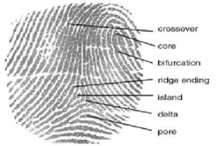
Fig.1. Fingerprint Features
-
II. Related Work
One of the previous methods for fingerprint identification is Henry Classification System [1], which creates the primary groupings based on fingerprint pattern types from the logical categorization of ten-print fingerprint records. Over the years, Principal Component Analysis (PCA) was an efficient approach in the pattern recognition [2]. This approach effectively extracts the global features from the aligned fingerprint images. PCA transforms a number of correlated variables into uncorrelated variables known as principal components.
Anil K. Jain [3] in his paper has proposed filter bank based algorithm for fingerprint recognition. Gabor filters are used to consider the global and local details of fingerprint. Anil K. Jain, et. al,[4] have proposed a method on the combination of different fingerprint matching algorithms to develop the performance of a Finger Print Recognition (FPR) system. In this paper they have combined the scores values from logistic transform, which are generated from three dissimilar fingerprint matching algorithms. Arun Ross, Anil K Jain and Salil Prabhakar [5] have proposed fingerprint matching using minutiae and texture features. F. G. Hashad, et. al. [7] have introduced Mel Frequency Cepstral Coefficients (MFCCs) for Fingerprint Recognition. Manisha Redhuand and Dr.Balkishnan [9] has proposed new method in FPR system. They used score values obtained from matching method and image enhancement is done by using histogram technique and FFT. S. Gayathri and Dr. V.Sridhar [12] have shown the ASIC implementation of fingerprint recognition process. The efficiency of the fingerprint recognition system depends on the minutiae obtained from the unprocessed image.
The objective of this paper is to design a high speed, low area based fingerprint recognition system, which can process every fingerprint image of the user. The finger print identification has been implemented by using two algorithms: they are Fast Convolution and Integer Wavelet Transforms. The fast-convolution method uses overlap add method than overlap save method, because overlap save method saves previous stage outputs, thus requiring huge memory. In the overlap add method the previous stage is not saved and hence memory requirement will be less. The integer wavelet is a 2nd level transformation technique to transform the low order coefficient in the time-frequency domain. With an On-chip architecture being developed for a high speed and low area FPR system, the designed system is verified as an IP for Functionality and Performance. The rest of the paper is organized with Section II describing the overlapadd method and IWT algorithm used. Section III presents simulation results and performance evaluation of the systems. Section V gives the conclusion for the paper.
-
III. Methodology
The flow diagram shown in the Fig 2 explains general process of fingerprint recognition. The thresholding/binarization and skeletonisation are the preprocessing steps and feature extractions are common to both the algorithms. Features of fingers are extracted using fast convolution and IWT method after which, bit wise matching is done using hamming distance.
-
A . Thresholding/Binarisation
In fingerprint image the foreground have high grey value and the background regions exhibit a low grey- scale value. Hence in thresholding is performed based on threshold values. First, the image is divided into number of blocks and for each block grey-scale mean is calculated. If the grey value (Gi) of a particular pixel is less than the mean of that block (Bi), then zero is assigned otherwise one is assigned. The outcome of this process is shown in Fig 3, is a binary image having two levels of information.
I(x; y) = 0; if Gi < Bi; = 1; otherwise; (1)
-
B. Skeletonisation
Skeletonisation of binary images is done by a process called thinning that reduces all lines to a single pixel thickness. Thinning algorithm retains the connectivity of ridge structures while forming a skeletonised finger image. To eliminate a pixel the following conditions must be considered:
-
• The pixel will not be reasoned as an endpoint.
-
• The elimination of pixel does not break
connections of the skeleton.
-
• The elimination does not cause excessive erosion of the region.
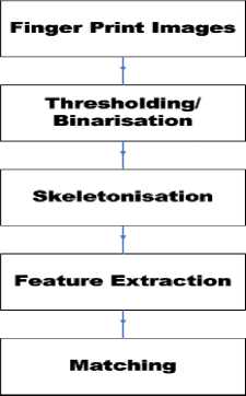
Fig.2. Flow Diagram for Fingerprint Recognition
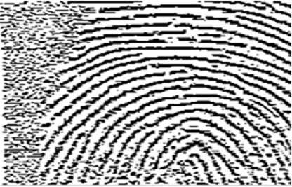
Fig.3. Binarized Image
In the Fig 4 is the skeletonized image used in the subsequent extraction of minutiae. After Skeletonisation the features like ridges, delta points are extracted using Overlap-add and IWT method, as explained in the following sections.
-
C. Feature Extraction
-
i. Overlap add method
The overlap-add method is a type of convolution for fixed coefficients and it is computationally efficient but requires more memory. This method can be applied to frequency domain and time domain using DFT and IDFT techniques. In basic convolution technique, after the multiplication the output values are added. The final output will be very long sequence, to computation of these long sequence is very difficult. In overlap add method the output from the rear end of the former block is overlapped with the front end of the present block. The process of overlapping and addition of the convoluted signal is carried out. Hence the name overlap-add method. In this work overlap add method is used for feature extraction. The Fig 5 shows overlap-add method procedure, the input signal is f and it is split into small signal. Then it is convoluted with the kernel g. Each convoluted blocks are overlapped and then added. Finally we get the convoluted sequence. The length of this sequence obtained is less than the basic convolution method.
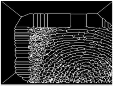
Fig.4. Skeletonized Image
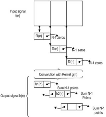
Fig.5. Overlap add method
First the input signal f is split into smaller disjoint tiles f1; f2; ::; fm. Therefore f(n) = f1(n) + f2(n) + :. For the computation of convolution the selected signal f i and the large kernel g is considered. That is,
h(n) = f(n)*g(n); f(n) = f1(n)+f2(n)+f3(n)+::::f (n)*g(n) = (f1(n)+f2(n)+f3(n)+::::)*g(n)h(n) (2)
Let us consider a input block of size L points and the size of DFT and IDFT will be N = L+M-1. To compute N point DFT concatenate each block with M-1 zeros. Therefore the data block will be, x1(n) = x(0); x(1); ; x(L-1); 0; 0; :; 0x2(n) = x(L);
x(L+ 1); ; x(2L-1); 0; 0; :; 0x3(n) (3)
Therefore 2N point DFT is,
Y m (k) = H(k)X m (k) k = 0; 1; ::;N-1 (4)
That is,
Y (n) = y1(0); y1(1); :y1(L-1); y1(L) + y2(0);
y1(L + 1) + y2(1); ::; y1(N-1) + y2(M-1); y2(M); (5)
-
• Add the impulse response K i with N zeros in window g & transform to frequency domain with K l (m) with l=0,1,. . . , 2N-1, follows for every iteration m=0,1,2,. . .
-
• Choose N samples from signal x(m) and add these by N zeros in segment to produce a block
-
• Transform to frequency domain which results in the frequency bins X l (m) with l=0, 1, .2N-1.
-
• Convolute X l (m) & W l (m) for l=0, ....2N-1.
-
• Transform back convoluted values to time domain using IDFT e i (m) with i=0, 1,....2N-1.
-
• Perform desegmentation to generate the output signal with k=mN+I calculated as The algorithm of overlap add method is,
-
• Break the input signal f (n) into non-overlapping blocks f m (n) of length L.
-
• Pad zero for g(n) to be of length N = L + M - 1.
-
• Take N-DFT of g(n) to give G(k), k = 0,1,. . .N-1.
-
• For each block m:
o Zero pad fm(n) to be of length N = L + M -1.
o Take N-DFT of fm(n) to give Fm(k), k = 0,1,N -1.
o Multiply: H m (k) = F m (k) * G(k), k =
0,1,N -1.
o Take N-IDFT of Hm(k) to give Hm(n), n = 0,1,N -1.
-
• Form h(n) by overlapping the last M -1 samples of hm(n) with the rest M -1 samples of hm+1(n).
-
• The adding overlapped samples of hm(n) and h m +1(n).
-
• The 5 DFT overlap add method is shown in Fig 6.
Fig 6 Overlap Add Method with 5 DFTs in frequency domain.
-
ii. Integer wavelet transform
The second algorithm is used to extract the finger image feature is Integer Wavelet Transform (IWT). The disadvantage of DWT is that it contains real numbers as wavelet coefficients. So efficient lossless coding is not possible using linear transforms. The lifting scheme (LS) is an efficient implementation of the DWT and also perfect reconstruction is ensured. This creates new transformation, like integer wavelet transform (IWT). IWT is a basic modification of linear transforms, in which output is rounded to the nearest integer. It is also of interest for hardware implementations, where the use of floating point is still a costly operation.
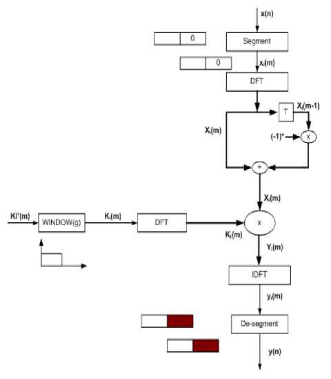
Fig.6. Overlap add method
The convolution based DWT needs a large number of arithmetic computations and a large memory for storage. The IWT requires fewer computations compared to the convolution based DWT. In IWT the computational complexity is reduced to almost a half as compared to convolution approach.
The main advantages are as follows:
-
• It consents to a faster implementation.
-
• It permits fully in place calculation, in other words, no auxiliary memory is needed and the original signal (image) can be replaced with its wavelet transform.
-
• By reversing the operations, the inverse wavelet transform is created.
There are several frameworks are explained, in that most popular are S+P, Lifting scheme and overlapping rounding transform (ORT) frameworks. The S-transform is the most basic framework for ITI transform. The below section briefly describes the S-transform for the basics of ITI and also other three frameworks which are generally used.
S-Transform: The Sequential (S) transform is uncomplicated and ubiquitous ITI transform. The S transform is the approximated (linear) Haar transform of ITI and is allied with UMD filter bank as shown in Fig 7. The forward and inverse transform is calculated by the analysis and synthesis side of the filter bank respectively as shown in Fig 7. The mathematical analysis of the S-transform is given by,
Y 0 [n]=[1/2(x[2n]+x[2n+1])] (6)
and
Y 1 [n]=[1/2(x[2n]-x[2n+1])] (7)
Where the forward transform divides the input signal x[n] into low y 0 [n] and high y 1 [n] pass components. The above forward transform are considered for infinite length and for finite length the symmetric and periodic extension can be considered. The S-transform shows two key remarks, first any two coefficient values are calculated from their sum and difference. Second, the sum and difference of any two coefficients have same parity (which omits the fractional part without losing information).
S+P transform : This transform is known as sequential plus prediction, it is a direct extension of S-transform. The framework of S+P transform is shown in Fig 7, mathematically it can be expressed as
Y0 [n]=[1/2(x[2n]+x[2n+1])](8)
and
Y1 [n]=[v_0[n]-[t[n]+1/2]](9)
y0 [n]=[1/2(x[2n]-x[2n+1])](10)
and
L 0 , L 1 and K are integers satisfying L 0 ≤ L 1 and K≤ 1.
The forward transform divides the input coefficients x[n] into low-pass and high-pass coefficients as y 0 [n] and y1[n] respectively.
From the above equations, it is found that the S+P transform is generated by adding an extra step to S-transform; that is the high-pass component of S-transform is adjusted with an extra prediction operation. The predictor component α i and β i is shown in table 1.
Table 1. Predictor Co-efficient
|
Predictor |
α -1 |
α 0 |
α 1 |
β -1 |
|
A |
1/4 |
1/4 |
0 |
0 |
|
B |
3/8 |
2/8 |
0 |
0 |
|
C |
8/16 |
4/16 |
1/16 |
6/16 |
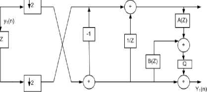
Fig.7. S+P transform with UMD filter bank
Lifting framework : The most popular framework of ITI transform is based on the lifting scheme. The lifting framework is a polyphase comprehension of UMD filter banks, which adopts ladder networks for filtering. The 1-D two channel UMD filter bank contains 2 steps, they are lifting and scaling steps. In lifting step, the filters A k is constituted and in scaling step the amplifiers of gain s k as shown in Fig 8.
The ladder network of lifting scheme has to sustain their invariability even for quantization error (rounding error by finite precision arithmetic). The construction of lifting scheme based ITI transform follows initially to constrict the lifting scheme, eliminate the scaling function having a non-integer gain factor, and then transforms each lifting step to the rounding operation Q at the output of its corresponding filter as shown in Fig 8.
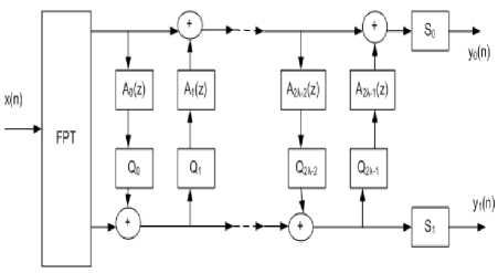
Fig.8. Lifting framework with UMD filter bank
Overlapping Rounding Transform: Overlapping Rounding Transform (ORT) framework is a polyphase apprehension of UMD filter bank. The Fig 9 shows the forward transform of 1-D two channel UMD filter bank. The cascade of two input two outputs ITI networks is performed from polyphase filtering.
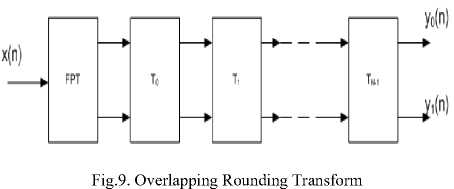
Finger features are extracted by using the lifting scheme based ITI transform.
-
D. Minutiae Reduction
Minutiae are the trivial details of fingerprint. An unavoidable source of error in fingerprint recognition is false minutiae. These are inevitable because of distortion such as scars, sweat, etc. Existence of false minutiae forces the matching process to fail. It is possible to handle excessive numbers of them; therefore after the feature extraction phase, the minutiae list is analyzed to eliminate false minutiae. Our approach is to eliminate minutiae features using distance criteria, e.g., minutiae which are too close to each other are discarded. For a particular minutiae point within the D8 distance (also called as chessboard distance), only one minutia point is considered. Any other minutiae point existing within of 3 are all eliminated.
-
E. Matching using Hamming Distance
The Hamming distance between two strings of equal length is calculated by creating a sequence of logical Boolean values indicating matches and mismatches between their position in the two inputs, and then summing the sequence.
I(x,y)=I(x i ,y i ) xor I(x j ,y j ) (11)
-
IV. Result
The inputs which are described in the modules are functionally verified using ModelSim. After the successful completion of simulation, the design is synthesized using Cadence tool.
-
A. Fast Convolution Method
Fig 10 shows the top module of Overlap-add Method, if the test image is matched with the reference image. It shows the end point branch points and matching score.
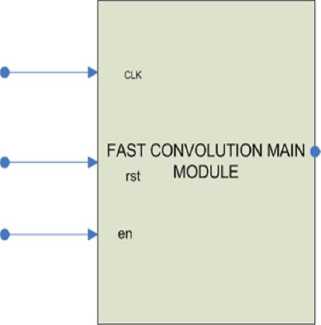
Fig.10. Finger Print Top Module for overlap add method
MATCH
Table 2 describes the signal details of the top module.
Table 2. Signal Description of Top Level Module.
|
Signal |
I/O |
Description |
|
CLK |
Input |
Synchronous clock signal of finger print top module |
|
rst |
Input |
Reset signal |
|
en |
Input |
Enable signal |
|
MATCH |
Output |
The final authentication match signal |
Table 2 describes the signal details of the top module. The simulation results for the finger print top module are given in Fig 11 and Fig 12. In this module the two finger images are obtained from the text file. All these data are of eight bit in nature. The module operates for the positive edge of clk and rst=0. Initially when the clk signal is at the positive edge and rst=1, no data evaluation process is taking place as shown in Fig 11 and Fig 12. Fig 11 shows the unmatched condition if the test image does not match with the reference image. It shows that fingerprint is not identified.
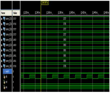
Fig.11. Simulation Results for Unmatched Condition
In Fig 12 the matched condition is shown, when both the test and reference finger images are same, the match signal is 1.
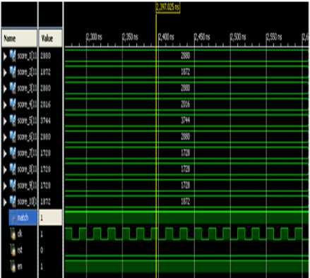
Fig.12. Simulation Results for Matched Condition
The resultant cell layout is shown in Fig 13. The Table 3 and Table 4 describe the memory usage and power utilization before routing. The total area of 9100.560µm2, the total power 444030.394nW and total cells of 1496 in that sequential gate of 1211 and the logic gate count of 743.
Table 3. Area Utilization Summary of overlap add Method
|
Instance |
No. of Cells |
Cell Area |
|
Sequential |
1211 |
8036.582µm2 |
|
Inverter |
212 |
212.420 µm2 |
|
Logic |
743 |
851.558 µm2 |
|
Total Area |
1496 |
9100.560 µm2 |
Table 4. Power Utilization Summary of overlap add Method
|
Leakage Power |
291.522 nW |
|
Dynamic Power |
443738.872 nW |
|
Total power |
444030.394 nW |
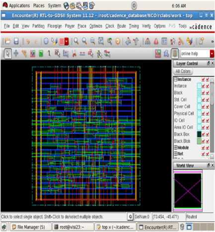
Fig 13. Final routed Cell layout of the overlap add Method
-
B. Integer Wavelet Transform
The top module of Integer Wavelet Transform as shown in Fig 14. Table 5 describes the signal details of this top module.
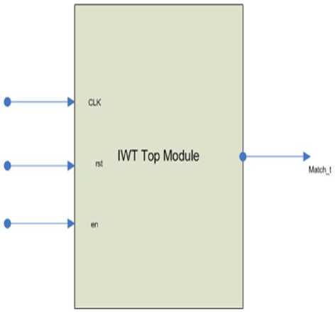
Fig.14. Finger Print Top Module for Integer Wavelet method
Table 5. Signal Description of IWT Top Level Module
|
Signal |
I/O |
Description |
|
CLK |
Input |
Synchronous clock signal of finger print top module |
|
rst |
Input |
Reset signal |
|
en |
Input |
Enable signal |
|
Match_t |
Output |
The final authentication match signal |
The simulation results for the finger print top module are shown in Fig 15 and Fig 16. The module operates for positive edge of clk and rst signal i.e, when rst is 1 the data is considered else the module resets to zero. Fig 15 shows the unmatched condition if the test image does not match with the reference image. It shows that fingerprint is not identified with match as zero.
In Fig 16 the matched condition is shown, when both the test and reference finger images are same, the match signal goes to 1.
The cell layout as shown in Fig 17 and Table 6 and Table 7 shows the area and power dissipation of IWT based finger print module. The total area of 53271 µm2 having 8752, sequential cells of 912 has 23701.104 µm2 of area, the inverter having 158 cells and 334 µm2 area. The total power dissipation of 388021.953nW in that leakage power of 285.735nW and dynamic power 387736.218nW. Table 8 shows the area, number of cells and gates after detailed routing.

Fig.15. Simulation Results for No-Match Condition
Table 8 shows the comparative study of IWT, Overlapadd, O2D and Image enhancement technique compared between area, gate count, power dissipation and delay. The IWT technique shows better performance with respect to area, power and gate count. Fig 18 shows the comparative study of recognition rate between IWT and Overlap-add technique, IWT shows higher recognition rate than Overlap-add method.
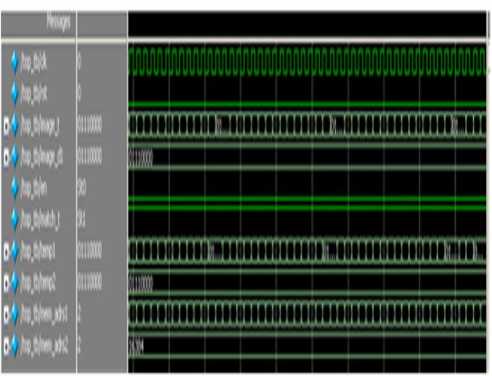
Fig.16. Simulation Results for Match Condition
Table 6. Area Utilization Summary of Integer Wavelet Method
|
Instance |
No. of Cells |
Cell Area |
|
Sequential |
912 |
23701.104µm2 |
|
Inverter |
158 |
334.454 µm2 |
|
Logic |
682 |
20235.125 µm2 |
|
Total Area |
1752 |
44270.683 µm2 |
Table 7. Power Utilization Summary of Integer Wavelet Method
|
Leakage Power |
285.735 nW |
|
Dynamic Power |
387736.218 nW |
|
Total power |
388021.953 nW |
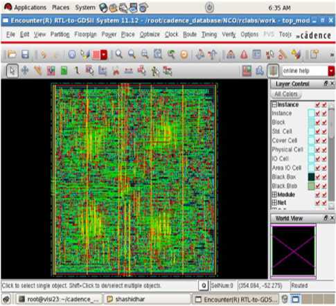
Fig.17. Final routed Cell layout of the Integer wavelet Design
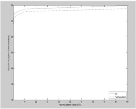
Fig.18. GAR vs FAR of overlap add and IWT
-
V. Concusion
The comparative study reveals that IWT is highly efficient compared to overlap-add Method, Image enhancement technique and O2D. The characteristics of low area, low power and low delay for IWT is shown through the ASIC Implementation of the same. It has been observed that the recognition rate of IWT is better than overlap-add method. The credibility to use both algorithms has been justified with improved recognition rate, area, power and delay, compared to other algorithms. In future, only those features in the required region of the finger can be concentrated upon and can be derived for higher recognition rate and effective ASIC implementation.
Table 8. Comparison of device parameters between different algorithms
|
Overlap- Add |
IWT |
O2D[16] |
Image Enhancement [12] |
||
|
Technology/FPGA |
Tsmc18.1.0 |
Tsmc18.1.0 |
Vertex-xc5vlx110t |
Tsmc18.1.0 |
|
|
Area/LUT/Register-FF |
8888.141 µm2 |
6852.2 µm2 |
94521 |
70242.49 µm2 |
|
|
Gates |
Sequential |
1211 |
912 |
--- |
1744 |
|
Unresolved |
212 |
158 |
--- |
414 |
|
|
Logic |
743 |
682 |
--- |
6183 |
|
|
Delay/Speed |
1565ps |
1032ps |
56.686MHz (Clock rate) |
--- |
|
Anil Jain, Arun Ross and Salil Prabhakar, “Fingerprint matching using minutiae and texture features”, Appeared in Proc. of Int’l Conference on Image Processing (ICIP), Thessaloniki, Greece, Oct 7 - 10, 2001, pp.282-285.
Wang Yongxu, Ao Xinyu, Du Yuanfeng and Li Yongping, “A Fingerprint Recognition Algorithm Based on Principal Component Analysis”, 2006 IEEE Region 10 Conference (TENCON 2006), pp.1-4.
Ramandeep Kaur, Parvinder S. Sandhu, and Amit Kamra, “A novel method for fingerprint feature extraction”, Proc. IEEE International Conference on. Networking and Information Technology, 2010, pp.1-5.
Manisha Redhu and Dr.Balkishan, “Fingerprint Recognition Using Minutiae Extractor”, International
Journal of Engineering Research and Applications (IJERA) ISSN: 2248-9622, Volume 3, Issue 4, 2013, pp.2488-2497.
Signal Processing(IJIGSP), Vol.9, No.2, pp.9-18,
-
[20] Iwasokun Gabriel Babatunde, “Fingerprint Matching Using Minutiae-Singular Points Network”, International Journal of Signal Processing, Image Processing and Pattern Recognition”, Volume 8, Issue 2, 2015, pp.375388.

References ASIC Implementation of Finger Print Recognition Using Overlap-Add and Integer Wavelet Transform Methods
- Cheong Hee and Haesun Park, “Fingerprint classification using fast Fourier transform and nonlinear discriminant analysis”, Journal of Pattern Recognition, Elsiever, 2005, Volume 38, Issue 4, pp.495-503.
- M. Kawagoe and A. Tojo, “Fingerprint Pattern Classification”, Pattern Recognition, Volume 17, Issue 3, 1984, pp.295-303
- Anil K. Jain, Salil Prabhakar, Lin Hong, and Sharath Pankanti, “Filter bank-Based Fingerprint Matching”, IEEE Transactions on Image processing, Volume 9, Issue 5, 2000, pp.846-859
- Anil K.Jain, Salil Prabhakar and Shaoyun Chen, “Combining multiple matchers for a high security fingerprint verification system”, Pattern Recognition Letters, Elsivier, 1999, Volume 20,Issue 11, pp.1371-1379.
- Anil Jain, Arun Ross and Salil Prabhakar, “Fingerprint matching using minutiae and texture features”, Appeared in Proc. of Int’l Conference on Image Processing (ICIP), Thessaloniki, Greece, Oct 7 - 10, 2001, pp.282-285.
- Wang Yongxu, Ao Xinyu, Du Yuanfeng and Li Yongping, “A Fingerprint Recognition Algorithm Based on Principal Component Analysis”, 2006 IEEE Region 10 Conference (TENCON 2006), pp.1-4.
- Hashad, F. G., “A new approach for fingerprint recognition based on Mel frequency cepstral coefficients”, Proc. IEEE International Conference on Computer Engineering \& Systems, 2009, pp.263-268.
- Ramandeep Kaur, Parvinder S. Sandhu, and Amit Kamra, “A novel method for fingerprint feature extraction”, Proc. IEEE International Conference on. Networking and Information Technology, 2010, pp.1-5.
- Manisha Redhu and Dr.Balkishan, “Fingerprint Recognition Using Minutiae Extractor”, International Journal of Engineering Research and Applications (IJERA) ISSN: 2248-9622, Volume 3, Issue 4, 2013, pp.2488-2497.
- Ajit Kumar, and Cyril Kwong, “Towards contactless, low-cost and accurate 3D fingerprint identification”, IEEE Transactions on Pattern Analysis and Machine Intelligence, Volume 37, Issue 3, 2015, pp.681-696.
- M. Kamaraju and P. A. Kumar, “DSP based embedded fingerprint recognition system”, Proc. IEEE 13th International Conference on In Hybrid Intelligent Systems (HIS), 2013, pp.6-11.
- S. Gayathri and Dr. V.Sridhar, “ASIC Implementation of Image Enhancement Technique for Fingerprint Recognition Process:, Proc. International Conference on Contemporary Computing and Informatics, 2014, pp.868-873.
- S. Santhosh, “Design and development of a security module with inbuilt neural network methodologies and an advanced technique on fingerprint recognition”, IEEE International Conference on Circuit, Power and Computing Technologies, 2014, pp. 1490-1495.
- Fred Kaggwa, John Ngubiri and Florence Tushabe, “Evaluation of multiple enrollment for fingerprint recognition”, IEEE Global Summit on Computer \& Information Technology, 2014, pp.1-6.
- BinduGarg, ArjunChaudhary, KunalMendiratta and Vijay Kumar, “Fingerprint Recognition Using Gabor Filter”, International Conference on Computing for Sustainable Global Development (INDIACom), 2014, DOI: 10.1109/IndiaCom.2014.6828105.
- Satish S Bhairannawar, SayantamSarkar, Raja K B and Venugopal K R, “An Efficient VLSI Architecture for Fingerprint Recognition using O2D-DWT Architecture and Modified CORDIC-FFT”, IEEE International Conference on Signal Processing, Informatics, Communication and Energy Systems (SPICES 2015), Kozhikode (Calicut), India, 2015, pp.193-197.
- Om Preeti Chaurasia, Saumya Ranjan Giri, Anchal Garg, "A Novel Algorithm for Minutiae Matching", International Journal of Image, Graphics and Signal Processing(IJIGSP), Vol.4, No.3, pp.8-14, 2012.DOI: 10.5815/ijigsp.2012.03.02.
- Jyoti Malik,Dhiraj Girdhar,Ratna Dahiya,G. Sainarayanan,"Reference Threshold Calculation for Biometric Authentication", IJIGSP, vol.6, no.2, pp.46-53, 2014.DOI: 10.5815/ijigsp.2014.02.06
- Shiv Gehlot, John Deva Kumar,"The Image Segmentation Techniques", International Journal of Image, Graphics and Signal Processing(IJIGSP), Vol.9, No.2, pp.9-18, 2017.DOI: 10.5815/ijigsp.2017.02.02
- Iwasokun Gabriel Babatunde, “Fingerprint Matching Using Minutiae-Singular Points Network”, International Journal of Signal Processing, Image Processing and Pattern Recognition”, Volume 8, Issue 2, 2015, pp.375-388.
