Asymmetric invariant echo-jack of the second order without a protective time interval and its characteristics

Author: Malinkin V.B., Kulyasov E.V., Malinkin E.V., Pavlov I.I.
Journal: Сибирский аэрокосмический журнал @vestnik-sibsau
Section: Математика, механика, информатика
Article in issue: 5 (26), 2009.
Free access
The structure of the invariant echo-jack of the second order without a protective time interval is synthesized. Control elements of such echo-jack are given. The calculation of the basic technical characteristics is presented.
Invariant, an echo-jack, asymmetric, echo-compensator, power of self-noise
Short address: https://sciup.org/148176065
IDR: 148176065
Text of the scientific article Asymmetric invariant echo-jack of the second order without a protective time interval and its characteristics
Themaintelecommunicationnetworkuses, inoverwhelming majority of cases, fiber-optical transmission systems. However the standard streams often don’t reach the consumer because of the «last mile», presented by a copper cable.
Existing modern high-speed technologies of access use xDSL adaptive echo-jacks in the equipment. The principle of work of adaptive echo-jacks is based on modelling of parameters of an unknown system. The main defect in the work of such systems is the big criticality of work to correlation communications of signals of two directions. In some cases it can lead to work failure.
Another approach in construction of adaptive echo-jacks is the use of invariants. Soinworks[1; 2] the structures of invariant echo-jacks with protective and without protective time intervals are presented. The basic difference between invariant echo-jacks and classical ones is that the former are controlled by transmission signals while the latter are controlled by an error signal.
The given article is devoted to the further research in the above-mentioned direction where the results of synthesis of the invariant echo-jack of the second order are presented.
We have a communication channel (echo-path) meeting the requirement of stationarity. The communication channel is limited by a pass-band with bottom f and top ft frequencies. It is necessary to synthesize the algorithm of functioning of the invariant echo-jack of the second order.
If the communication channel (echo-path) meets the requirement of stationarity we can write the following equality:
H _ 1 ( z ) = H ( z ) = Н +1( z ) = H . 2 ( z ) , (1) where H ( z ) – z –istheimageofthetransmission characteristics of an echo-path on i-block of processing.
In [3] it is proved that if the identical signal V ( Z ) arrives at an input of two parallel working linear digital filters then the correlation of relations of Z -images on the next blocks of processing on the exits of these digital filters is equal to
S ( z ) : S 1 ( z ) = Ц ( z ) : П , - 1 ( z ) S _ 1 ( z )' S i - 2 (z ) Пм( z )TlH( z )’
where S i ( z ), S i _ 1 ( z ), S i 2 ( z ) - z - is the signal image on the exit of the additional digital filter on , ( – 1) and ( – 2) processing blocks respectively under the entrance influence equalto V ( Z); V - , ( Z ); V - 2( Z ); П.( z ),П _ , ( z ),П _ 2( z ) - z - is the echo-signal image on , ( – 1) and ( – 2) processing blocks respectively under the entrance influence equal to V ( Z ); V – 1( Z ); V -2( Z ).
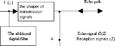
Let’s consider the cascade connection of a sending device and an echo-path to be the digital filter forming (Z).
The additional digital filter included in parallel to a sending device forms signals S ( Z ).
Equality (2) does not impose restrictions on a signal of transmission V ( Z ) and allows to transmit it without a protective time interval.
In its turn equality (2) falls apart into the following equalities [3]:
Ц ( z ) = П._1( z ) • -S^ Si_ i ( z )
Ц ( z ) = П._2( z ).
S ( z ) S _ i ( z ) — S i _ 1 ( z ) S i _ 2 ( z )
П . ( z ) = 2П . ( z ) + 2Й . ( z )
Equality (3) is a basis for the synthesis of the invariant echo-jack of the second order. The estimations of echo-signals on the previous blocks of processing can be used for calculation of the size of an echo-signal on the current block of processing. In fig. 1 the structure of the invariant echo-jack of the second order with control elements is presented.
In figure 1 it is clearly seen, that unlike the classical echojack, the invariant one is included before the intake. The invariant echo-jack is controlled by the transmission signals S ( z ). It results in the fact that its technical characteristics do not depend on correlations of signals of two directions. For echosignals an invariant echo-jack is an original rejector, and for reception signals it is a two-port network bringing minimum AHI and FHI. The characteristic of the invariant echo-jack is defined on the basis of laws of digital filtration [4].
1 _ - M 1 ( z ). z -1 _ - M 2 ( z ). z -2
H ( z ) = 2 , (4)
1 _ -M 1 ( z ). z _ _ -M 2 ( z ). z -2C
S ( z )
where M , ( z ) =------ is the 1st operating factor;
S _i ( z )
M, (z) = S(z) • S_1 (z) is the 2nd operating factor; S (z) -2V ’ S_1( z) S_2(z) P 6 ’ z is the image of a transmission signal on -block of processing; C < 1 – is an additional attenuator, included in a recursive chain.
For stable work of the offered structure it is necessary for the poles of the transmission characteristic to be inside the individual circle, then
M 1 ( z ) < 1, |
M 2( z ) < 1-J
When the chosen word length is equal to m , the maximum values 1( z ) 2( z ) are 2 m . If the operating factors have such values then the work of the invariant echo-jack will be unstable.
One of possible ways to solve the problem of stable work of the invariant echo-jack is the rationing of operating signals and echo-signals, together with reception signals.
The shaper of control signals
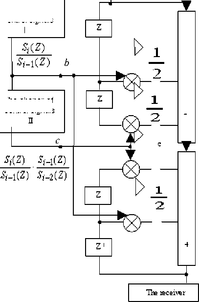
Fig. 1. The structure of the invariant echo-jack of the second order
The shaper of control signals
It will lead to the use of additional scaling two-port networks which should be included not only before an input of the invariant echo-jack itself (point a), but also on the inputs of the shapers of operating signals (points b and c) .
The other way to provide the stability of the invariant echo-jack of the second order is the transformation of a recursive part into a non recursive digital filter. From the theory of digital filtration it is known, that any recursive digital filter (CF) can be transformed into a non recursive digital filter [4].
Then
k
—--------------------------= 1 + £ Q ( Z ) ■ Z-i , (6)
1 - 2 m , ( z ) ■ z -1 - 2 m 2 ( z ) ■ c ■ z -2 -1
where k is the quantity of taps.
For the first five taps of the transformed structure the values Qi ( Z ) areaccordinglyequalto
Q ( Z ) = 2 M , ( Z );
1 , 1
Q 2 ( Z ) = 4 M ,2 ( Z ) + 2 M 2 ( Z ) ■ C ;
Q 3 ( Z ) =1 M , ( Z ) ■ M 2 ( Z ) ■ C +1 M , ( Z );
Q 4 ( Z ) = 1 M 22 ( Z ) ■ C 2 + 3 M 2 ( Z ) ■ M 2 ( Z ) ■ C + -3 M ,3 ( Z );
4 816
Q5 ( z ) = 3 M, (Z) ■ M 2 (Z) ■ C2 +1M 2 (Z) ■ M,2 (Z) ■ C+ 816
+-3 M ,3 ( Z ) ■ M 2 ( Z ) ■ c +2- M ,4 ( Z ).
In figure 2 the structure of the invariant echo-jack consisting of two in cascade joined digital filters is presented. In the first digital filter the indemnification of echo-signals is made. In the second digital filter the restoration of reception signals is made. It should be noted that the phase-frequency characteristic of two in cascade joined digital filters will be linear [4].
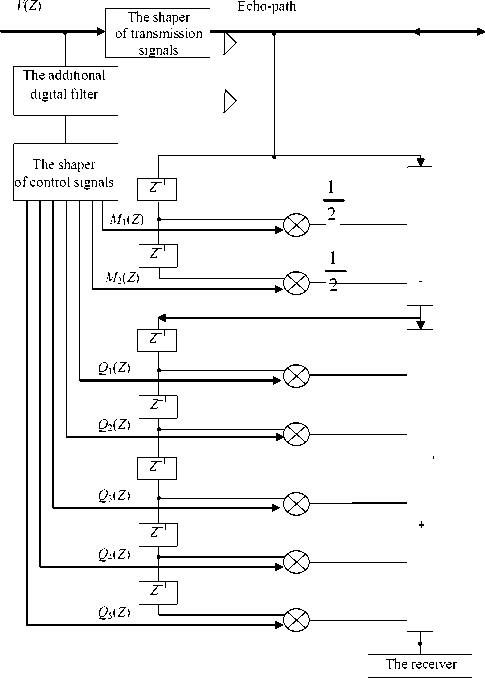
Fig. 2. The transformed structure of the invariant echo-jack of the second order
For the definition of technical characteristics of the developed invariant echo-jack we assume M1(z) = M2(z) = 1. Then the transmission characteristic will be equal to
H ( z ) =
1 — z
^^^^^^»
1 -2
z
1 -1 z-1
^^^^^^B
1 z -2C
Let’s decompose H ( z ) into two transmission functions of the first order
2 <7 2 (5 + 4 C + 71 + 8 C ) 2 °ow"“ 2 • (6 + 5 C ) 2
.
H ( z ) = H o( z ). H ,( z )=
1 + - z
1 - B 0 z -
1 - z -1
1 - B 1 z "' ’
The noise level of undercompensation in the invariant
echo-jack will be equal to
Bo =1 - 171 + 8 C , 044
to
° ™<1=о2 .z h 2( nT )
n = 0
B. =1 + 171 + 8 C ,
where h ( nT ) – is pulse reaction of the invariant echo-jack of the second order; a2cc - capacity of noise of a communication channel. At
where B 0and B 1arethepolesoftransmissionfunction.
Pulse reaction CFVH-2 is defined by convolution
h 0( nT ) h 1( nT ) .
The general level of self-noise CFVH-2 is defined by a known parity [4]:
Л N -1 д2 M N -1
a2 .Z h ( nT ) + K^S h , 2( nT ), (9)
12 n =0 12 , =1 n =0
where 7 - is a step of a quantum entrance word; 7 0 is a step of quantum in CFVH-2; h ( nT )–ispulsereactionCFVH-2; hj ( nT ) – is pulse reaction from j -th source of noise in CFVH-2 to an exit.
M , ( Z) = M 2( Z ) = 1 size Z h 2 ( nT ) * 1.003.
n =0
The overall performance of any method of signal processing can be compared with an overall performance of known methods. As an analogue we will use the characteristics of Widrow classical algorithm which is realized in the equipment of xDSL. Comparison will be made taking into account the level of self-noise and the value of
Let’s find the value of separate components included in equality (9), using Cauchy–Bunyakowsky inequality
N - 1 N - 1
Z h 2( nT ) = Z [ h o ( nT ) * h , ( nT ) ] < n = 0 n = 0
N - 1 Г N - 1
< Z Z h o ( nT )
n = 0 _ n = 0
N - 1 2
• Z h 1 ( nT ) ,
where symbol * designates the convolution operation.
If we omit intermediate calculations, the definitive result will be the following:
N - 1
Z h 2( nT ) = n = 0
( B 0 + 2)( B N - 2 -1)
( B 02 -1)
( B ^7 B rz1)
. ( B 12 -1) .
For the simplicity of computations in the process of calculation of the second composed expression (9) we will suppose that all pulse reactions from j -th source of noise to an exit are equal among themselves and are defined by value h ( nT ). Then the second composed expression (9) will be equal to (taking into account Cauchy–Bunyakowsky inequality)
undercompensation of an echo-signal.
In Widrow algorithm the adaptive filter joins in parallel with a sending device and models the parameters of an unknown system, i. e. of an echo-path. Pulse reaction of the adaptive filter depends on the connected channel (line) and can be arbitrary. For the simplicity of computations we will suppose that the pulse reaction of the adaptive filter is described by the readings of the homogeneous digital filter and is equal hA f( nT) = {1; c; c2; K... cn}, (15)
where c is the factor of transmission of the second tap of the adaptive filter ( F); c < 1.
For the calculation of self-noise level of the adaptive filter we will use expression (9). We will consider, that the word length of an entrance word 7 0 and the word length of processing 7 in the adaptive filter are equal. Besides we will suppose, that pulse reactions h ( nT ) from -th source of noise in the adaptive filter are equal among themselves and are defined by pulse reaction of all adaptive filter h F ( nT ). Omitting intermediate transformations, we definitively receive analytical expression of the calculation of self-noise level in Widrow classical algorithm:
22 n
П AF own = ( N + 1) .T- ^cy , (16)
12 1 — c
where N – is the quantity of taps of the adaptive filter;
n = {0; 1; ^»} - is a supervision step; c - is a factor of
M N -1 2 N -1
ZZ h , ( nT )] = 5 Z h 2 ( nT ).
j =1 n =0 n =0
transmission of the second tap of the adaptive filter; 7 - is a quantization step; 7= 2 m , m - is the word length of
If 7 = 70 then expression (9) becomes simpler and it will be equal to
a
7 2 ( B 0 + 2)( B 0 N - 2 - 1)
"2 ( B 02 - 1)
x
x
( B 1 - 1)( B 1 N - 2 - 1)
( B 12 - 1) .
Substituting the values of poles B 0 and 1 into equation
(12) we will definitively receive (at N > 1000)
processing.
Let’s estimate the noise level of undercompensation in Widrow classical algorithm which is caused by the influence of noise of a communication channel. The noise level of
undercompensation at an exit of the adaptive filter in classical algorithm is equal to [5]
F undercomp
y. N • R
12-y. N ’
where у - is a fine tuning step (in relative sizes), ye {0; 1};
N – is the quantity of taps in the adaptive filter; to to
R = Z h 7( nT ) + a 2c ; Z h 2F ( nT )–considersnoiseof n = N +1 n = N +1
work of the adaptive filter because of truncation of its pulse reaction to size N ; c 2 – is the capacity of noise of a communication channel.
At an intake input (a subtracter exit) in classical algorithm the level of noise of a communication channel doubles. It is caused by the fact that undercompensation noise σ2
AF undercomp and communication channel noise σ2 are not correlated.
The gain value in relative sizes will be equal to
Δ A =10lg⋅σ2 , σ
where σ2 – defines either the self-noise level or noise level of undercompensation in the invariant echo-jack; σ2 – defines either the self-noise level or noise level of undercompensation in Widrow algorithm.
For =0.9; N =100; n =1,000; m =12thesizeofΔ A ownwill be equal to 21.79db.
Similarly, for =0.9; N =100; γ=0.05; .c = 40db; the size Δ A undercomp will be equal to 5.3 db.
The received gain can be explained by several reasons:
Firstly, the invariant echo-jack is controlled by a transmission signal. The classical echo-jack is controlled by a signal of an error from a subtracter exit.
Secondly, the invariant echo-jack uses the readings of hindrance taken directly from a communication channel. The classical echo-jack calculates the echo-signal estimation artificially.
Thirdly, the work of the invariant echo-jack does not depend on correlation communications of signals of two directions.
The structure of the invariant echo-jack of the second order is synthesized. The overall performance of the invariant echo-jack is proved. The invariant echo-jack of the second order can find application in systems of telecommunications and objects control.
