Automated stand for electrical testing and diagnostics of life characteristics of lithium-ion batteries

Author: Kopylov E.A., Lobanov D.K., Mizrakh E.A.
Journal: Siberian Aerospace Journal @vestnik-sibsau-en
Section: Aviation and spacecraft engineering
Article in issue: 1 vol.23, 2022.
Free access
Lithium-ion batteries (LIB) are widely used as energy accumulators in the electrical power systems (EPS) of spacecraft. The article considers the automated bench SIA 12/24 for electrical tests and diagnostics of the resource characteristics of lithium-ion cells (LIC), on the basis of which the EPS LIB of spacecraft is developed and manufactured. LIC resource tests are the most time-consuming and lengthy, they are carried out in ground conditions for several months with repeated cycling of charge/discharge and cell temperatures until the conditions for completion of the tests are reached with periodic monitoring, measurement and registration of LIC parameters. The use of the automated bench, which makes it possible to carry out resource testing of LIC based on dynamic stress testing (DST), makes it possible to shorten the resource testing of LIC and thereby significantly accelerate the design and development of EPS LIB of spacecraft. The structure, the description of the component parts and the technical characteristics of the bench SIA 12/24 allowing to perform electrical tests simultaneously of twelve LIC are given. The principle of operation and technical characteristics of the original charging-discharge device with a load converter (CDD-LC) forming the basis of the bench are considered. The proposed original CDD-LC and load converter (LC) topologies with two-stage power conversion and stabilized bridge transformer converter (BTC) input voltage make it possible to automate the process of lithium-ion cells electric testing by automatically reproducing functionally necessary test modes and by ensuring energy saving in cells charging-discharge modes. For a two-stage power conversion CDD-LC, it is shown that the use of BTC input voltage stabilization gives the following benefits: – extension of the LIC attribute control ranges: current, voltage, power; – low dependency of static error of stabilization of LIC attributes and transition quality indicators on the type of LC load.
Bench, lithium-ion cell, tests, resource characteristics, charger-discharge device, load converter
Short address: https://sciup.org/148329611
IDR: 148329611 | UDC: 621.316.721 | DOI: 10.31772/2712-8970-2022-23-1-93-104
Text of the scientific article Automated stand for electrical testing and diagnostics of life characteristics of lithium-ion batteries
Lithium-ion rechargeable batteries (LIB) are widely used as electric power storage devices for modern eletrical power supply systems (EPS) of spacecraft [1–3] to ensure the power consumption of the spacecraft in the "shadow" parts of the orbit and in the modes of maximum power consumption (spacecraft position correction, payload consumption, radio transmitting and other systems). The LIB resource practically determines the period of the spacecraft active existence.
In order to ensure the required parameters and quality of LIB, manufacturers perform electrical tests of several batteries (LIB) simultaneously [4–5].
The technological process of LIB electrical testing includes:
– determination of the nominal values of capacity, power and energy;
– charge storage tests;
– energy efficiency tests;
– life tests to confirm the LIB cyclic life.
Based on the types of electrical tests listed above, LIB life tests are the most labor-intensive and lengthy, they are carried out on the ground for several months with repeated cyclic reproduction of charge / discharge modes and battery temperatures until the test completion conditions are reached with periodic monitoring, measurement and registration of LIB parameters. Reducing the life test period for LIBs makes it possible to significantly speed up and reduce the cost of designing and testing LIBs and EPSs of a spacecraft. For this purpose, standards have been developed [6–8] in which LIB life tests are based on the dynamic stress testing (DST) technique, which uses charge/discharge modes with increased values of direct currents and power up to the maximum values set by the manufacturer.
In the special literature, the issues of designing the LIB charging-discharging units, which have relatively high nominal voltages (40–100V) [9–12], are mainly covered. However, the issues of development and design of the charge-discharge devices (CDD) for individual LIB with a relatively low voltage are practically not considered (less than 4.5 V).
Thus, there is a contradiction between the modern requirements for the methods and modes of technological processes for LIB electrical testing and the insufficient development of hardware for LIB testing processes.
Objective
Based on the modern requirements for the technological processes of LIB electrical testing, we propose the design concept and main characteristics of a promising stand that allows electrical testing of large-capacity LIBs for spacecraft, including accelerated durability tests.
Materials and methods for solving the problem
The bench for durability tests of lithium-ion batteries (SIA 12/24) is designed to solve the following tasks:
– reproduction of electrical and temporary modes of the battery operation both in the mode of a given power and in the mode of a given current;
– measurement and registration of electrical, temperature and time parameters of the battery operation modes;
– ensuring the management of the battery electrical and thermal tests in accordance with the specified cyclograms;
– provision of automatic diagnostics of the stand serviceability and protection of the battery from emergency modes.
Structural diagram of the bench SIA 12/24
The block diagram of SIA 12/24 is shown on fig. 1. SIA 12/24 includes functionally necessary blocks:
– block of protective circuit breaker;
– three uninterruptible power supplies (UPS) – EATON 9130;
– bench load block (BNS-30);
– twelve galvanically independent charging-discharging devices (CDD 160-5);
– twelve stabilizing power supplies – LAMBDA GEN 8-180;
– control measuring computer complex– NI PXIe-1082;
– thermal chamber with batteries under study (TC);
– interface device (ID).
The block of circuit breakers is designed to connect (disconnect) the SIA 12/24 UPS to an industrial three-phase network ~ 380/220 V ± 10% with a frequency of (50 ± 1) Hz. Uninterruptible power supplies provide uninterrupted power supply to the complex in the event of an emergency power outage.
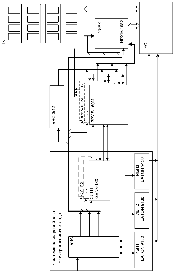
Рис. 1. Структурная схема стенда СИА 12/24
Fig. 1. Structural diagram of the bench SIA 12/24
Each of the twelve CDD 160-5 charging and discharging units is connected to the borons of the corresponding battery and regulates the charge and discharge current of the battery in accordance with the cyclogram set with control measuring computer complex. To utilize excess electricity each switchgear is connected to a corresponding load located in the load block of the BNS-30 bench.
Also, in the load block of the BNS-30 bench, there is a power distribution device from the EATON 9130 UPS between the control measuring computer complex, twelve CDDs 160-5, and twelve SIPs LAMBDA GEN 8-180 connected to them.
Temperature tests are carried out in a heat chamber controlled via the control measuring computer complex. The thermal chamber control provides the following functions:
-
– measurement and registration of battery temperature sensors’ readings in a heat chamber;
– temperature control equipment management;
– signaling and disconnecting the battery power line when the battery temperature goes beyond the allowed limit.
Control measuring computer complex registers the attributes of the battery testing process (currents, powers, voltages and temperatures of batteries) and allows to:
-
– set battery test modes by programming CDD;
-
– set the values of hardware and software protections;
-
– monitor the operation of the UPS;
-
– signal and display emergencies.
Technical characteristics of the bench SIA 12/24
Battery voltage range from -5 to +5 V (resolution 0.05 V).
The range of charge current change in the battery is from 1 A to 80 A (resolution 0.1 A).
Range of discharge current change in the range from 1 A to 160 A (discreteness 1 A).
The range of time intervals change is from 1 s to several hours in increments of no more than 1 s, the interval reproduction accuracy should be within ±0.1 s.
Battery temperature range from -10 to +60 °С.
The accuracy of parameter registration is presented in the table.
Charge and discharge currents registration error
|
Range, А |
Error, mА |
|
0–5 |
± 30 |
|
5–50 |
± 50 |
|
50–160 |
± 200 |
Accumulator voltage registration error is no more than ±5mV.
Time interval registration error is within ± 0.1 s
Accumulator temperature registration error is no more than ±2 °C.
The number of simultaneously tested batteries: from one to twelve. All batteries are galvanically isolated from each other.
The bench allows parallel operation of two modules, while the combined modules provide a charge current of up to 160 A, a discharge current of up to 320 A.
Bench dimensions WxHxD, mm: 560x910x820.
Weight, kg: 200±5.
The LIB test benches are based on charge-discharge devices.
Currently, charging and discharging unit CDD is widely used with a load converter containing [11– 12] a grid-driven inverter that provides the recovery of excess electricity to the industrial AC voltage network.
The general disadvantages of such CDD-LC during LIB testing are:
-
– limiting the maximum value of the LIB current at low voltage levels of the LIB, due to the presence of the final resistance of the switches and the active resistance of the inductor;
-
– inability to discharge batteries with direct current until the voltage polarity changes (polarity reversal);
-
– impossibility of regular testing and shutdown of the LIB test complex (bench) in case of an emergency shutdown of the AC network.
These shortcomings do not allow to study and test high-capacity LIBs in all required modes.
Structural diagram of the CDD 160-5
Therefore, the authors developed a new structure of the charging-discharging device - CDD 160-5 [13; 15; 16]. In the proposed scheme (Fig. 2), the charger and switchgear are combined into one device containing an uninterruptible power supply, an adjustable stabilizing power supply (SPS), a three-position switch, and an original controlled load converter (LC) of the regenerative type [14]. Battery (A) connected in series with a battery current sensor, is included in the diagonal of the switch, formed by a bridge circuit of semiconductor switches K 1 - K 4 . LC in the current stabilization mode stabilizes and regulates the charge / discharge currents in the required range. In the power stabilization mode and the charge mode with LIB voltage stability, the current value is calculated taking into account the measured LIB voltage.
The adjustable SIP stabilizes the voltage drop across the LC, which makes it possible to limit the power of the LC, to ensure the discharge of the LIB with a high current, the discharge to zero voltage (with compensation for the voltage drop across the active resistances of the current-carrying circuits) and to negative values of the LIB voltage. The stabilization voltage is selected from the condition of providing the required wide range of battery current regulation (A).
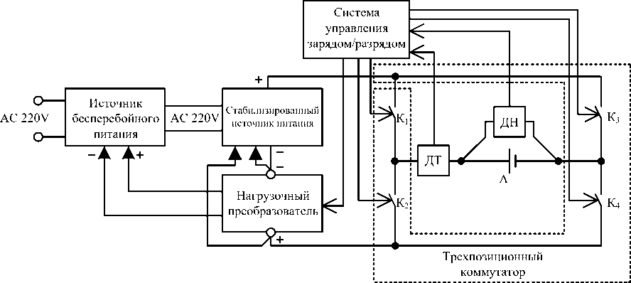
Рис. 2. Структурная схема ЗРУ 160-5:
А – аккумулятор; ДТ – датчик тока; ДН – датчик напряжения
Fig. 2. Structural diagram of the CDD 160-5
А – battery; ДТ – current sensor; ДН – voltage sensor
In the proposed CDD (Fig. 2), the regulation and stabilization of the current in the charge (Fig. 3) and discharge (Fig. 4) modes is performed by the LC in accordance with the LIB electrical test program during cyclic reproduction of the charge-discharge profiles.
LC Specifications
-
1. Range of current change from 0.1 to 160 A (resolution 0.1 A) at a constant input voltage LC.
-
2. The range of time intervals is from 1 s to several hours in increments of no more than 1 s.
-
3. The maximum rate of current change is 60 A/s.
-
4. Stabilization and attribute setting errors:
-
a) ±1% for current;
-
b) ±0.1% for time;
-
c) ±1.1% for power.
To ensure the required charge/discharge profile, the LIB LC contains an input current stabilizer, consisting of a control system, an impulse boost converter (IBC) and an IBC input current sensor.
The choice of the IBC as the first stage of the LIB charge/discharge current stabilizer is due to a significant decrease (especially at high values of the converted currents) of the battery current ripples caused by the use of the functional required input inductor of the IBC.
The device can operate in the mode of charging, discharging and interrupting the current (pause) of the battery. These modes are provided using a three-position switch, implemented on the battery keys K 1 - K 4.
To operate the device in the battery charging mode, the control system (CS) closes the electronic keys K 1 and K 4 . In this mode, the LIB is charged along the circuit: the positive terminal of the SIP, the first electronic key K 1 , current sensor, then the electronic key K 4 , LC, and the negative terminal of the SIP (Fig. 3). The charge/discharge control system regulates the charging current of the regenerative type LC depending on the voltage value of the current sensor and voltage sensor of the LIB. LC returns (recovers) excess electricity to the DC power supply of the UPS, from which the SIP is powered.
To operate the device in the battery discharge mode, the charge / discharge control system closes the electronic switches K 2 and K 3 . In this mode, the battery is discharged (Fig. 4) along the circuit: current sensor, electronic key K 2 , LC, negative output of the SIP, then positive output of the SIP and electronic key K 3 . In this mode, the LC also recovers excess electricity to the DC power supply of the UPS.
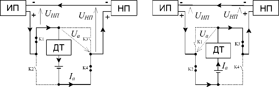
Рис. 3. Схема ЗРУ в режиме заряда аккумулятора
Fig. 3. CDD circuit in cell charge mode
Рис. 4. Схема ЗРУ в режиме разряда аккумулятора
Fig. 4. CDD circuit in cell discharge mode
LC power for the maximum current I a max LIB proportional to voltage U LC :
max
' НИ I a U НП.
To limit the LC power, the voltage U LC is stabilized by the SIP. The analysis showed that the minimum voltage U LC should be practically equal to the maximum voltage of the LIB, i.e. U LC ≈ 4.0 V.
The voltage U SIP depends on the LIB operating mode, thus when charging
U НП = U СИП U a ;
When charging
U НП = U СИП + U a .
Based on (1) it followsthat maximum voltage USIPmax of the SIP sourse is to be chosen on the condition that max max
U СИП - U НП + U a
.
Thus, SIP should provide the maximum current I a max = 160 А, maximum voltage U SIP max . As a SIP, the authors chose a stabilizing voltage source - LAMBDA GEN 8–180, which fully meets the listed requirements.
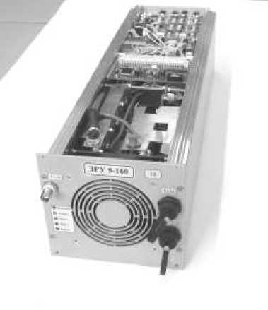
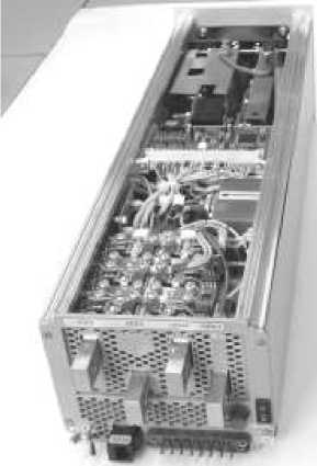
The appearance of the developed CDD 160-5 is shown in fig. 5.
а
Рис. 5. Внешний вид ЗРУ-НП без верхней крышки: а – со стороны фронтальной панели; б – со стороны задней панели
б
Fig. 5. Appearance of the CDD-LC without the top cover: a – from the front panel; b – from the back panel
Bench SIA 12/24
For the simultaneous study of the electrical characteristics of twelve LIBs, on the basis of the developed CDD 160-5, the authors manufactured and put into operation the bench (Fig. 6) SIA 12/24 SGAU. 565211.023 including:
-
- CDD1-14 charging-discharging device;
– control measuring complex National Instruments
– programmable power supply GEN8-180;
-
- load block BN-27;
– test load NT-5-160;
– interface device ID.
The control measurement complex is based on standard National Instruments (NI) PXI system modules, which ensures the reliability, accuracy, flexibility and scalability of the control system.
The CS was implemented using the NI PXI platform with the NI PXI-8115 controller, NI PXIe-4300 isolated analog input modules (3 pcs.), NI PXI-6225 analog input modules (1 pc.), and the RS485 interface on the modules. NI PXI-8433/2 (1 pc.).
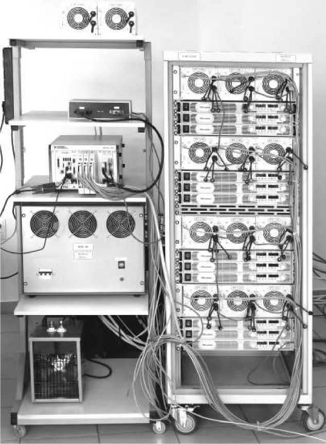
Рис. 6. Внешний вид стенда СИА12/24
Fig. 6. Appearance of the bench SIA12/24
The studied LIBs are not galvanically connected to each other, therefore, the signals from the voltage and current sensors of the battery are fed to the module of isolated analog inputs NI PXIe-4300. The NI PXI-6225 analog input module is used to collect information from TMP36FT9 temperature sensors. To measure the battery current, a high-precision LEM current sensor is used, the signal from which is fed to the input of the PXIe-4300 module.
Conclusion
-
1. The analysis of possible CDD topologies has shown that the combination of regulators-stabilizers of the charging and discharging units in one device - a load converter (LC) makes it possible to reduce the weight, dimensions and improve the operational properties of the CDD LC.
-
2. The proposed original topologies of CDD-LC (utility model patent No. 123530) and load converter (utility model patent No. 153595) with two-stage power conversion and input voltage stabilization of the bridge transformer converter (BTC) make it possible to automate the process of
-
3. For CDD-LC with two-stage power conversion, it is shown that the use of BTC input voltage stabilization makes it possible to impart the following positive properties to LC:
lithium-ion batteries electrical testing by automatically reproducing functionally necessary test modes and ensure energy saving in charge-discharge modes of batteries.
-
– expansion of control ranges for LIB attributes: current, voltage, power;
-
– weak dependence of the static stability error of the LIB attributes and quality indicators of transient processes on the type of LC load.
These properties simplify the choice of CDD-LC parameters that provide the required stability error of the LIB attributes.
References Automated stand for electrical testing and diagnostics of life characteristics of lithium-ion batteries
- Gruzdev A. I. [Conceptual approaches to the development of batteries with increased specific energy intensity for aerospace applications]. Matters of Electromechanics. VNIIEM Proceedings. 2015, Vol. 147, P. 38–43 (In Russ.).
- VcKissock B. I. et al. Progress of ongoing NASA Lithium-Ion cell Verification testing for aerospace applications. NASA/TM-2008-215154. 2008.
- Pearson C., Thwaite C., Russel N. Small Cell Lithium-Ion Batteries: The Responsive Solution for Space Energy Storage. Paper AIAA RS3-2005-5003 presented at the 3rd Responsive Space Conference. Los Angeles, CA, USA, April, 2005, P. 25–28.
- Borthomieu Y., Broussely Y., Planchat J. P. VES140 S Li-Ion Cell GEO Life Test Results. SAFT, SIXTH EUROPEAN SPACE POWER CONFERENCE (ESPC). Porto, Portugal, 6–10 May 2002.
- Popov V. A., Kulyga V. P., Lihonosov S. D., Mahotkin D. N. [Results of the analysis of degradation of LIA electrodes in life tests]. Fundamentalnye problemy preobrazovaniya energii v litievyh elektrohimicheskih sistemah. Matireals of the XXII International Conference. Krasnodar, 2012, P. 26–27 (In Russ.).
- GOST R MEK 61427-1-2014. Akkumulyatory i akkumulyatornye batarei dlya vozobnovlyaemyh istochnikov energii. Obshchie trebovaniya i metody ispytanij. Chast 1. Primenenie v avtonomnyh fotoelektricheskih sistemah [State Standard R MEK 61427-1-2014: Accumulator cells and batteries for renewable energy sources. General requirements and test methods. Part 1. Applications in autonomous photovoltaic systems]. Moscow, Standartinform Publ., 2014, 13 p.
- GOST R MEK 61960-2007. Akkumulyatory i akkumulyatornye batarei, soderzhashchie shchelochnoj i drugie ne kislotnye akkumulyatory. Akkumulyatory i akkumulyatornye batarei litievye dlya portativnogo primeneniya [Accumulator cells and batteries containing alkaline and other non-acid batteries. Accumulator cells and batteries for portable use]. Moscow, Standartinform Publ., 2007, 9 p.
- GOST R MEK 62660-1-2014. Akkumulyatory litij-ionnye dlya elektricheskih dorozhnyh transportnyh sredstv. Chast 1. Opredelenie rabochih harakteristik [Lithium ion accumulators for electric road vehicles. Part 1. Determination of operating characteristics]. Moscow, Standartinform Publ., 2015, 29 p.
- Pochebut D. V. et al. [Method for carrying out life tests of space-purpose accumulators and device for carrying out said method]. Patent RF, no. № 2009108898/11, 2009.
- Vellucci F. et al. Life cycles test on a lithium battery system. IECON 2014 – 40th Annual Conference of the IEEE Industrial Electronics Society. 2014. P. 3129–3134.
- Bubnov O. V., Kremzukov Yu. A., Pchelnikov V. A., Rulevskij V. M., Shurygin Yu. A. [Automated workstation for the development and testing of energy conversion equipment of the spacecraft electrical power supply system]. Proceedings of TUSUR University. 2017, Vol. 20, No. 3, P. 35–39 (In Russ.).
- Noskin G. V., Zernov A. S., Mishin V. N., Pchelnikov V. A., Smolencev A. A., Filin V. M. [Unified station for charge and testing of space and ground-based lithium-ion battery systems]. News from the Russian Academy of Sciences. Energy. 2012, No. 2, P. 120–125 (In Russ.).
- Mizrakh E. A. et al. [Accumulator cell test device]. Patent RF, no. 2012127508, 2014.
- Mizrakh E. A. et al. [Voltage converter]. Patent RF, no. 2014147920, 2014.
- Fedchenko A. S. et al. Study of a lithium-ion battery charge-discharge test unit characteristics. IOP Conf. Series: Materials Science and Engineering. 2016, No. 122, P. 012015. Doi: 10.1088 /1757-899X/122/ 1/012015.
- Mizrah E. A. et al. On the Static Accuracy of Charge-Discharge Units Intended for Electrical Tests of High Capacity Li-ion Batteries. IOP Conference Series: Materials Science and Engineering, International Siberian Conference Reshetnev Readings-2016. 2016. Doi:10/1088/1757-899X/255/1/012016.
