Automatic Joint Guidance and Beam Focusing Device for electron-beam welding

Author: Braverman V.Ya., Bogdanov V.V., Platonov O.A.
Journal: Siberian Aerospace Journal @vestnik-sibsau-en
Section: Technological processes and material science
Article in issue: 3 vol.22, 2021.
Free access
Physical, technological and power characteristics of the Electron Beam Welding (EBW) support its application in those circumstances that require greater focus on features and quality of the welding joints and improved weight and robustness aspects for individual joints of an object and products as a whole. At the same time, those characteristics of the EBW establish it as a complicated process that results from multiple factors interacting with one another. The quality of a welding joint depends on the precision of the beam alignment with the joint plane and the positioning of the minimum section (focus) of the electron beam in the penetration channel. These factors have a significant impact on the welding depth, the shape of the seam and presence of defects in it. The challenge of providing precise positioning of the beam along the joint of the welded parts is especially critical during the welding of long joints of large construction parts. This level of precision requires reliance on equipment for automatic beam alignment with the seam. Dispersion and re-reflection of the electrons in the beam leads to the loss of focus for the beam at a stable current of the focusing system. To obtain the data for the beam’s position at the seam and the position of the beam’s focus at the welding surface, we use phenomena closely associated with the EBW, such as the secondary electron emission and the X-ray radiation in the welding area. We are presenting a functional diagram of a device for the automatic positioning and focusing of the electron beam.
Electron beam welding, secondary electron emission, X-rays, the deflection of the beam from the joint, defocusing, the frequency selection of the sensor’s signal
Short address: https://sciup.org/148329584
IDR: 148329584 | DOI: 10.31772/2712-8970-2021-22-3-517-525
Text of the scientific article Automatic Joint Guidance and Beam Focusing Device for electron-beam welding
Intoduction
Physical, technological and power characteristics of the Electron Beam Welding (EBW) support its application in those circumstances that require greater focus on features and quality of the welding joints and improved weight and robustness aspects for individual joints of an object and products as a whole. In particular, EBW is widely used for obtaining permanent joints in the aggregate and body production of aerospace products (Fig. 1). The complexity and multifactoriality of the EBW process leads to the problem of weld quality reproducibility and the need for process control. The challenge of providing precise positioning of the beam along the joint of the welded parts is especially critical during the welding of long joints of large construction parts. The permissible error of alignment of the beam with the joint usually does not exceed 0.2 mm. Such accuracy necessitates the use of automatic beam guidance devices.
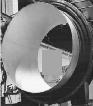
Рис. 1. Пример оболочковой конструкции крупногабаритного изделия
Fig. 1. An example of a shell structure for a large-sized product
Dispersion and reflection of electrons in the beam leads to defocusing of the beam at a stable current of the focusing system. In this case, the penetration depth becomes unstable, which negatively affects the quality of the joint, especially in the final stages of assembly. This situation necessitates stabilizing the position of the beam focus relative to the surface of the parts to be welded.
As a source of information about the position of the beam relative to the joint and the position of the beam focus relative to the surface of the parts to be welded, one can use the braking X-ray radiation and the secondary electron emission accompanying the EBW process [1–8].
Formalization of the problem
The relations determining the dependences of secondary-emission current I (ε) and intensity J (ε) of X-ray radiation on the position ε of the beam relative to the joint during EBW are known [9].
I вэ ( £ ) = K вэ Ф ( x ) IF ; J ( s ) = KpCZU 2 IF ,
where I is the beam current; I вэ (ε) is the secondary-emission current; J (ε) is the X-ray intensity; φ is the secondary emission coefficient; K вэ is the coefficient taking into account the share of secondary electrons coming to the sensor [9]; K р is the coefficient taking into account the share of X-ray radiation passed through the sensor crystal area [10]; C is the proportionality factor; U is the accelerating voltage; Z is the atomic number of the target (for parts to be welded); ε is the mathematical expectation (position of the beam relative to the joint of the parts to be welded); F is the beam current distribution function
A
F = 1 -
σ2 π
( x - E )
J e '
2σ
J dx
A
where σ is the standard deviation of the electrons from the beam axis; Δ is the gap in the joint.
The analysis of expressions (1) and (2) shows that the dependences I вэ (ε) and J (ε) are identical and are determined by the distribution function. The minimum of these dependences appears at ε = 0, i.e. at coincidence of beam and joint coordinates (Fig. 2) [11; 12].
Extreme character of I вэ (ε) and J (ε) dependences testifies to possibility of determination of the ray position relative to the joint by the known ways of extremum search: [13]. These methods can be reduced to the following integral operation
T
I = J G ( t ) ф ( t ) dt , (3)
where G(t) = f(t) + η (t) is the sum of the signal and interference respectively; φ (t) is the weight function determining the reception mode; T is the period.
Thus, for example, we have:
– accumulation method – φ( t ) = 1;
– autocorrelation method – φ( t ) = G( t – τ);
– coherent method – φ( t ) = f( t );
– filtering – φ( t ) = g ( T – t ), where g ( t ) is the impulse function of the filter.
The methods described by formula (3) give results close to the limit signal/interference ratio [13]. This means that the question of choosing a method of reception moves into the area of technical and technical-economic conditions.
In the process of EBW due to scattering and reflection of electrons in the penetration channel, the beam can be defocused (σ increases). This leads to a change in the beam power density and, consequently, to a deviation of the weld parameters from the required values.
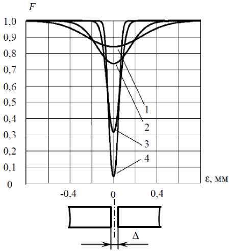
Рис. 2. Расчетные зависимости F от положения луча относительно стыка:
Δ = const = 0,1 мм, σ = var ; 1 – σ = 0,25 мм; 2 – σ = 0,15 мм; 3 – σ = 0,1 мм; 4 – σ = 0,05 мм
Fig. 2. Calculated dependences of F on the position of the beam relative to the joint:
Δ = const = 0,1 mm, σ = var ; 1 – σ = 0,25 mm; 2 – σ = 0,15 mm; 3 – σ = 0,1 mm; 4 – σ = 0,05 mm
The expression (2) and graphs (Fig. 2) show that increasing σ leads to a decrease in the dynamic range of change in the F -function of the beam current distribution. This phenomenon can be used to measure the degree of defocusing and to control the position of the beam focus with a focusing system.
In the EBW process, the current value of σ can be represented as follows [11]:
σ = σ0+ Δσ,(4)
where σ 0 is the minimum σ for a given electron-beam gun; Δσ is the increment σ caused by the features of the EBW process.
Hence, the algorithm for stabilizing σ at a level close to σ 0 is obvious:
σ0= σ – Δσ.(5)
During EBW, σ is controlled by the focusing system of the EBW. In this case the change of current Iф of the focusing system (FS) relative to current Iф0, corresponding to σ0, leads to increase of σ irrespective of a sign of increment ΔIф. In this case c = Co + |^(^ф )|,(6)
where Δσ(Δ I ф ) is the increment σ of the current increment Δ I ф . The dependence Δσ(Δ I ф ) can be represented as follows [14]
Ло ( Л 7 ф ) = R
( I ф0 + л ф )
I ф02
- 1
where R is the focusing system parameter (mm); I ф0 is the FS current corresponding to σ 0 .
Substituting (4), (7) into expression (2) allows us to determine the dependence of the distribution function F 0 on the change of I ф relative to I ф0 at zero displacement of the beam relative to the joint (ε = 0):
F 0
= 1 -
1^ 0
( I ф0 + A ф ) 2
2 I ф0
> dx.
Fig. 3 shows a graph built according to this formula. The calculation is made for electron-beam gun КЭП-2М ( R = 10 mm; I ф0 = 50 mA; σ 0 = 0,1 mm; the gap in the joint Δ = 0,1 mm).
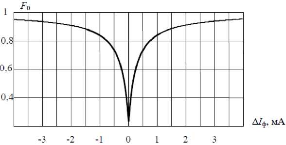
Рис. 3. Зависимость функции распределения F 0 от степени расфокусировки луча
Fig. 3. Dependence of the distribution function F 0 on the degree of defocusing of the beam
From the graph we can see that changing the focusing current relative to the current Iф0 leads to to decrease the range of variation of the distribution function. An increase in σ leads to the same effect.
Taking into account (6), (7), expression (5) will look like
^ 0
= CT-
( I ф0 + A I ф ) 2
2 I ф0
- 1
Thus, by measuring F (the current value of σ) and comparing it with F 0 (σ 0 ), it is possible to form a control signal Δ I ф to correct the size of the heating spot
A ф
( I фо + A I ф ) 2
- 1
2 I ф0
Functional scheme
The automatic joint tracking and focusing of the electron beam is implemented on the STM32F405RGT6 microcontroller according to the functional diagram shown in Fig. 4.
The control is performed via two channels: the beam position control channel relative to the joint and the σ stabilization channel by controlling the FS current.
The first channel (the faster one) provides the alignment of the beam with the joint during welding (maximum value of F). Using the STM32F405RGT6 microcontroller allows you to implement any of the above methods of receiving the sensor signal in accordance with (3) to determine the position of the beam relative to the joint. In this case, the choice of the reception method is made programmatically.
In the paper, the joint tracking channel is represented by an extreme regulator based on coherent sensor (Д) signal reception - secondary emission or X-ray signal [15]. The search signal generator (ГПС) scans the joint of the parts to be welded with an electron beam and generates a reference signal φ ( t ) for the synchronous detector СД. The sensor signal is converted by the synchronous detector into the voltage proportional to the beam deflection ε from the joint and through the amplifier (У) is fed into the deflecting system (ОС) of the electron-beam gun, eliminating the mismatch of the beam and the joint positions.
The beam focus position stabilization channel is represented by an extreme regulator based on sensitivity extremum search [16]. The signal from the sensor output through the rectifier (B) goes to the input of the comparison device (УС). At the rectifier output the analog of the current value F is formed. The focusing current source (ИФТ) sets the required value of current I ф0 in the focusing system (ФС). The current is injected until the maximum voltage value is obtained at the rectifier output. This voltage value (analogue of F 0 ) is stored in the setting device (ЗУ) and fed to the second input of УС.
The current control signal of ФС is generated by the search signal generator ФПС in case of inequality of values F and F 0 . If the condition F < F 0 is fulfilled, ФПС generates a signal Δ I ф . If the difference F – F 0 increases (in absolute value), ФПС changes the sign of Δ I ф . This decreases the value of Δ I ф . The process continues until the condition F = F 0 is fulfilled.
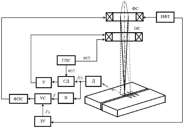
Рис. 4. Функциональная схема устройства автоматического слежения за стыком и фокусировки луча
Fig. 4. Functional diagram of the device for automatic tracking of the joint and focusing the beam
Conclusion
The device was tested under laboratory conditions at M.F. Reshetnev Siberian State University on the electron-beam unit ЭЛУ-8. Circular specimens with thickness of 20 mm and diameter of 500 mm were welded from materials АМГ-6 and Х18Н10Т.
Beam alignment error with the joint does not exceed 0.15 mm.
Stabilization of the heating spot position increases the reproducibility of geometrical parameters of welds and reduces the number of root defects.
References Automatic Joint Guidance and Beam Focusing Device for electron-beam welding
- Reichmann A., Leffler D., Bartel R. [State of the art of a FEP control unit of beam scanning for electron beam equipment]. 6th International Conference on Beam Technology. Halle (Saale), 2014, P. 102–107.
- Spynu G. A, Pastushenko Y. I. [Modern secondary emission systems for automatic direction of the electron beam along the joint during welding]. Avtomat. svarka. 1978, No. 10, P. 18– 8 (In Russ.).
- Braverman V. Ya., Belozertsev V. S. [Controlling the formation of a weld in electron beam welding]. Vestnik SibGAU. 2008, Vol. 19, No. 2, P. 148–152 (In Russ.).
- Braverman V. Ya., Bogdanov V. V., Oborin L. A. Analysis of the secondary emission current and X-ray radiation dependency on the beam’s position along the joint during electron beam welding. IOP Conference Series: Materials Science and Engineering. 2020, Vol. 822. Doi:10.1088/1757-899X/822/1/012032.
- Braverman V. Ya. [Analysis of the dependence of the secondary emission current and X-ray ra-diation on the position of the beam relative to the joint during electron beam welding]. Izvestiya Sa-marskogo nauchnogo tcentra RAN. 2016, Vol. 18, No. 2 (3), P. 853–857 (In Russ.).
- Braverman V. Ya. [Bremsstrahlung X-ray radiation in electron beam welding and its relation-ship with process parameters]. Vestnik SibGAU. 2008, Vol. 20, No. 3, P. 117–121 (In Russ.).
- Braverman V. Ya., Belozertsev V. S. [Experimental studies of the dependence of X-ray radiation on the position of the beam relative to the joint in electron beam welding]. Vestnik SibGAU. 2009, Vol. 22, No. 1, P. 100–103 (In Russ.).
- Braverman V. Ya., Belozertsev V. S. [Analysis of the dependence of X-ray radiation on the po-sition of the penetration channel relative to the joint during electron beam welding]. Vestnik SibGAU. 2010, Vol. 27, No. 1, P. 131–134 (In Russ.).
- Bronshteyn I. M., Frayman B. S. Vtorichnaya elektronnaya emissiya [Secondary electronic emission]. Moscow, Nauka Publ., 1969, 408 p.
- Kharadzha F. N. Obshchiy kurs rentgenotekhniki [General course of X-ray engineering]. Mos-cow, Energiya Publ., 1966, 568 p.
- Braverman V. Ya., Belozertsev V. S., Goryashin N. N. [Mathematical models of the processes of changing the X-ray radiation from the position of the beam relative to the joint during electron beam welding]. Vestnik SibGAU. 2009, Vol. 22, No. 2, P. 247–251 (In Russ.).
- Braverman V. Ya., Belozertsev V. S. [Dependence of X-ray radiation on the position of the beam relative to the joint at different degrees of focus in the process of electron beam welding]. Vest-nik SibGAU. 2010, Vol. 28, No. 2, P. 121–125 (In Russ.).
- Kharkevich A. A. Bor'ba s pomekhami [Anti-jamming]. Moscow, Nauka Publ., 1965, 384 p.
- Bashenko V. V. Elektronno-luchevye ustanovki [Electron beam installations]. Leningrad, Mashinostroenie Publ., 1975, 168 p.
- Braverman V. Ya., Bogdanov V. V. Tracking on the joint during the electron beam welding. IOP Conference Series: Materials Science and Engineering. 2016, Vol. 155. Doi:10.1088/1757-899X/155/1/012023.
- Bessekerskiy V. A., Popov E. P. Teoriya sistem avtomaticheskogo regulirovaniya [Theory of automatic control systems]. Moscow, Nauka Publ., 1966, 992 p.
