BER Based Performance Analysis of 2x1 Alamouti's Diversity and 4x4 MIMO Diversity with Interleaver and Encoder for BPSK, QPSK and QAM

Author: Jaya Dagur, Savita Sindhu
Journal: International Journal of Information Engineering and Electronic Business(IJIEEB) @ijieeb
Article in issue: 1 vol.9, 2017.
Free access
In this paper the results are evaluated on a conventional modulation system. Here the system of communication is presented by modeling and analysis and the results so calculated are presented. The approach made in this paper is solely based on initial description which includes a combinational approach of spatial diversity well represented by OSTBC (Orthogonal Space Time Block Codes) encoder and combiner. Next the system of OSTBC encoder and combiner are put together in a MIMO(Multiple Input Multiple Output) channel using Rayleigh and Rician channel coupled with white Gaussian channel. In modeling of such systems interleavers and encoders are also used that helps to identify the performance with simple model without these techniques. In overall system the methodical approach using Multiple Input Multiple Output antenna with the modulator, encoder and interleaver is analyzed and the resultant bit error rate has been identified. The simulation platform is MATLAB and SIMULINK in which communication block sets are used. Alamouti's and 4x4 MIMO antennas are used and hence performance so evaluated is delivered. Best results are found when number of antennas increases using Interleaver and modulation or only with modulation techniques.
4x4 MIMO, BER (Bit Error Rate), encoder, Interleaver, Alamouti's diversity, QAM, QPSK, BPSK
Short address: https://sciup.org/15013496
IDR: 15013496
Text of the scientific article BER Based Performance Analysis of 2x1 Alamouti's Diversity and 4x4 MIMO Diversity with Interleaver and Encoder for BPSK, QPSK and QAM
Published Online January 2017 in MECS
Multiple - Input Multiple - Output is a wireless technology having multiple transmitters and multiple receivers for transferring a huge amount of data stream at same time .MIMO Technology makes antennas to work smarter by combining the data receiving from different antennas at different times at the receiver side, it effectively increases the power of receiving signal .MIMO technology increases the capacity of the channel. By adding more receiving and transmitting antennas it linearly increases the total output of the channel. MIMO Technology uses the channel bandwidth more effectively. The future generation wireless communication systems will need to provide services of high data rate. In wireless communication time varying multipath fading makes the system non reliable. It is difficult to maintain the signal quality and reduce the effective error rate (BER).
Power control of transmitter is the most efficient technique to combat multipath fading in wireless channel .Other important techniques are time diversity and frequency diversity. In scattering environment, antenna diversity is most effective technique used to reduce the effect of multipath fading. [1] Hence, diversity techniques almost exclusively applied at base stations for improving the reception quality. Hundreds and thousands of remote units are serves to a base station. Addition of equipment rather than the use of remote units to the base stations is more economical. Because of this the transmitting diversity approaches are more attractive [2]. For example, single antenna and single transmit chain added to base station to improve the quality of reception of remote units in that coverage area of base station (in fact, plenty of cellular base station have the two antennas at the receiver (receive diversity) and the same antennas may be used at the transmitter (transmit diversity).That solution is definitely more economical.
In this paper both transmit and receive diversity techniques are discussed, which improve the signal strength at receiver side by processing of more than two antennas at the transmitter side. The transmit diversity improve the performance of data rate, error rate or capacity of wireless communication systems. Higher level of modulation techniques are used to increase the data rate and the capacity of the system, it may allow by less sensitivity of fading. This scheme may also used to improve or increase the coverage area (range) of wireless communication systems. The scheme also generalized to four transmitting and four receiving antennas in order to obtain 4M diversity order. It takes place without any type of feedback from receiver to transmitter and a little computational complexity takes place. This scheme doesn’t require any bandwidth expansion, while the redundant information is applied in spatial diversity using multiple antennas rather than time and frequency [2].
Section II contains the related previous work done in field of bit error rate calculation for reduces fading using different techniques. Section III defines the different diversity techniques. Section IV contains the related terms and definitions. Section V defines the proposed work of paper with work flow diagram and graphs. Section VI defines the conclusion of the paper.
-
II. Related Work
Anjali kafaltiya et.al [3] has shows the performance of MIMO-OFDM using BCH coding and interleaving on different modulation schemes and concluded that 16 QAM perform better than other modulation methods to reduce Bit Error Rate.Safina Dhanda et.al[4].has investigate the performance of forward error correction coding such as convolution coding to minimize the Bit error rate and improve spectral efficiency of OFDM system and has given the suggestion that the combination of RS and convolution coding and different modulation schemes is efficient to achieve higher data rates and reliable wireless communication. Apoorva Panday et.al [2].Has compared the wireless MIMO technique under alamouti’s and maximum ratio combining techniques to mitigate and combat fading and suggested that the results are equally applicable if the average transmitted power is varying. Sakshi gupta et.al [5] has evaluated the performances of different modulation schemes when the operation is subjected to a large number of users in presence of interference. Additive white Gaussian noise and Rayleigh fading are considered in channel. Morris Filippi et.al[6]. has considered the implementation of 4×4 space time block code configuration for MIMO-OFDM system.
The method of diversity techniques can be derived using different ways.
-
III. Diversity Schemes
Time diversity : Multiple translations of same information signal are transmitted at altered time instants or at regular time interval. The coherence time should be less than the separation among the transmit times. Hence each information signal is transmitted in M different time periods i.e. each signal is transmit M times [2].
Frequency diversity: In this, multiple versions of same information are transmitted through different carriers. The transmitted signal is spread over a large spectrum or transmitted using no. of frequency channels .The frequency separation between the carriers is no less than coherence bandwidth. To attain this, modulate the symbol through M unlike carriers.
Space diversity : In this, there are several receiving antennas located at non similar spatial locations; it gives different or independent received signals. M receiving antennas are used to receive M copies of transmitting signal. The antennas at both the sides should be placed far enough apart [2]
Receive diversity: Receive diversity is obtained by using more than one antenna at the receiving side of communication link. From the past of several years this method of using a number of antennas at the receiver side is used to improve Bit Error Rate Performance. Basic approach is having a number of signals with different fading ratio or different transfer function of channel. Then the signals are appropriately combined using diversity combining technique. Receive Diversity shows in Fig. 1having one transmitting and two receiving antennas.
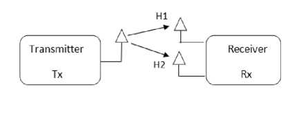
Fig.1. Receive diversity has two receiving antennas.
Transmit diversity: Transmit diversity is obtained by using several antennas at the transmitter side of communication link. Transmit diversity method is far more beneficial as compared to receive diversity. This is achieved owing to the truth that generally the number of receivers is greater than the number of transmitters. The method of transmit diversity is a modern phenomenon [2]. Transmit diversity shows in Fig. 2 having two transmitting and one receiving antenna.
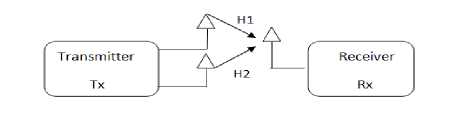
Fig.2. Transmit diversity has two transmitting antennas
-
IV. Impimentation Model
The work flow diagram given in fig. 3 the source provide the input to encoder and then the information is interleaved and pass through the channel , at the receiver side the data is deinterleaved and decoded and pass it to error calculator .
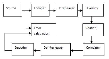
Fig.3. Block diagram of MIMO Diversity using Encoder, Interleaver, and Modulator at the transmitter.
A. Alamouti’s Transmit Diversity Technique
The receive diversity was simpler and receiving devices producing no interference .hence it was widely used from the past .Transmit diversity was complicated because of the two reasons:
First: The several signals from the transmitter end would combine to generate only a single value of signal at a specified point resultant is no diversity.
Second: The signals from the transmitted side would sometimes produce obnoxious nulls in the emission of signal at some angle.
Alamouti proposed a scheme that utilizes [7] both time and space diversity is called space time coding [7]. Alamouti states that “The scheme using two transmitting antennas and one receiving antenna provides the same diversity order as the scheme using one transmitting and two receiving antennas i.e. Maximum ratio receiver combining.
Two transmitters and one receiver method:
Block diagram of two transmitting and one receiving scheme in fig. 4 the signal transmission method is expressed in table 1.
Table 1. Alamouti’s transmission method.
|
time space |
…t+ 4T 1 |
t + 3T |
t + 2T |
t + T |
t |
|
Antenna 1 |
…S5 |
-S4* |
S3 |
-S2* |
S1 |
|
Antenna 2 |
…S6 |
S3* |
S4 |
S1* |
S2 |
The above table 1 shows the signal transmitted through transmitting antennas at different time slots.
The alamouti’s receiving equations are expressed as:
r1=r(t)=h1S1+ h1S2+n1
r2=r(t+T)=-h1S2*+h2S1*+n2
The combining schemes are defined in equation 3 and 4
S1=h1*r1+h2 r2*(3)
S2=r1*r1-h1 r2*(4)
After that these combined information’s are sent to Maximum Likelihood Detector (MLD) for all information it uses decision rule method as d2 (S1, Sk) <= d2(S1, Sl ) for all k ≠ l(5)
the resultant combined information from equations 3 and 4 are same as the received signals from both the branches of maximum ratio receiver combining (MRRC), Si is selected when
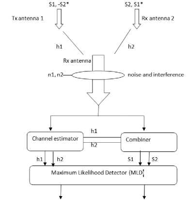
Fig.4. Alamouti’s diversity scheme with two transmitter and one receiver.
d2 ± S 1 , (α 1 2 + α 2 2) S k )<= d2(S 1 ,(α 1 2+ α 2 2)S l ) (6)
B. Four transmitters and four receivers mimo diversity method
The 4x4 MIMO diversity technique shows in Fig. 5 is used in place of 2x1 and 2x2 diversity order because of its robustness in opposition of error effect and due to the necessity of increasing spectral efficiency together with the increasing diversity in space domain [6].
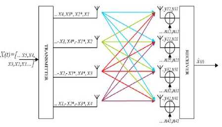
Fig.5. 4x4 MIMO Space time block code system[6]
The signal arrived during the MIMO symbol interval is follows as [8]:
Y=HX+N
Where, H is the channel matrix with 16 number of rows and 4 number of columns, it is the non squared matrix. X is 4*4 Alamouti space time block code matrix. N is noise matrix and made of non dependent, equally distributed samples of Gaussian noise. In order to achieve the combination of signals (space-time combining) at the receiving side, it is essential that the channel matrix is squared otherwise inversion of matrix, directly, cannot takes place. Though, pseudo-inversion is being employed even for the non-squared channel matrix [6].
The mathematical term of this method is as follows:
H+ = (HHH)-1HH (8)
HH is Hermitian matrix that is the transposed complex conjugate channel matrix. The resultant combining of signals in MIMO diversity is given as:
X=H+Y=H+HX+H+N=X+H+N (9)
-
C. Forward Error Correction Codes
FEC codes are used to correct some degree of errors without requesting the channel for retransmission of the bit stream [4] .FEC techniques are of two types, Convolution codes and block codes [9]. Convolution codes shown in Fig. 6 are decoded by using the viterbi algorithm. It is one of the finest decoding schemes. This algorithm is susceptible to correct the burst errors [4].
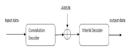
Fig.6. [10]. Block diagram of convolution encoder and decoder.
Convolution encoder: Convolution codes present an approach for controlling the errors; it is substantially dissimilar from the block codes. In this encoder, coding takes the combination of the set of input bits then these bits are stored in the fixed length of shift register. The input bits and the shift register contents perform the mod-2 addition, so that the output sequence is generated. This method is similar to binary convolution thus it is called convolution encoding [11][12]. Code rate of convolution coding is expressed as R=k/n , where k is number of input bits and n is the number of output decoded bits, m is the number of fixed shift registers, constraint length K is the number of bits on which the output of encoder depends. The state information of encoder is stored in shift registers. A convolution encoder with the code rate of ½ is revealed in fig. 7.
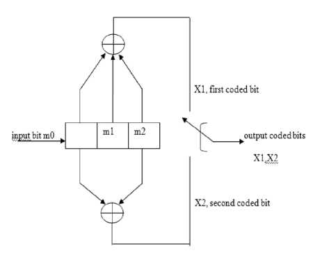
Fig.7. [4]. Block diagram of convolution encoder
Rate=1/2 ; k=1, n=2 and m=3,K=4
Here, m0 is present message bit and m1, m2 are the past message bits stored in shift register that represent the state of shift register. Rate is equal to ½ , and successive number of bits called constraint length K is 4.
-
D. Interleaving
Interleaving is standard digital signal processing method which is used to overcome the error burst in wireless communication [3].The basic approach in interleaver is to rearrange the order of symbols that is transmitted .The technique for interleaving is to disperse the sequence of the bits in bit stream to reduce the outcome of error burst that minimize the bit error rate [13].This is most effective method to minimize the error.
Basically two types of interleaver are block interleaver and convolution interleaver. In this paper, model is stimulated by matrix interleaver; it is a kind of block interleaver. Matrix interleaver shown in Fig. 8 execute by filling the matrix by taking input symbols row by row and sending the data of matrix column by column at the output port [14].
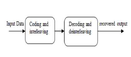
Fig.8. Block diagram of interleaving and de-interleaving.
Matrix interleaving: In matrix interleaving, the error which occurs in burst is spreading out like exhibited with respect to fading channels [13]. Having the matrix interleaving feeding is done by taking the input row by row and read the contents of matrix column by column at the output port of interleaver. At the receiving side, randomize the symbol bits after every step of decoding by using deinterleaver, thus it makes the decoding more proficient [15] .Matrix interleaver is defined by the help of n and m (n, m), where n is the number of rows and m is the number of columns. Deinterleaver takes the input symbols column by column and output is passes row by row. The tendency of matrix interleaver of burst error spreading depends upon the value of number of rows (n) and number of columns (m).
-
E. Modulations Schemes
Binary phase shift keying: The simplest form of phase shift keying is BPSK. It also termed as 2-PSK because it has two phases, separated by 1800. This modulation technique is most robust method among all PSK’s because it takes high level of distortion or noise to formulate the demodulator to make an erroneous decision [5]. It is not favourable for the transmission of high data rates. It can modulate 1 bit per symbol.
The equation of BPSK is given as[5]:
Sn (О = J^cos(27t/ c t + .(1 - n )), n = 0,1 (10)
Quadrature phase shift keying QPSK is an example of M-ary phase shift keying, it can transmit 2 bits/symbol. The phase carrier is equally spaced as 0, π/2, π, 3π/2 where all values of phases consider a unique combination of information bits. It indicates the higher order PSK implementation.
Following equation is the general form of QPSK [5]:
Sqpsк
(О = {7^ cos[(i-1)
|
]?
i
(O — 7^т[(i-1) 2 (0]} (11)
Where i=1, 2, 3, 4
Quadrature Amplitude Modulation QAM is used for both digital and analog modulation methods. It transmit two analog data signals, or two digital data bit streams through the modulation of two carrier signals by using digital modulation method ASK(amplitude shift keying) or amplitude modulation analog modulation method. These two carrier signals are usually sinusoids, and 900 out of phase from each other, hence called quadrature components or quadrature carriers. After modulation the signals are summed and the output resultant waveform is the mishmash of the amplitude shift keying and phase shift keying, or the combination of amplitude modulation and phase modulation in case of analog modulation[5].
The data is transmitted in smaller spectrum by using M-ary QAM of higher order. Errors are easily signified in symbols due to the closely located symbols in constellation diagram .Extra power is being transmitted to each symbol, so the symbol spread more and hence, it reduces the efficient power.
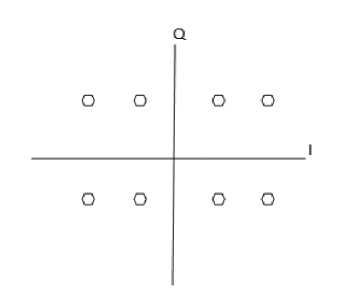
Fig.9. Constellation figure of 8-QAM modulation.
$l(0.lj^„ ... 0
+]
bt sin(2Trfc t) }
Where, i=1, 2…….M and 0 ≤ t ≤ T.[5]
-
V. Proposed Work
Analysis of simulink model based on MIMO Diversity Technique as being implemented and the respective results are shown in this section:
Part 1: Simulink diagram of Alamouti’s Diversity given in Fig. 10 for different modulation schemes.
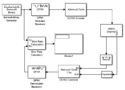
Fig.10. Implementation of Alamouti’s model in SIMULINK
In the existing research work the analysis has been done on simulink platform in which communication blocksets are used. To encourage the experiments the results were evaluated using BER calculator. Most of the results were based on different set up for example, simple modulation with MIMO, modulation, interleaver with MIMO and encoder, interleaver, modulation with MIMO.
Table 2. Alamouti based bit error rate performance
|
BIT ERROR RATE (%) |
||||
|
SNR |
BPSK |
QPSK |
8QAM |
16 QAM |
|
1 |
0.038 |
0.161 |
0.073 |
0.090 |
|
2 |
0.028 |
0.126 |
0.054 |
0.067 |
|
3 |
0.020 |
0.096 |
0.038 |
0.047 |
|
4 |
0.014 |
0.074 |
0.027 |
0.034 |
|
5 |
0.009 |
0.054 |
0.018 |
0.023 |
This table 2 is a clear reflection of results of bit error rate that is calculated that are evaluated using different modulation techniques in MIMO techniques. If a MIMO technique is implemented that is used in a simulation model then the results are best for binary phase shift keying at low SNR and also at high SNR. Now if the QPSK, technique is compared with other modulation techniques then results so calculated that is high enough for other modulation techniques, so a QPSK modulation technique is then, not preferred.
As the table3 shows that BER is reduces with increasing value of SNR. BPSK perform best and in case of M-ary, BER increases with increasing the value of M.
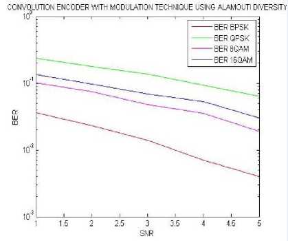
Fig.12. BER results using different SNR values calculated for MIMO alamouti diversity with convolution encoder.
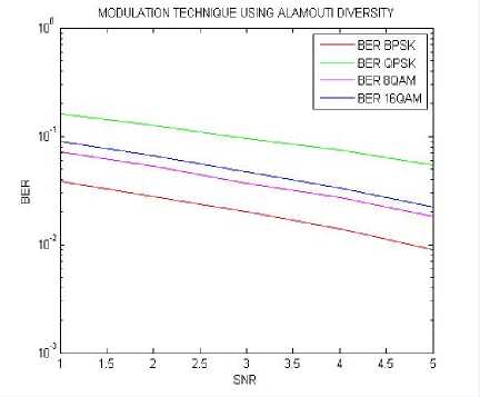
Fig.11. BER results using different SNR values calculated for MIMO alamouti’s diversity
In this fig.11 comparison of four BER results over four modulation technique for MIMO 2x1 is done. In this demonstration calculations shows that the system is almost showing a similar type of falling trend in which best performance is given by BPSK technique. In this section BER 16 QAM is giving a little bit fluctuations nearby 3 dB SNR.
Table 3. Calculation of BER for alamouti’s diversity with convolution encoder
|
BIT ERROR RATE (%) |
||||
|
SNR |
BPSK |
QPSK |
8QAM |
16 QAM |
|
1 |
0.036 |
0.238 |
0.101 |
0.135 |
|
2 |
0.023 |
0.178 |
0.075 |
0.098 |
|
3 |
0.014 |
0.138 |
0.048 |
0.069 |
|
4 |
0.007 |
0.094 |
0.035 |
0.053 |
|
5 |
0.004 |
0.064 |
0.019 |
0.030 |
In this fig.12 comparison of four BER results over four modulation technique for MIMO 2x1 with convolution encoder is done. In this demonstration calculations shows that the system is almost showing a similar type of falling trend in which best performance is given by BPSK
Table 4. Calculation of BER for Alamouti using Matrix Interleaver.
|
BIT ERROR RATE (%) |
||||
|
SNR |
BPSK |
QPSK |
8QAM |
16 QAM |
|
1 |
0.038 |
0.161 |
0.073 |
0.090 |
|
2 |
0.028 |
0.126 |
0.054 |
0.067 |
|
3 |
0.020 |
0.096 |
0.038 |
0.047 |
|
4 |
0.014 |
0.074 |
0.027 |
0.034 |
|
5 |
0.009 |
0.054 |
0.018 |
0.023 |
The above table4 is same as the table1 Hence, it shows that the results with and without interleaver are same.
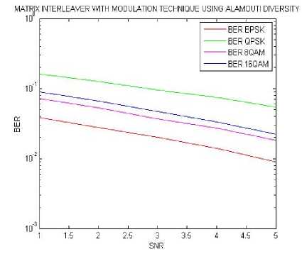
Fig.13. BER results using different SNR values calculated for MIMO alamouti diversity with matrix interleaver.
In this fig.13 comparison of four BER results over four modulation technique for MIMO 2x1 with matrix interleaver is done. In this demonstration calculations shows that the system is almost showing a similar type of falling trend in which best performance is given by BPSK
Table 5. BER performance for alamouti diversity with convolution encoder and matrix interleaver.
|
BIT ERROR RATE (%) |
||||
|
SNR |
BPSK |
QPSK |
8QAM |
16 QAM |
|
1 |
0.030 |
0.244 |
0.112 |
0.133 |
|
2 |
0.015 |
0.194 |
0.076 |
0.102 |
|
3 |
0.009 |
0.145 |
0.048 |
0.070 |
|
4 |
0.004 |
0.105 |
0.030 |
0.050 |
|
5 |
0.002 |
0.070 |
0.023 |
0.039 |
The above table5 shows the falling trend of BER with increasing SNR .
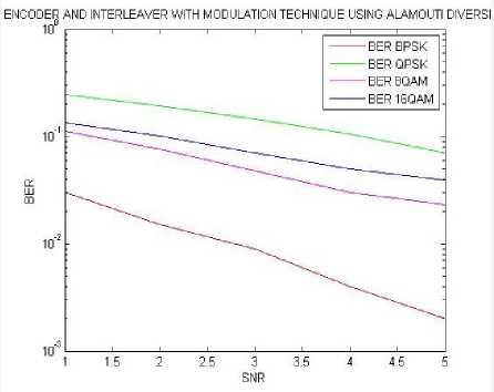
Fig.14. BER results using different SNR values calculated for MIMO alamouti diversity with convolution encoder and matrix interleaver.
In this fig.14 comparison of four BER results over four modulation techniques for MIMO 2x1 with encoder and interleaver is done. In this demonstration calculations shows that the system is almost showing a similar type of falling trend in which best performance is given by BPSK.
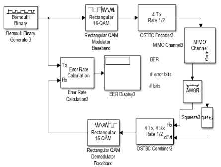
Fig.15. Description of MIMO 4x4 model
In the above fig.15, the simulink block diagram of implementation using communication block set for 4x4 orthogonal space time block coding is performed. To calculate the performance the actual implementation is seen rapidly and calculated using the same BER calculator. Best performance can be seen when 4x4 antenna combinations are used in this research work.
Table 6. 4x4 MIMO based BER performance
|
BIT ERROR RATE (%) |
||||
|
SNR |
BPSK |
QPSK |
8QAM |
16 QAM |
|
1 |
0.0190 |
0.1316 |
0.0377 |
0.0475 |
|
2 |
0.0100 |
0.0941 |
0.0202 |
0.0252 |
|
3 |
0.0046 |
0.0630 |
0.0096 |
0.0119 |
|
4 |
0.0020 |
0.0384 |
0.0041 |
0.0049 |
|
5 |
0.0008 |
0.0202 |
0.0016 |
0.0018 |
The value of bit error rate is decreases with the increasing value of SNR as shown in table6,BPSK is best modulation technique as compared to others with lower BER .
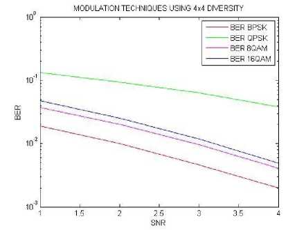
Fig.16. BER results using different SNR values calculated for 4x4 MIMO diversity.
In this fig.16 comparison of four BER results over four modulation technique for MIMO 4x4 is done. In this demonstration calculations shows that the system is almost showing a similar type of falling trend in which best performance is given by BPSK
Table 7. Calculate BER for 4x4 MIMO diversity with convolution encoder
|
BIT ERROR RATE (%) |
||||
|
SNR |
BPSK |
QPSK |
8QAM |
16 QAM |
|
1 |
0.0005 |
0.2792 |
0.0284 |
0.0802 |
|
2 |
0.0000 |
0.1717 |
0.0057 |
0.0367 |
|
3 |
0.0000 |
0.0810 |
0.0009 |
0.0140 |
|
4 |
0.0000 |
0.0263 |
0.0002 |
0.0032 |
|
5 |
0.0000 |
0.0081 |
0.0000 |
0.0005 |
With higher level of modulation techniques BER is increases as shown in table7,QPSK gives the worst performance. For higher data rates 8QAM perform better than 16QAM.
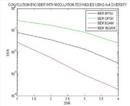
Fig.17. BER results using different SNR values calculated for 4x4 MIMO diversity with convolution encoder.
interleaver is done. In this demonstration calculations shows that the system is almost showing a similar type of falling trend in which best performance is given by BPSK
Table 9. Calculate BER for 4x4 MIMO diversity with convolution encoder and matrix interleaver.
|
BIT ERROR RATE (%) |
||||
|
SNR |
BPSK |
QPSK |
8QAM |
16 QAM |
|
1 |
0.0005 |
0.2782 |
0.0248 |
0.0809 |
|
2 |
0.0000 |
0.1645 |
0.0064 |
0.0367 |
|
3 |
0.0000 |
0.0729 |
0.0007 |
0.0116 |
|
4 |
0.0000 |
0.0248 |
0.0000 |
0.0039 |
|
5 |
0.0000 |
0.0055 |
0.0000 |
0.0006 |
BPSK of this table9 is same as table 5 .Hence 4x4 MIMO with encoder and interleaver and 4x4 MIMO with interleaver gives lower BER in case of BPSK.
In this fig.17 comparison of four BER results over four modulation technique for MIMO 4x4 with convolution encoder is done. In this demonstration calculations shows that the system is almost showing a similar type of falling trend in which best performance is given by BPSK
Table 8. 4x4 MIMO diversity with interleaver based BER performance.
|
BIT ERROR RATE (%) |
||||
|
SNR |
BPSK |
QPSK |
8QAM |
16 QAM |
|
1 |
0.0202 |
0.1322 |
0.0380 |
0.0478 |
|
2 |
0.0112 |
0.0955 |
0.0202 |
0.0251 |
|
3 |
0.0052 |
0.0639 |
0.0094 |
0.0120 |
|
4 |
0.0020 |
0.0396 |
0.0041 |
0.0050 |
|
5 |
0.0007 |
0.0214 |
0.0015 |
0.0018 |
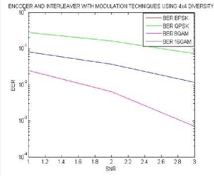
Fig.19. BER results using different SNR values calculated for 4x4 MIMO diversity with convolution encoder and matrix interleaver .
BPSK gives the best performance but having lower data rate while 8QAM perform moderately with higher data rate as shown in table8.
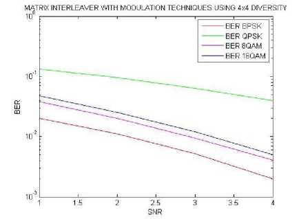
Fig.18. BER results using different SNR values calculated for 4x4 MIMO diversity with and matrix interleaver .
In this fig.18 comparison of four BER results over four modulation technique for MIMO 4x4 with matrix
In this fig.19 comparison of four BER results over four modulation techniques for MIMO 4x4 with interleaver and encoder is done. In this demonstration calculations shows that the system is almost showing a similar type of falling trend in which best performance is given by BPSK.
-
VI. Conclusion
This paper has shown three different methods of comparsion of MIMO techniques. The MIMO techniques so applied are either 2x1, also known as alamouti and 4x4 MIMO techniques. The calculation of 2x1 alamouti is done inbuilt blocksets of communication blocksets thus the system is analysed on simple modulation, modulation with interleaver, modulation with interleaver and encoder. When compared with the complexity of 2x1 and modulation blocks the results of simplest scheme of MIMO 2x1 with modulation is best. The modulation BPSK when used with interleaver and encoder and MIMO is showing best results. Similarly QPSK , 8 QAM, 16 QAM are showing good results when only MIMO alamouti is used.4x4 MIMO diversity showing best results as compared to 2x1 alamouti diversity in all different methods . In case of BPSK, the performance of BER for 4x4 MIMO with encoder and interleaver is same as the BER for MIMO with encoder method and having minimum BER as compared to other modulations and different method while in case of 8-QAM 4x4 MIMO diversity with interleaver and encoder method perform best as compared to 4x4 MIMO with convolution, MIMO with interleaver and MIMO with modulations methods.
References BER Based Performance Analysis of 2x1 Alamouti's Diversity and 4x4 MIMO Diversity with Interleaver and Encoder for BPSK, QPSK and QAM
- W. C. Jakes, Ed., Microwave Mobile Communications. New York:Wiley, 1974
- Mr. Apoorva Pandey , Mr. Rafik Ahmad, Mr. Devesh Pratap Singh" Comparison of Wireless MIMO System Under Alamouti's Scheme and Maximum Ratio Combining Technique" I.J. Image, Graphics and Signal Processing, 2013, 2, 31-37 Published Online February 2013 in MECS (http://www.mecs-press.org/)
- Anjali Kafaltiya, P S Sharma" Performance Improvement in MIMO-OFDM using BCH Coding and Interleaving" International Journal of Computer Applications (0975 – 8887) Volume 97– No.2, July 2014
- Safina Dhanda, Tazeem Ahmad Khan Malik Azizullah" Performance Assessment of Convolution Codes" International Journal of Engineering and Innovative Technology (IJEIT) Volume 3, Issue 12, June 2014
- Sakshi Gupta, Himanshu Sharma" Performance Investigation for Different Modulation Techniques in WCDMA with Multipath Fading Channels" International Journal of Advanced Research in Computer Science and Software Engineering Volume 2, Issue 7, July 2012
- Morris Filippi1, Andrea F. Cattoni2, Yannick Le Moullec2, Claudio Sacchi1" SDR Implementation of a Low Complexity and Interference-resilient Space-Time Block Decoder for MIMO-OFDM Systems"
- S. Alamouti, "Space block coding: A simple transmitter diversity technique for wireless communications," IEEE J. Select. Areas.Commun., vol. 16, pp. 1451–1458, Oct. 1998.
- T. Kaiser, A. Bourdoux, et.al. (eds.) "Smart Antennas – State of the Art", EURASIP Series on Signal Processing and Communications, Hindawi: 2005.
- Daniel J., Costello, JR., "Error Control Coding, Fundamentals and Applications", Prentice Hall, Inc. Englewood Cliffs, New Jersey, 1983.
- Rohan M. Pednekar, Dayanand B M" Design and Implementation of Convolution Encoder with Viterbi Decoder" International Journal of Emerging Technologies in Computational and Applied Sciences (IJETCAS)
- Vineet Sharma, Anuraj Shrivastav, Anjana Jain, Alok Panday, "BER performance of OFDM-BPSK,-QPSK,- QAM over AWGN channel using forward Error correcting code", International Journal of Engineering Research and Applications (IJERA) , Vol. 2, Issue 3, pp.1619-1624, May-Jun 2012.
- Vivek K. Dwivedi, Abhinav Gupta, Richansh Kumar and G. Singh, ―Performance Analysis of Coded OFDM System Using Various Co ding Schemes‖ Progress In Electromagnetic Research Symposium Proceedings, Moscow, Russia, August 18-21, 2009
- Rey, M. Lamarca and G. Vazquez, "Adaptive Interleaver based on rate- compatible punctured Convolutional codes", IEEE Transactions on communications, June 2009, Vol-57, No. 6.
- MATLAB, "HELP, Communication, toolbox, Block Interleaving.
- Zhen-dong Zhang, Bin Wu, Yong-Xu Zhu, Yu-mei Zhou, "Design and implementation of a Multi-Mode Interleaver/Deinterleaver for MIMO OFDM Systems" IEEE 2009
