Binary log design for one-way data replication with ZeroMQ

Author: I. Gede John Arissaputra, I. Made Sukarsa, Putu Wira Buana, Ni Wayan Wisswani
Journal: International Journal of Modern Education and Computer Science @ijmecs
Article in issue: 10 vol.10, 2018.
Free access
Today, many business transactions are done online, especially in the financial sector or banking [1]. But as companies grow, many problems occur such as the inability to manage data consistency, especially when data is associated with more than one database. Replication is one of the most commonly used way of syncing data. However, to ensure data remains consistent, it is not enough just to take advantage of the replication process. The problem that often happens is connection failure or offline host. The Binary Log approach is one of the alternative methods that can be used to develop database synchronization. Generally, binary log is used for data recovery or backup purposes. Binary log in the DBMS (Database Management System) record all changes that occur in the database both at the data and structure level, as well as the duration of time used. This information can be used as a reference in updating data, while the ZeroMQ socket used as data exchange medium so data in all system locations will be synchronized and integrated in real time. This research will discuss how to develop a synchronization system by utilizing Binary Log from MySQL to recognize data changes, inherit changes, send changes, and hopefully can contribute new alternative method in developing real time database synchronization.
Synchronization, Binary log, Socket, Replication
Short address: https://sciup.org/15016799
IDR: 15016799 | DOI: 10.5815/ijmecs.2018.10.03
Text of the scientific article Binary log design for one-way data replication with ZeroMQ
Published Online October 2018 in MECS DOI: 10.5815/ijmecs.2018.10.03
Today, database design for real-time applications has been widely researched. A Real-time database systems are generally known as database systems where transactions are related to deadline, right when their transactions are finished. All data elements must remain valid until the commit time, otherwise it will have a serious impact on the validity of an information [2]. Electronic data exchange between agencies or corporations must be supported with sufficient data storage capacity. MySQL database is an engine which is used to store data. MYSQL has several advantages, such as providing convenience in terms of access and can work on various platforms [3]. Data integration is an important part of distributed databases, where data from multiple sources can be integrated by implementing data integration. Distributed database systems have several advantages, such as the capability to take care of expansion (enhancement or widening) of data and data availability, as well as the capability to manage where to distribute data. Replication in a distributed database is one of several ways that can be used to distribute data [4]. However, to ensure data remains consistent, it is not enough just to take advantage of the replication process. The problem that often happens is connection failure or offline host. Data synchronization procedure or model can be used to solve the problem. Data synchronization is part of replication, this is the process to make sure every copy of the database contains similar data. The synchronization process allows data in the database to be updated in real time or periodically in other databases.
Database synchronization can be used in various purposes, such as creating audit records to record every activity that occurs in the database. The audit trails from database manipulation, enables DBA (Database Administrator) to maintain audit trails over time, to perform an access patterns and data modifications review on the DBMS (Database Management System) [5]. Binary log approach is one of several methods that can be used in developing one-way synchronization on the database. Binary log in the DBMS (Database Management System) record all changes that occur in the database both at the data and structure level, as well as the duration of time used. This information is used as a reference in updating data, while the ZeroMQ socket used as data exchange medium so data in all system locations will be synchronized and integrated in real time.
Socket is a communication mechanism that allows users to exchange data between processes or programs over a TCP / IP based network according to configuration. ZeroMQ is an open source socket library that supports concurrency framework. Concurrency is when the DBMS allows multiple transactions at the same time to access the same data. This socket supports programming languages like C, C ++, JAVA, .NET, Python and on platforms like Linux and Windows. ZeroMQ, or often known as ØMQ, 0MQ, or zmq provides sockets that transmit messages across various transport layers such as in-process, inter-process, TCP, and multicast [6].
ZeroMQ is suitable for use in this research as a medium of data exchange because it can be used on centralized, distributed, small scale, or large scale systems.
Combination of socket mechanism and information from binary logs allows the development of a customizable synchronization system that can handle problems that existed before, such as connection failure.
-
II. The Use of Binary Log
The binary log contains “events” that represent database changes that happen in the database such as the operation to create a table or data changes that occur in the table. It also contains events for statements that probably made changes to database (for example, a DELETE query which matched no rows would still recorded in the binary log), except row-based logging is used. Information regarding the length of every statement took the updated data is also recorded in the binary log. There are two general uses in the use of Binary Log:
-
1) Replication, the slave server will receive a record of data changes sent by the master replication server. The data changes is obtained from the binary log. The master server forward events containing binary log data to its slaves, then those events will be executed by the slave to equalize the data with the master.
-
2) Particular data recovery processing needs binary log data. events on binary logs that saved since the backup created will be re-executed after a backup fully recovered. These events take databases keep up to date from the backup point.
Expressions like SELECT or SHOW that do not change data didn’t recorded in the binary log. If a server running with binary logging in active state will slightly slow down the performance. Still, the advantages of the binary log that allow you to manage replication and for recovery process mostly outweigh this small performance reduction. Binary log is secure even if there is a sudden transaction termination. Only finished transactions or events are recorded or read back.
-
III. Related Research
G.Jothipriya & Shri, (2013) in their journal proposed a mobile database synchronization model using Microsoft Synchronization Framework as server. This platform was developed by Microsoft which is used to sync multiple data stores. The Sync Framework merely uses the sync agent and providers to perform the synchronization process. Case studies were conducted on employee and student systems. Employees keep student records on the server and update student information, such as exam score and behaviour records. Students get these updates and see detailed information in their app. Each time the employee updates the information in the database server, the student's mobile database is also updated using the sync technique. With this method the mobile database is synchronized with the database server and receives updates from the server [7].
Gudakesa et al., (2014) developed an application to synchronize the database using the Audit Log approach, which is Trigger on MySQL. Every table that wants to be monitored by the system, will be paired with three triggers, such as “after insert”, “after update”, and “after delete”. The data changes obtained by the trigger then recorded into a table called auditlog. The synchronization system developed in this study uses client-server architecture using socket messages as communication medium. Some of the problems encountered include the failure of the connection between the client to the server or vice versa, too much history of data changes on one audit table that affect system performance, the possibility of endless loop in two-way sync, and message security issues [4]. Another disadvantage of this method is that the structure is not dynamic. When there is a new table to be synchronized, it is necessary to create a new trigger that specifically handles table with that structure. The binary log method has more advantages in this case because data changes are obtained through query parsing, so that it is more dynamic.
Research on database synchronization design has been studied by (Surya et al., 2014) which revealed that binary logs can be used as an approach to synchronize databases. This is because the activity performed on the database recorded by the binary log in real time. The advantage of using binary logs is that configuration can be done easily for monitoring specific databases and tables, and data can be accessed via query directly. Data parsing process allows details of data changes to be obtained properly. The system developed in this study use the client-server concept where the server acts as communication mediator between clients. Some problems encountered in this study include the failure of the connection between the client with the server, the security of data sent from the client to the server or vice versa, and binary log double logging problem in two-way synchronization [2].
Lee et al., (2015) in their journal proposed a ZeroMQ-based framework to simulate distributed components. This framework allows a component on the system to communicate with other components via a ZeroMQ-based message broker. The proposed structure is able to perform cooperative simulation among model and code components, which makes it possible to incrementally implement the system. The case study used to perform the simulation is Smart Home with three components such as model-based Smart Home Model, code-based Emergency Control System and model-based Lamp Model. By using this framework, each distributed component of system can be developed incrementally on a computer and on computers. The framework can also applicable in any language and on any platform because it is ZeroMQ-based [6].
Shaochao, Sun (2010) has conducted research on data reconciliation. In their research, a MT-NT-MILP (MNM) compound method is researched for data reconciliation and gross error discovery in industrial application. The MT-NT method that has been improved is offered in order to produce gross error possibilities before data correction. Error possibilities are used to increase the efficiency by decreasing the quantity of binary elements in the MILP objective function. Examination results represent that the method is suitable mainly in the problems that have big-scale [12].
Meng, Zhaozong (2016) in his journal examines the mechanism of M2M messaging for IoT industrial applications. This study focuses on the fundamental issues in the development of distributed systems, which provide a data-oriented M2M communication procedure based on industrial system model. The main focus is on the procedure of messaging between engines for data sharing, and notification order. According to real-time data result, the tested microwave sensor module has been able to operate cross-platform, machine state monitoring, and fast data sharing, which serves as a fundamental for referenced industrial system model. The next development focus is to optimize the ZMQ messaging mechanism in establishing connections and more suitable for communication between machines [13].
Gougeaud, Sebastien (2017) in his journal, examines three problems caused by parallel execution of OGSSim that can be solved using ZeroMQ. ZeroMQ is used not only for communication tools, but also for solving problems created by asynchronism. Consequently, for both requests creation and pre-read requests processing, ZeroMQ communication sockets are used as a synchronization mechanism between the drivers and the execution module in charge of the performance metrics calculation as the response time, the device utilization, etc. Future development will focus on optimization to reduce execution time of OGSSim by replacing data structures used to store subrequests of vector type structures [14].
Estrada, Nicolas (2015) tried to compare the scalability of ZeroMQ and RabbitMQ. This study discusses the proposed prototype architecture applied in ZeroMQ and RabbitMQ, which is used to measure the impact of the number of messages over performance, and the numbers of consuming nodes over scalability. The results show that for both criteria, the degradation threshold of ZeroMQ is higher than RabbitMQ, thus more scalable and faster [15].
-
IV. Research Scheme
The general scheme of the developed system is shown in Figure 1.
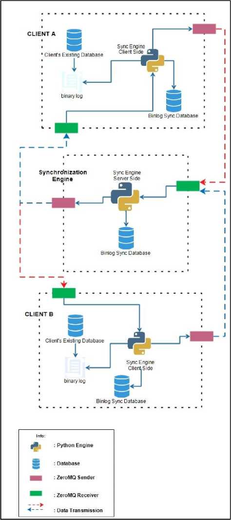
Fig.1. General Scheme
In general, the processes that occur in the developed system are described as follows. There is a computer that acts as a server to manage data transfer between clients.
Client here is a computer that wants to sync data with other client. Each client will be given a series of synchronization engine along with the database to support the operation, while the server computer will be given a different series of synchronization engine and database to support the work. Additional database on the client side are used to store incoming message data, outgoing messages, application settings, binary log contents, and process records to record the last binary log position that have been read, while the server-side database are used to store incoming messages, outgoing messages, data manipulation query from the client, and client pair details.
The first stage, the client’s computer must enable the binary log facility on MySQL. This stage is the preparation stage, the configuration must be done on the my.ini file, such as the database that want to be synchronize, and the maximum binary log size. The client side synchronization engine along with the binlog_client_db database handles and saves data changes history that occur on the client’s existing database. Data changes history in the database obtained by parsing data on binary log. The binary log records all DDL (Data Definition Language) and DML (Data Manipulation Language) activities performed by the user, but the synchronization engine will only record the insert, update, and delete related activities in the specific table that user want to synchronize.
Any data changes that occur on the client then sent to the server synchronization engine via ZeroMQ socket in the form of messages to be processed and sent to the target client by the server so data synchronization can work properly.
Socket ZeroMQ here serves as a medium of data exchange between client synchronization engine and server synchronization engine. ZeroMQ was chosen because of its reliability in handling messaging. ZeroMQ is very fast, capable of sending or receiving messages up to 4.1 million messages per second. ZeroMQ also requires only small memory to work optimally [16]. Another reason socket used in this research is because a web service can be built without the need of the hosting.
-
V. How It Works
-
A. Client
The Client Sync component is assigned to each client computer and used to manage the data changes obtained through the binary log, and send the data in message format to the server via ZeroMQ socket. The message will be sent to the destination client by the server sync component. The architecture of the client components is shown in Figure 2.
Any data manipulation performed on an existing database (client’s existing database that want to be synchronize) will be recorded in the binary log file. Binlog reader engine is used to read and store the data manipulation query into the detail log table. The incoming message processing engine then reads the log detail table, and converts the query into a message format destination client through the server. and saves it into the outbox table to be sent to the
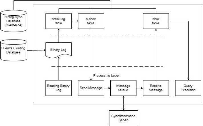
Fig.2. Client Synchronization Architecture
Every incoming message to the client is retrieved and stored to the inbox table by the message receiving engine. If the message contains data manipulation query, it will be executed by the execution_query engine so synchronization can work properly.
The Server Sync component is responsible for managing the data exchange traffic between the origin client and the target client. The architecture of the server components is shown in Figure 3.
-
B. Server
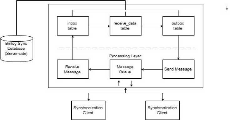
Fig.3. Server Synchronization Architecture
Incoming messages to the server are stored in the inbox table by the message receiving engine. if the message contains a data manipulation query it will be parsed and stored into the receive_data table. The next stage, the engine will find out the original client’s pair or client target of the query. Destination address, and data changes query that have been merged and formed in the message format then stored into the outbox table. The message sender engine then sends the message in serial order.
-
C. Socket Communication
ZeroMQ socket is used as a communication medium between server to client and vice versa. Inbox outbox concept is used as communication flow. Each incoming message will be directly saved to the inbox table by the message receiving engine.
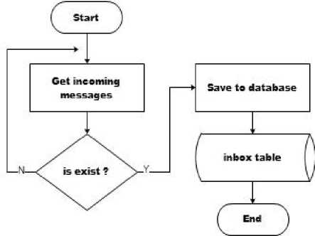
Fig.3. Receiving Message Flowchart
Messages that have been stored are processed by different engines so that the job of the message receiving engine are very concise, clear, and specific just to receive and store incoming messages.
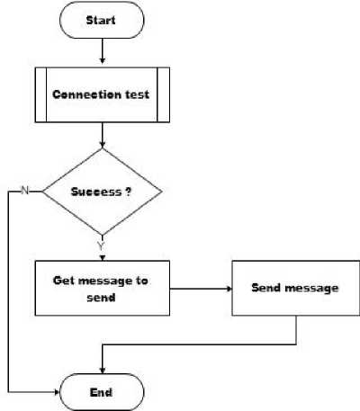
Fig.4. Sending Message Flowchart
The job of the message sender engine is also very specific, ie sending messages that exist in outbox table that have not been sent. Flag is used as a marker to find out which messages need to be sent.
There are several types of incoming messages based on their contents. Messages beginning with 1# are messages containing data manipulation queries from the origin client, while messages beginning with 3#, and 4# are messages used for connection testing purposes.
-
D. Connection Test
Connection testing is performed to ensure that the message destination (server or client) is ready to receive messages. Connection testing is always done before the sending of the message contains query data manipulation. The used method is to send a dummy message in format 3#id_outbox to the destination computer.
If the destination computer successfully receives this message, it will respond by sending a message in format 4#id_outbox. The response from the destination computer indicates that the destination computer is ready to receive the message. The original message (message containing the data manipulation query) then sent to the destination computer.
If the destination computer is not ready to receive the message, the response will not be received by the sender computer, so the original message will not be sent. The connection test will be performed every x second according to configuration, and the original message will be sent when the destination computer give response.
-
E. Reading Binary Log
The algorithm used to read binary logs accurately utilizes the index file data stored in the binary log. This index file is required to get the last query executed in the database, and used to create algorithms for the system to read only the latest binary log indexes or have not been read by the binlog reader engine.
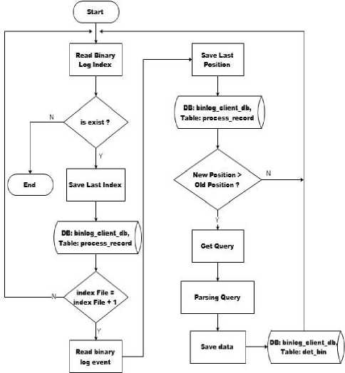
Fig.5. Reading Binary Log Flowchart
In general the process begins with reading Binary Log file index. This binary log file index is an index file that contains a list of binary log master files that have been created from data manipulation activities. The index file that will be used in the process of reading binary log files is the last recorded file. After getting the last Binary Log file, then the last position is traced, and the query is taken, so logically the last query that executed in the database is the latest query and should be sent to the destination server. The last position of the file then stored in the database as a history so the binlog reader engine will not repeat reading the same binary log.
Binary log contents can be accessed directly via query. An example of the binary log’s contents is shown in Figure 7 and Figure 8.
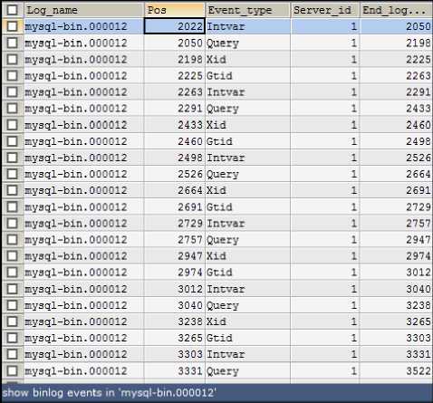
Fig.6. Binary Log Content 1
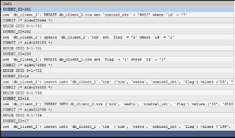
Fig.7. Binary Log Content 2
Only rows that have Intvar and Query event_type will be loaded by the engine for processing. Intvar contains the value of the primary key in the tables that have the auto increment attribute, while the Query event contains the query that already executed in the database. One database manipulation activity, recorded in only one row in the binary log. The end_log_pos field contains the last position information that will be logged to allow the engine not to repeat reading logs that have been read.
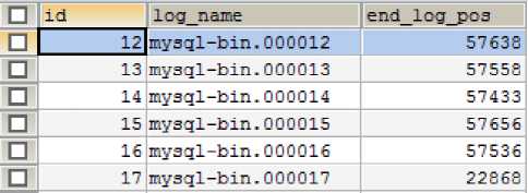
Fig.8. Process Record
The process_record table is used to store the last binary log position. When the engine reads binary logs, the engine will only read the binary log contents starting from the last log position in the process record so that only the latest data changes will be processed.
Q Q ^ ^a ln^-^-* vl * tiiti>nJ® !М®| \ < vi •**• ut> t£J
1^ Query И^^щЗ^^^^Я ^, Query = Schema Designer
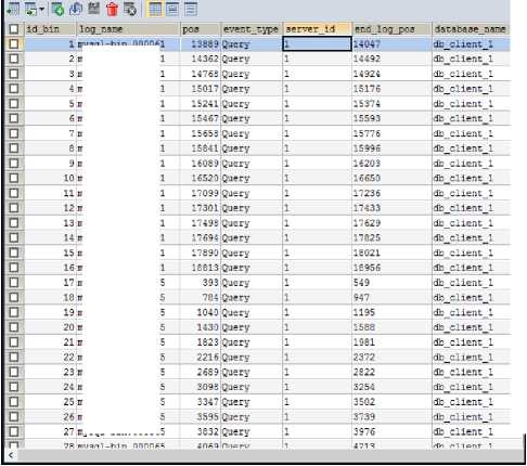
Fig.9. detail log / det_bin table 1
mysql-bin.000061
mysql-bin.000061
mysql-bin.000061
mysql-bin.000061
mysql-bin.000061
mysql-bin.000061
mysql-bin.000061
mysql-bin.000061
mysql-bin.000061
mysql-bin.000061
mysql-bin.000061
mysql-bin.000061
mysql-bin.000068
mysql-bin.00006E
mysql-bin.000068
mysql-bin.00006E
mysql-bin.000068
mysql-bin.000068
mysql-bin.000068
mysql-bin.000068
mysql-bin.000068
mysql-bin.000068
mysql-bin.000068
|
@8 ® |
|
|
I ¥ ® 0 imit rows First row 4 [O ► # of rows |1000 11 |
|
|
action |
table name info a |
|
insert |
trx insert into 'db_client_l*.'trx' ('HIM", "nominal", "flag"... 88B |
|
update |
trx update 'db_client_l'.'trx' set "flag" = 11' where "id" = 11' 60B |
|
insert |
trx insert into 'db_client_l'.‘trx' ("SIM", "nominal", "flag"... 86B |
|
insert |
trx insert into 'db client l'.'trx" ('NIM", "nominal", "flag"... 89B |
|
update |
trx update "db_client_l"."trx" set "HIM" = '19261' where "id"... 63B |
|
insert |
trx insert into "db client l'.'trx" ('NIM") values ('jdhha') 56B |
|
delete |
trx delete from "db_client_l*."trx" where "id" = '3' 48B |
|
update |
trx update db_client_l"."trx' set 'tgl' = '2017-12-13 19:02:... 77B |
|
insert |
trx insert into "db_client_l"."trx" () values () 44B |
|
insert |
tb contoh insert into "db client l".‘tb contoh' ("NIM") values ('ggg') 60B |
|
update |
tbcontoh update "db_client_l"."tbcontoh' set "NIM" = '234' where ... 67B |
|
update |
trx update ‘db client l'.'trx' set "HIM" = ’aaaa’ where 'id' ... 62B |
|
update |
trx update "db_client_l".'trx' set 'NIM' = 'bbb' where 'id' =... 61B |
|
update |
trx update "db_client_l‘.'trx" set "NIM" = 'ccc' where "id" =... 61B |
|
update |
trx update "db_client_l'.'trx" set "NIM" = ’ddd' where 'id' =... 61B |
|
tbcontoh insert into 'db_client_l*.'tb_contoh' ('NIM', "flag") val... 73B |
|
|
insert |
trx insert into 'db_client_l'.'trx' ('NIM', 'nominal", 'flag'... 86B |
|
insert |
trx insert into 'db_client_l'.'trx' ("NIM", 'nominal", 'flag'... 93B |
|
insert |
trx insert into "db_client_l'.'trx' ("NIM', 'nominal', 'flag'... 85B |
|
insert |
trx insert into 'db_client_l'. trx' ('NIM', 'nominal', 'flag'... 88B |
|
insert |
trx insert into 'db client l'.'trx' ('NIM', 'nominal', 'flag'... 88B |
|
insert |
trx insert into 'db_client_l'.'trx' ('NIM', 'nominal", 'flag'... 86B |
|
update |
trx update 'db_client_l'.'trx' set 'NIM' = '140441 where 'id'... 63B |
|
insert |
trx insert into 'db_client_l'. trx' ('NIM', 'nominal', 'flag'... 86B |
|
insert |
trx insert into 'db client l'.'trx' ('NIM', 'nominal', 'flag'... 85B |
|
insert |
trx insert into 'db_client_l'.'trx' ('NIM', 'nominal') values... 74B |
|
insert |
trx insert into 'db_client_l'.'trx' ('NIM', 'nominal') values... 74B |
|
, n ЯО T'1~ |
l"rv inqort i n^n vrib rliont 1 1 b1-w* /'NTH* ‘nnminal *1 va1i№4 74W |
Fig.10. detail log / det_bin table 2
Figure 10 and figure 11 shows the information obtained from the binary log after parsing the data. This information is recorded in the det_bin table to be processed and sent to the destination so that synchronization can run properly.
The data changes in detail log table or det_bin table are sequentially processed one by one to be sent in message form to Synchronization Server. Data processing queue mechanism is aided by flags. Flag 0 indicates that the data has not been processed, flag 1 indicates the data is being processed, and flag 2 indicates that the data has been completed and successfully converted into a message format to be sent.
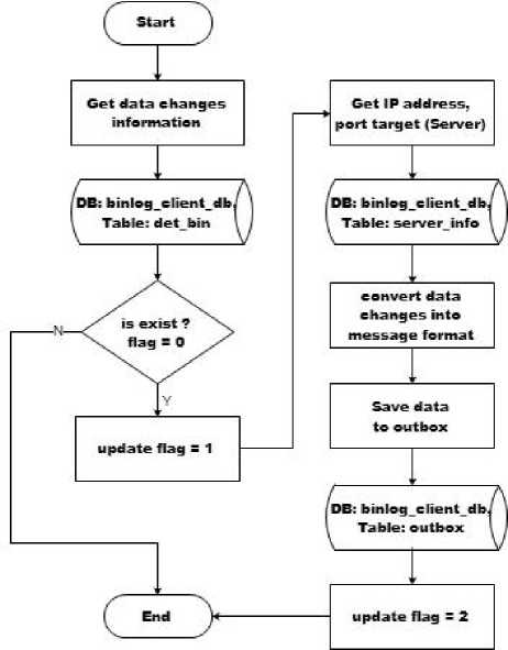
Fig.11. Data Changes Processing Flowchart
-
VI. Results
Testing is performed by measuring the time needed to synchronize data. Each host has a table named trx to be synchronized, which has a structure like in Figure 13.
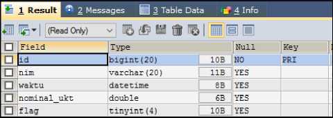
Fig.12. trx table
The contents of the trx table will be replicated in one direction from the original host to the target host. The time required will be recorded before the data is manipulated until the data is fully synced. The results is shown in Table 1.
Table 1. Result
|
DML |
Time Consumption (seconds) |
||||
|
100 data |
200 data |
400 data |
600 data |
1000 data |
|
|
Insert |
77 |
154 |
306 |
587 |
758 |
|
Update |
83 |
168 |
349 |
582 |
1175 |
|
Delete |
143 |
289 |
664 |
698 |
851 |
Table 1 shows the test results of the synchronization system that has been developed. Testing is performed in three stages, such as insert testing, update testing, and delete testing. Insert testing is done by recording the time needed to replicate x data at once. The results show that it takes 77 seconds to replicate 100 data, 154 seconds to replicate 200 data, 306 seconds for 400 data, 587 seconds for 600 data, and 758 seconds for 1000 data.
The update test is done by initializing 1000 data first, the test is then performed by recording the time required from when the update occurs until the data has been synchronized. The results show that it takes 83 seconds to replicate 100 data, 168 seconds for 200 data, 349 seconds for 400 data, 582 seconds for 600 data, and 1175 seconds for 1000 data.
Delete test is done with 1000 initial data, the test is then performed by recording the time required from when delete occurs until the data on the target host has been synchronized. The results show that it takes 143 seconds to replicate 100 data, 289 seconds to replicate 200 data, 664 seconds to replicate 400 data, 698 seconds to replicate 600 data, and 851 seconds to replicate 1000 data. If set in graphical form it will look like Figure 14.
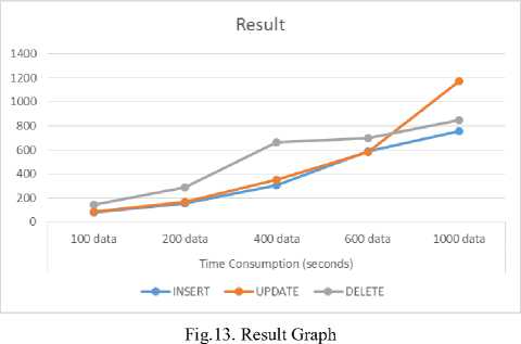
Figure 14 shows the graph of the synchronization test results. It is seen that the graph is relatively stable even though the processed data is getting larger. This indicates that the application is stable enough to handle continuous data growth.
-
VII. Conclusion
Binary Log approach can be used in developing a system for data synchronization with client-server concept according to user's configuration. The most important part is how to process information from Binary Log so that it can be utilized to build synchronization. Information from binary logs can be accessed via query commands directly and if combined with certain algorithms, it can be used for various useful things.
References Binary log design for one-way data replication with ZeroMQ
- Margaretha, F., DAMPAK ELECTRONIC BANKING TERHADAP KINERJA PERBANKAN INDONESIA. Jurnal Keuangan dan Perbankan, Vol.19, No.3 September 2015, hlm. 514–524, 2015.
- Surya, G.H., I.M. Sukarsa, and I.G.M.A. Sasmita, Two-Ways Database Synchronization In Homogenous Database Management System With Binary Log Approach. Journal of Theoretical and Applied Information Technology, 2014. 65.
- Hanafi, A., I.M. Sukarsa, and A.A.K.A.C. Wiranatha, Pertukaran Data Antar Database dengan Menggunakan Teknologi API. LONTAR KOMPUTER, 2017. 8.
- Gudakesa, R., I.M. Sukarsa, and I.G.M.A. Sasmita, Two-Ways Database Synchronization In Homogeneous DBMS Using Audit Log Approach. Journal of Theoretical and Applied Information Technology, 2014. 65.
- Abhisena, I.G.A., I.M. Sukarsa, and D.P. Githa, Implementasi Database Auditing dengan Memanfaatkan Sinkronisasi DBMS. LONTAR KOMPUTER, 2017. 8.
- Lee, S., H. Park, and W.J. Lee, Design of ZeroMQ-Based Cooperative Simulation Framework for Distributed Code and Model Components. International Journal of Future Computer and Communication, 2015. 4.
- Jothipriya and M.L. Shri, Database Synchronization of Mobile-build by using Synchronization framework. International Journal of Engineering and Technology (IJET), 2013. 5(3).
- Yang, F., et al., DZMQ: A Decentralized Distributed Messaging System for Realtime Web Applications and Services. 11th Web Information System and Application Conference, 2014.
- Malhotra, N. and A. Chaudhary, Implementation of Database Synchronization Technique between Client and Server. International Journal of Engineering Science and Innovative Technology (IJESIT), 2014. 3(4).
- Jafarinejad, M. and M. Amini, Multi-join query optimization in bucket-based encrypted databases using an enhanced ant colony optimization algorithm. Springer US, 2018.
- Patro, S., P.M. Potey, and A. Golhani, Comparative Study of Middleware solutions For Control and Monitoring systems. IEEE, 2017.
- Shaochao, S., H. Dao, and y. Gong, A MT-NT-MILP Combined Method for Gross Error Detection and Data Reconciliation. IEEE, 2010.
- Meng, Z., et al., A Data-Oriented M2M Messaging Mechanism for Industrial IoT Applications. IEEE, 2016.
- Gougeaud, S., et al., Using ZeroMQ as communication/synchronization mechanisms for IO requests simulation. 2017.
- Estrada, N. and H. Astudillo, Comparing scalability of message queue system: ZeroMQ vs RabbitMQ. XLI Latin American Computing Conference (CLEI), 2015.
- Sasongko, Y.A. and W. Suadi, IMPLEMENTASI KOMUNIKASI ANTAR SERVER PADA BISNIS PULSA ELEKTRIK MENGGUNAKAN ZEROMQ Digital Library Institut Teknologi Seputuh Nopember, 2010.
