Block Based Symmetry Key Visual Cryptography

Author: Satyendra Nath Mandal, Subhankar Dutta, Ritam Sarkar
Journal: International Journal of Computer Network and Information Security(IJCNIS) @ijcnis
Article in issue: 9 vol.4, 2012.
Free access
Visual cryptography is a method for protecting image-based secrets that has a computation-free decoding process. In this technique, numbers of shares have been generated from one image. The shares are sent through any channel to the receiver and the receiver can again produce original image by stacking all the shares in proper order. But, this method wastes a lot of bandwidth of the network. The techniques of generating shares have been used in several existing methods which are not unique. The different methods have been used in different types of images like binary, gray and color images. In this paper, a block based symmetry key visual cryptography algorithm has been proposed to convert image in encrypted form and decrypt the encrypted image into original form. The symmetric key has been generated from a real number. The encryption and decryption algorithm have been designed based on symmetry key. The algorithm with key has been used to encrypt image into single share and decrypt the single share into original image. The real number has been used to form the key may be predefined or may be sent by secure channel to the receiver. The proposed algorithm can be applied to any type images i.e. binary, gray scale and color images. A comparison has been made of the proposed algorithm with different existing algorithms like Ceaser cipher, transpose of matrix, bit comp, and transposition cipher based on the performance. The pixels distributed in original and share images have also been tested. Finally, it has shown that breaking of security level of proposed algorithm i.e. to guess the real number is huge time consuming.
Visual Cryptography, Bandwidth, Different types of Images, Security level and Symmetry key
Short address: https://sciup.org/15011116
IDR: 15011116
Text of the scientific article Block Based Symmetry Key Visual Cryptography
Published Online August 2012 in MECS
The model of secret key system, first proposed by Shannon is shown in figure 1.
In 1949, Claude Shannon[2] introduced the idea of substitution-permutation networks. This idea is the basis of modern block ciphers. The block ciphers are made of two basic operations: substitutions and permutations. The same approach has been not been used in visual cryptography. Naor & Shamir [3] have been applied the concept in images in their paper "Visual Cryptography".
They extended their new scheme to secret sharing problem. In this paper, they have planted the seed of the visual cryptography and visual secret sharing. The authors extended visual secret sharing into a visual variant of the k out of n secret sharing. They have presented a problem in which a dealer provides a transparency to each one of the n users any k of them can see the image by stacking their transparencies, but any k-1 of them gains no information about it. The basic approach was to split the image into 2 shares are generated from the original secret image and by stacking together the secret is reveal. This approach was restricted in binary images which is insufficient in real time applications. Chang-ChouLin, Wen-Hsiang Tsai [4] proposed visual cryptography for gray level images by dithering techniques. Instead of using gray sub pixels directly to constructed shares, a dithering technique is used to convert gray level images into approximate binary images. But all of the methods suffer from a severe limitation, which hinders the objectives of visual cryptography. The limitation lies in the fact that all shares are inherently random patterns carrying no visual information, raising the suspicion of data encryption. Mizuho NAKAJIMA and Yasushi YAMAGUCHI [5] proposed extended visual cryptography for natural images constructs meaningful binary images as shares.
In this paper, an algorithm has been proposed in visual cryptography without using share concept. The input image has been encrypted by image element and key value. The distribution of image gray values are in such a way that the encrypted image has been treated as single share. The encrypted image has been decrypted by same proposed algorithm. The key has been generated automatically by using a number. The value of the number has been taken from 0 to 1. This value can be pre - agreement between the sender and receiver or it can be sent by any secret means to the receiver. The result of this approach is much more secure and less bandwidth consuming. This type of efforts has not been tested earlier; this is the reason of making this paper.
-
II. EXISTING TECHNIQUE OF VISUAL CRYPTOGRAPHY
-
A. 2-out of -2 Visual Cryptography Scheme
In this concept one white or black pixel will divide into two sub pixel. One way combination of the pixel division is shown in figure 2. It is mention that the shares 1 and 2 are stacked together and get the result in the form of complete black or gray (it's partially white and black but visualizes as gray). Because of this when we stacked the shares the white in original secret image become gray in the stacked result.
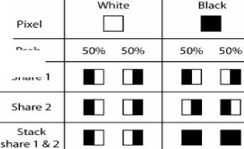
Figure 2: Basic concept of 2-out-of-2 Visual Cryptography
Prob.
Share 1
-
B. Visual cryptography for gray level images
Previous efforts in visual cryptography were restricted to binary images which is insufficient in real time applications. Chang-ChouLin, Wen-Hsiang Tsai [4] proposed visual cryptography for gray level images by dithering techniques. Instead of using gray sub pixels directly to constructed shares, a dithering technique is used to convert gray level images into approximate binary images. Then existing visual cryptography schemes for binary images are applied to accomplish the work of creating shares. The effect of this scheme is still satisfactory in the aspects of increase in relative size and decoded image quality, even when the number of gray levels in the original image still reaches 256.
-
C. Extended visual cryptography for natural images
All of the visual cryptography methods suffer from a severe limitation, which hinders the objectives of VC. The limitation lies in the fact that all shares are inherently random patterns carrying no visual information, raising the suspicion of data encryption. Mizuho NAKAJIMA and Yasushi YAMAGUCHI [5] proposed extended visual cryptography for natural images constructs meaningful binary images as shares. This will reduce the cryptanalysts to suspect secrets from an individual shares. While the previous researches basically handle only binary images, establishes the extended visual cryptography scheme suitable for natural images is shown in figure 3.
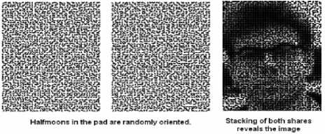
Figure 3: Example of the extended Visual Cryptography
-
D. Visual cryptography for color images
The research in visual cryptography [1] leads to the degradation in the quality of the decoded binary images, which makes it unsuitable for protection of color image. F. Liu, C. K. Wu X.J. Lin proposed a new approach on visual cryptography for colored images. They proposed three approaches as follows:
-
1. The first approach to realize color visual cryptography is to print the colors in the secret image on the shares directly similar to basic model. It uses larger pixel expansion which reduces the quality of the decoded color image.
-
2. The second approach converts a color image into black and white images on the three-color channels (red, green, blue or equivalently cyan, magenta, yellow) respectively, and then apply the black and white visual cryptography to each of the color channels. This results in decrease of pixel expansion but reduces the quality of the image due to halftone process.
-
3. The third approach utilizes the binary representation of the color of a pixel and encrypts the secret image at the bit-level. This results in better quality but requires devices for decryption. Refer to figure 4 and figure 5.
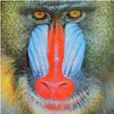
Figure 4: Original secret image Components
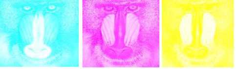
Figure 5: Primitive Color (C, M, Y)
-
III. PROPOSED ALGORITHM
-
A. Select block size
Input: Image
Output: Block size
Step 1. Store the image into two dimensional arrays or three dimensional arrays for colors image.
Step 2. Take any block from the array. The block size may be 4X2, 3X3, 4X3 elements starting from left corner of the array.
Step 3. Encrypted block size will be sent to both sender and receiver.
-
B. Key generation
Method
Step 1: To declare variables BinaryValue (an array initialized to zero), BinaryValueTemp (temporary container of bin value), x_N.
Step 2: To i nitialize a loop to put the values of BinaryValueTemp to x_N using the equation:
For index =2 to N // N=ImageHeight*ImageWidth*8 x_N = 1 - 2* BinaryValueTemp * BinaryValueTemp if (x_N>0.0)
BinaryValue [index-1] =1
else
BinaryValueTemp=x_N
End if
Next index
Step 3: To Initialize an array to hold the key and assign the value to zero initially.
formula
Step 4: To create the key array using a repetitive sum method using theBinaryValue (initialized WITH 128 VALUES)
For i= 1 to n*m // ImageHeight*ImageWidth
For j=1 to 8
Key[i] = Key[i] + BinaryValue [i*j] * 2 ^ (j-1)
Next j
Next i
-
C. Algorithm for encryption
Input: Original Image and symmetric Key
Output: Encrypted Image
Method
Step1: To retrieve the key from Key generation step.
Step 2: Assign the value of the key array using the principal diagonal approach(i.e. first row first column, second row first column, third row first column, fourth row first column, first row second column….this creates the block wise approach) to a new array FinalKey.
Step 3: To retrieve the image length and breadth and use it as index values.
Step 4: To perform bitwise XOR to the browsed image with the FinalKey value.
Step 5: Print encoded image
-
D. Algorithm for decryption
Input: Encrypted image and the real number between 0 and 1 used in key generation
Output: Decrypted image
Method
Step 1: Use the key generation step again to retrieve the Key array.
Step 2 : Assign the value of the key array using the principal diagonal approach(i.e. first row first column, second row first column, third row first column, fourth row first column, first row second column….this creates the block wise approach) to a new array FinalKey.(This is now same as the original key assigned in part 1).
Step 3: Retrieve the image length and breadth and use it as index values.
Step 4: To perform bitwise XOR to encoded image with the FinalKey value.
Step 5: Print decrypted image .
-
IV. IMPLEMENTATION
-
A. Illustrate the algorithm with example
The algorithm deals with a new aspect of image encryption and decryption regarding key generation. Here is a brief description of it.
Step 1: Let us consider a RGB image (to be encrypted) having image length n and image width m.
Step 2: Let us take a one dimensional array having (n*m*8) number of elements (here 8 refer to the block size). We call this array BinaryValue as it only takes binary values 0 and 1. For the sake of the algorithm we initialize BinaryValue to zero .For the sake of simplicity we assume n=4 and m=4.here n*m*8 = 4*4*8 =
16*8=128 is shown below
|
0 |
0 |
0 |
0 |
0 |
0 |
0 |
0 |
0 |
0 |
0 |
Step 3: Depending on a temporary variable named BinaryValueTemp we assign arbitrary values of 0 and 1 at various positions of BinaryValue. This variable BinaryValueTemp holds the entire responsibility of generating the key. We do not need to send the entire key to the receiver. Instead we only need to send the value of BinaryValueTemp. The following diagram shows some arbitrary values of BinaryValue after the operation with BinaryValueTemp x = 1 - 2* BinaryValueTemp * BinaryValueTemp
Now let us assume BinaryValueTemp=0.51537732
At iteration 1, x=0.4687724360592352 > 0.0 So 1 will be assigned at the first position of BinaryValue. The array becomes
BinaryValue (after the iteration 1)
|
1 |
0 |
0 |
0 |
0 |
0 |
0 |
0 |
0 |
0 |
0 |
0 |
0 |
UPTO 128 VALUES |
Now BinaryValueTemp is assigned to the value of x… so now BinaryValueTemp=0.4687724360592352
At iteration 2, x=0.5605048063821805 >0.0 So 1 will be assigned at the second position of BinaryValue. The array becomes
BinaryValue (after the iteration 2)
|
1 |
1 |
0 |
0 |
0 |
0 |
0 |
0 |
0 |
0 |
0 |
0 |
0 |
UPTO 128 VALUES |
Now BinaryValueTemp is assigned to the value of x… so now BinaryValueTemp=0.5605048063821805
At iteration 3, x=0.3716687240449487 >0.0 So 1 will be assigned at the third position of BinaryValue. The array becomes
BinaryValue (after the iteration 3)
|
1 |
1 |
1 |
0 |
0 |
0 |
0 |
0 |
0 |
0 |
0 |
0 |
0 |
UPTO 128 VALUES |
Now BinaryValueTemp is assigned to the value of x… so now BinaryValueTemp=0.3716687240449487
At iteration 4, x=0.7237247191335995 > 0.0 So 1 will be assigned at the fourth position of BinaryValue. The array becomes
BinaryValue (after the iteration 4)
|
1 |
1 |
1 |
1 |
0 |
0 |
0 |
0 |
0 |
0 |
0 |
0 |
0 |
UPTO 128 VALUES |
Now BinaryValueTemp is assigned to the value of x… so now BinaryValueTemp=0.7237247191335995
At iteration 4, x= -0.047554938170015 < 0.0 So 0 will be assigned at the fifth position of BinaryValue. The array becomes
BinaryValue (after the iteration 5)
|
1 |
1 |
1 |
1 |
0 |
0 |
0 |
0 |
0 |
0 |
0 |
0 |
0 |
UPTO 128 VALUES |
Now BinaryValueTemp is assigned to the value of x… so now
BinaryValueTemp= - 0.047554938170015
At iteration 4, x= 0.9954770557112921 > 0.0 So 1 will be assigned at the sixth position of BinaryValue. The array becomes
BinaryValue (after the iteration 6)
|
1 |
1 |
1 |
1 |
0 |
1 |
0 |
0 |
0 |
0 |
0 |
0 |
0 |
UPTO 128 VALUES |
This way we obtain a complete array after iteration 16…
BinaryValue (after the iteration 16)
|
1 |
1 |
1 |
1 |
0 |
1 |
0 |
1 |
1 |
0 |
0 |
1 |
1 |
UPTO 128 VALUES |
Step 4: We use a repetitive sum method to generate the key array which is a one dimensional array having the dimension (n*m). The values in the key array will range from 0 to 255.
For i= 1 to 16 [ImageHeight*ImageWidth= n*m =16]
For j=1 to 8
Key[i] = Key[i] + BinaryValue [i*j] *2^ (j-1)
Next j
Next i
The value of keys values have been furnished in table 1.
In this way 173 is assigned to the first position of the key and similarly the entire key will be created.
Key
|
173 |
36 |
39 |
64 |
... |
117 |
66 |
166 |
Step 5: In the next step we generate a two dimensional array named FinalKey having n number of rows and m number of columns. Now we will map the values of the one dimensional key array to this two dimensional FinalKey array is shown figure 6
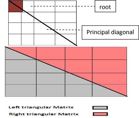
Figure 6.Mapping one dimensional into two dimensional
The principal diagonal splits the FinalKey array into two sub parts such as Left triangular matrix and right triangular matrix. In our algorithm the left triangular matrix will have higher precedence than the right subpart. For an example we have assumed the block size to be 8.so the block will contain 4 rows and two columns instead of 2 rows and 4 columns.
Let us consider FinalKey (1, 1) to be the root. So initially the principal diagonal will start from that position and Key (1) will be entered in that position. Next FinalKey(2,1) be the left most element of the principal diagonal will be selected and key(2) will be assigned to that position. This will continue in case of FinalKey (3, 1) and FinalKey (4, 1). After the completion of the first column, key (5) will be assigned to FinalKey (2, 1), key (6) will be assigned to FinalKey (2, 2) and so on. The following diagram shows the one dimensional to two dimensional mapping of key values as in figure 7
Key
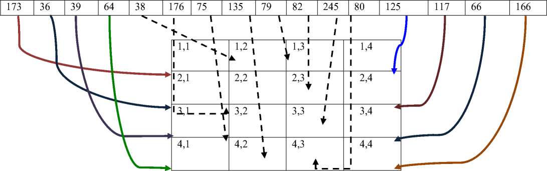
FinalKey
Figure 7. Final array from two dimensional from one dimensional
Step 6: Next we will use bitxor algorithm on the image and the FinalKey array. The encryption will be done serially i.e.
OriginalImage (1, 1) bitxor FinalKey (1, 1) = EncryptedImage (1, 1)...
OriginalImage (2, 1) bitxor FinalKey (2, 1) = EncryptedImage (2, 1)...
OriginalImage (1, 2) bitxor FinalKey (1, 2) = EncryptedImage (1, 2)... and so on…have been furnished in figure 8
Original Image
|
225 |
225 |
226 |
226 |
|
225 |
225 |
225 |
226 |
|
227 |
227 |
227 |
226 |
|
226 |
226 |
226 |
226 |
FinalKey
|
173 |
38 |
79 |
125 |
|
36 |
176 |
82 |
117 |
|
39 |
75 |
245 |
66 |
|
64 |
135 |
80 |
166 |
Figure 8. Encrypted array after encryption
Encrypted Image
|
76 |
199 |
173 |
159 |
|
197 |
81 |
179 |
151 |
|
196 |
168 |
22 |
160 |
|
162 |
101 |
178 |
68 |
Step 7: The decryption process
will be similar to the encryption process as shown below
Encrypted image
Decrypted Image
|
76 |
199 |
173 |
159 |
|
197 |
81 |
179 |
151 |
|
196 |
168 |
22 |
160 |
|
162 |
101 |
178 |
68 |
|
173 |
38 |
79 |
125 |
|
36 |
176 |
82 |
117 |
|
39 |
75 |
245 |
66 |
|
64 |
135 |
80 |
166 |
Figure 9. Decrypted array after decryption
Final Key
|
225 |
225 |
226 |
226 |
|
225 |
225 |
225 |
226 |
|
227 |
227 |
227 |
226 |
|
226 |
226 |
226 |
226 |
-
V. RESULT
-
A. The original, encrypted and decrypted image using different algorithms
The original, encrypted and decrypted images are shown in table 2 to describe the different results achieved by applying different algorithms:
-
B. Comparison based on pixel distribution
A comparison has been made between the pixel distribution of original image and the decryption image. Another comparison on pixel distributions has been made between original image and encrypted image. The comparisons have been furnished from figure 10 to 17.
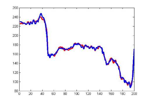
Figure 10: Comparison of original image and decrypted image of prescribed algorithm
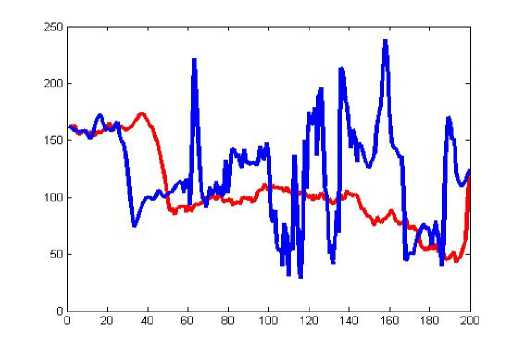
Figure 13: Comparison of original image and encrypted image of shift cipher algorithm
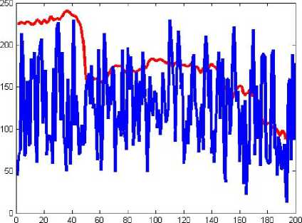
Figure 11: Comparison of original image and encrypted image
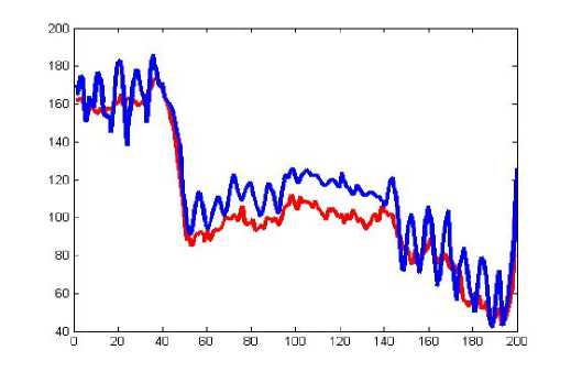
Figure 14: Comparison of original image and decrypted image
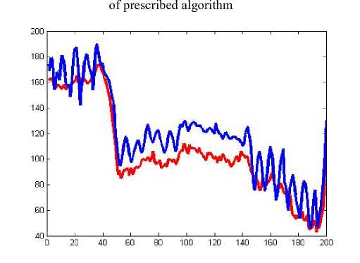
Figure 12: Comparison of original image and decrypted image of shift cipher algorithm
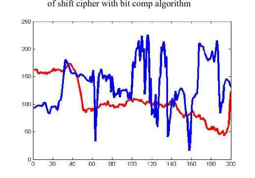
Figure 15: Comparison of original and encrypted image of shift cipher with bit comp algorithm
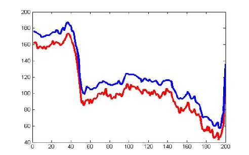
Figure 16: Comparison of original image and encrypted image of transposition cipher algorithm
combinations. Now if the algorithm takes 1 second to decrypt the encrypted image, then he will need 1010seconds to try out all the options which is approx. 2777777.78 hours i.e. 115740.740 days i.e. 317.098 years. We believe this amount of time is pretty sufficient to convince the efficiency of the algorithm.
Case 3: The most unsafe case when the hacker knows both the number of digits and also the exact value at each position, then it becomes pretty easy for him to decrypt the encrypted image and it would not take more than 1 second.
Now let us take a detailed analysis of case 2. It is assumed that the time to decrypt is one second.
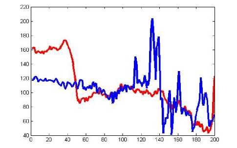
Figure 17: Comparison of original image and encrypted image of transposition cipher algorithm
Table 3: Brute Force attack analysis on the basis of Key length
|
No. of digits after the decimal point |
Time to decrypt in seconds |
Time to decrypt in hours |
Time to decrypt in days |
Time to decrypt in years |
|
3 |
1000 |
0.278 |
0.0116 |
3.17e-5 |
|
4 |
10000 |
2.78 |
0.116 |
3.17e-4 |
|
5 |
100000 |
27.8 |
1.16 |
3.17e-3 |
|
6 |
1000000 |
278.78 |
11.6 |
3.17e-2 |
|
7 |
10000000 |
2787.8 |
116 |
0.317 |
|
8 |
100000000 |
27878.78 |
1161.62 |
3.17 |
|
9 |
1000000000 |
278787.8 |
11616.2 |
31.7 |
|
10 |
10000000000 |
2787878 |
116162 |
317 |
-
C. Estimation of time to break the real number
Before referring to the brute force attack on the prescribed algorithm, we have to just summarize the factors that control the algorithm. In this case there are three factors that concern the key generation for the algorithm. They are:
-
i) The real number between 0 and 1
-
ii) The height of the image
-
iii) The width of the image
Now if any hacker gets access to the encrypted image, then it is quite obvious that he will get a direct access to the height and width of the image. So, the second and third factors are not secured. Now this leaves us with the first factor.
The real number may contain any value between 0 and 1. So, to apply any brute force attack the hacker has to sort out the following two things:
-
i) The number of digits present after the decimal point i.e. number of significant figures
-
ii) The exact value of the digit at the every position
-
Case 1: The hacker does not know the number of digits. It implies that the hacker has no clue what so ever about the number. In this case it is nearly impossible for the hacker to identify the key and decrypt the encrypted image to retrieve the original image.
-
Case 2: The hacker knows the number of digits present after the decimal points. Let us assume it to be 10. So, in that case he has to guess a total of 1010
-
-
VI. CONCLUSION AND FUTURE WORK
In this paper, a block based symmetry key cryptography has been applied to encrypt the original image into single share and decrypt the image from encrypted single share. On the basis of the observed experimental results, it has been observed that proposed algorithm has an extremely superior level of security. In compare to other algorithms, the input image has been changed completely by this proposed algorithm. The pixels of encrypted image have been distributed uniformly and the pixels in decrypted image has been distributed same as original image. It has been observed that the performance of proposed algorithm has been better than the other existing algorithms in three experiments. This algorithm has been used only single share. In visual cryptography, in order to hide the secrecy, the numbers of shares have been increased, but this affects the resolution. Therefore an optimum number of shares are required to hide the secrecy and the network traffic and overhead have been always increased. In the proposed method, the network overhead has been decreased and the image has been converted into secured encrypted image. A comparison has to be made between the proposed algorithm with other existing algorithms in respect of security, bandwidth, time and space complexity etc.
References Block Based Symmetry Key Visual Cryptography
- Uttam Kr. Mondal, Satyendra Nath Mandal, J. Pal Choudhury, J.K.Mandal, "A New Approach to Cryptography", proceedings of "International Conference Systematics, Cybernatics & Informatics (ICSCI 2008"), pp1-12.2008.
- C.E. Shannon, "Communication Theory of Security System", Bell, System Technical Journal, vol 28, pp.656-715, 1949.
- Naor, M., and Shamir, A.Visual cryptography, in ''Advances in Cryptology Eurocrypt '94'' (A. De Santis, Ed.), Lecture Notes in Computer Science, Vol. 950, pp. 1 12, Springer-Verlag, Berlin.1995.
- Chang-Chou Lin and Wen-Hsiang Tsai, Visual cryptography for gray-level images by dithering techniques, Pattern Recognition Letters, v.24 n.pp1-3.
- Nakajima, M. and Yamaguchi, Y., "Extended visual cryptography for natural images", Journal of WSCG. v10 i2. pp303-310.
