Calculation method for automatic secondary power sources

Author: Kapulin D.V., Korosteleva I.S., Pupaeva D.A.
Journal: Сибирский аэрокосмический журнал @vestnik-sibsau
Section: Математика, механика, информатика
Article in issue: 7 (33), 2010.
Free access
The article describes methods for calculating the parameters of secondary power sources (SPS): rectifying devices and voltage impulse stabilizers. Algorithms for calculating parameters of SPS power circuits have been developed.
Secondary power sources, algorithms for calculating the parameters of secondary power sources
Short address: https://sciup.org/148176472
IDR: 148176472
Text of the scientific article Calculation method for automatic secondary power sources
Secondary power sources (SPS) are an integral part of any radio set. Modern SPSs of electronic equipment have developed far beyond the class of simple radio-electronic devices, containing a small number of elements as it was 25– 30 years ago. Today the secondary power sources are fairly complex devices which contain a large variety of functional units, performing certain functional transformations of electrical energy improving its quality. All this demands constant increase of performance from the SPS, while the time requirement for the design of the SPSs is being reduced. Electronic circuits of SPSs are characterized by a presence of components with nonlinear characteristics.
The calculation of these circuits represents a significant challenge not only for manual exploit, but for computer operation. Nevertheless, there are methods of SPS approximate calculations that allow with sufficient accuracy to determine the main parameters of the projected scheme.
Analytical calculation of rectifying device parameters and voltage stabilizers represents a significant difficulty when applying a manual approach. Existing computer-aided calculation schemes enable SPSs with sufficient accuracy for engineering practice to determine the main parameters of the projected scheme. However such tools are calibrated to a particular class of circuits, such as specific types of rectifiers, stabilizers, converters, and other devices [1].
Therefore, the purpose of this article is to research methods of calculating the basic schemes for rectifying devices and voltage impulse stabilizers, as well as the development of algorithms for future program implementation, which would allow the calculation of parameters for basic SPS types (rectifying devices and voltage stabilizers), electronic equipment without the use of other software funds.
Methods and algorithms for calculating the parameters of secondary power sources.
The function of a rectifier device is the transformation of AC to DC (which is used for various electronic power devices). The design of the rectifier is reduced according to the selected scheme and type of valves, the valve calculation mode, the effective values of currents and voltages of the transformer windings, and the features of the smoothing filter. Fig. 1, 2 shows the basic circuits of rectifiers used to power electronic equipment.
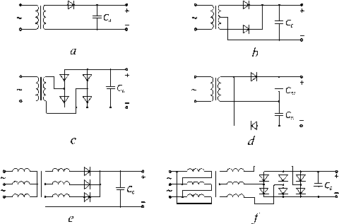
Fig. 1. Rectifiers operating at capacity:
a – half-wave circuit; b – full-wave circuit; c – full-wave bridge circuit; d – double-voltage circuit; e – three-phase circuit;
f – six-phase (Larionov) scheme
Generally all the elements of the rectifier unit should be computed in a complex, because each successive element significantly affects the behavior of the previous as well as of the subsequent scheme (element) block. For example, a smoothing filter can dramatically change the mode of operation and the estimated ratio of currents and voltages in a circuit of valves and transformers.
Nevertheless, in many cases it is preferable to calculate each block of the device separately, specifying, and considering the extent to which it affects the mutual influence of the modes’ other circuit blocks, using data from the calculation of one block as an input for subsequent calculations for the following and previous blocks. For example, in result of the rectifier calculation (meant for obtaining source data for the transformer calculation) and the smoothing filter, the smoothing filter calculations can be applied to obtain the necessary data for calculating the rectifier and voltage stabilizer.
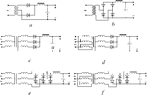
Fig. 2. Rectifiers operating at inductance;
a – full-wave circuit; b – full-wave bridge circuit; c – three-phase circuit; d – three-phase circuit; e – six-phase (Larionov) scheme; f – six-phase (Larionov) scheme
The initial data is required to count the value of the output voltage and the current for given admissible values of the pulsation coefficient. It also considers the conditions for rectifier power access, given the additional operational requirements and properties of the calculated rectifier device. In the process of calculating individual blocks it is essential to compare the obtained data with that known or obtained by calculating the blocks in a scheme of pre-computed clusters.
The method of calculating a rectifier device depends on the operating modes of the device and its type. Similar methods of calculating various types of rectifiers are given in [1–4]. Currently, electronics equipment widely uses rectifying devices with an inductive and capacitive load response for power. To calculate the rectifier a with capacitive load response a method based on approximate graph analytical calculations is used. The following data is implied:
-
– rectified voltage E 0 ;
-
– rectified current I 0 ;
-
– coefficient of pulsation a p 0 ;
-
– supply voltage U с ;
-
– voltage frequency f .
The same method is used when calculating any similar scheme. The method given in [1] is for automated use. The only difference in these schemes is in the varying coefficients Ki in the formulas. The coefficients introduced in the calculation method (for the convenience of automation) and do not play a significant role in understanding the algorithm. For each scheme, these factors have an impact; they are given in [1].
After choosing a desired scheme, we proceed to the evaluation of the valves. The average direct current of the diode:
I v = K i l o . (1)
and calculate the surge current of the diode:
I m = , . (14)
K 3
Power allocated on a valve when the current flows in a forward direction:
There are approximate formulas for reverse voltage and pulse current of the diode, but their exact values can be obtained after calculations of the transformer. The calculation begins with the definition of the transformer’s induction: B Т . An approximating formula is used for software implementation:
P all
I d ■ 0,2
I 0 v .
The required value of filter capacitor is calculated:
С о =
B Т = 1.2 – 0.4 sin(0.003 E 0 I 0 ). (2)
r ■ a p o ■ f ’
Then the resistance phase of the secondary winding are calculated:
rT = K 2
I 0 fB Т
fB T 4 . E 0 I 0
The rectifier phase resistance:
r = K 8 R i + r Т , (4)
where R i ≈ 0,2/ I 0 v – is the internal resistance of valves. Next the auxiliary parameter is defined:
A o = tg ®-® П' , . (5)
K 3 E 0
Solving the transcendental equation: tgΘ – Θ = A 0 , it is possible to find the current cutoff angle Θ. In order to find Θ in software implementation, a numerical method dividing the segment in half is used. The EMF of the secondary winding of the transformer is:
U 2 х
K 4 E 0 .
V2 cos ®
Then we define the auxiliary coefficient:
^n [ ® ( 1 + 0,5 cos 2 ® ) - 0,75 sin 2 ® ]
0 sin ®-® cos ® ,
the effective current of the secondary winding:
I 2 = K 5 D 0 I 0 , (8)
the effective current primary winding:
K 10 I 0 U 2 х U с
The overall capacity of the transformer is:
P ovr « K 7 P o = K 7 E o I o . (10)
Then we define the diode parameters. Reverse voltage of the diode:
U rev = K 9 U 2 x . (11)
Efficient diode current:
I d = K 6 I 2 . (12)
The support coefficient F 0 :
л (1 - cos ® ) sin ® - ® cos ® ,
where H f – is the auxiliary factor depending on the angle Θ and the number of rectification phases (coefficient K 3 ) [1]. It is counted by:
H f = 25330 ■ (2 ®- sin2 ® ) ■ cos ® , (17)
if K 3 = 1, or:
H = 101000 ■ [sin( K 3 ® ) ■ cos ® - K з ■ cos( K 3 ® ) ■ sin ® ] f " K 3 ■ ( K 3 2 - 1) ■ cos ®
, (18)
if K 3 > 1. For calculation the internal resistance of the rectifier is necessary to define the intermediate point of the load characteristics:
„ U 2r V2cos ®
E = -------- ,
K 4
I = 0.45 ■
[ . ® ® ®
K U, v ■ sin----cos — 3 2 : ( 2 2 2
K 4 ■ r
Then internal resistance of the rectifier is:
Rr = E^E o r 1 0 - 1
.
Calculation of rectifiers with inductive loads is similar to the aforementioned method. The following inputs are required for the calculation:
– rectified voltage E 0 ;
-
– rectified current I 0 ;
-
– pulse rate at the filter output a p 1 ;
-
– supply voltage U l ;
– voltage frequency f .
Differences in the calculation scheme are only in the various coefficients Ki in the formulas. For each scheme, these factors have certain significance; they are given in [1].
The calculation begins determining the parameters of the transformer. First, we find the induction B Т and the resistance r Т of transformer. Leakage inductance of the transformer:
L S = K 13 ■
E 0 1
I 0 fB T 4 fBT
E 0 I 0
Then the rectified voltage at idling is:
E 0 x = E 0 + A E r + A E x + A E B ex + \ E thr , (23)
where voltage drop across the active resistance of the transformer A E r = K 2 1 0 r T , at reactive - A E Х = K 3 1 0 f L S , at valves in circuit - A E b СХ = K 4 -A EB « K 4 - 0,6; voltage drop during throttle A Ethr « 0,005 - E 0. The EMF of the secondary winding of the transformer is:
U2х = K6 E0х.(24)
The effective secondary current:
I2 = K7 I0.(25)
The effective primary current:
I1 = K 14 I0 n,(26)
where n = U 2 х / U 1 – is the transformation ratio. The overall capacity of the transformer is:
Povr = K9 E0х I0.(27)
The parameters of the diodes. The reverse voltage of the diode is equal to:
Urev = K5 U2х.(28)
The average forward current of diode:
I0v = K1 I0.(29)
exceptions, the difference in calculation for the two types of reaction load (inductive and capacitive) differs in coefficients Ki in the formulas. Some of these factors depend on the value of the main calculations of the duty cycle p ; it is desirable to calculate them in advance. The values and formulas for calculating the coefficients are presented in [1]. The remaining differences between the calculations for the capacitive and inductive load reactions are described as the methodology.
First, we determine the resistance of the transformer:
r T = K 1 -
1.2 E 0 f I 03
Then we find the EMF of the secondary winding: U 2 х = K 2 E 0 + K 3 r Т I 0 + K 4 , and the overall transformer power:
P ovr = 1.1 - U 2 x I 0 K 5 .
The effective secondary current:
The forward pulse current I m = I 0 . Diode power dissipation:
P d = A E b 1 0 v « 0,6 1 0 v . (30)
The effective primary current:
1 1 = 1.1 - K 7 1 0 n ,
The minimal throttle inductance:
L thr min
2 E 0
( K 32 - 1) K n fl 0 ,
then the filter capacity:
С =
q p -10 6
K 32 - 4 n 2 f2LT min
where n = U 2 х / U l – is the ratio of transformation.
We define the parameters of the diodes. The reverse voltage of the diode is:
U rev = 2 K 8 U 2 х .
The average forward current when calculating diode rectifier devices with inductive load response is calculated using:
where q p = a p 0 / a p 1 = K 10 / a p 1 , a p 0 – rate fluctuations at the filter input (constant for this scheme). The capacitors’ operating voltage must be calculated during idling rectifier, i. e. U w > E 0 x c > 0 = K 11 U 2 x , where E 0 x c > 0 - is the rectified circuit voltage at C > 0.
The internal resistance of the rectifier is:
I = I2 0 v 2 , in the case of a capacitive load reaction:
I I 0 K 9
0 v 2
.
R r
E 0 х
-
I 0
The critical point of the load characteristic is
determined by:
I 0 cr
( K 32 — 1) K n fL », min
The forward pulse current of the diode:
I m = I 0 P K 9 .
The diode’s power dissipation:
Pr = K 10 I 0.
We then compute the capacitance inductive load is equal to the reaction:
(45) filter. With
U 0 cr = E 0 + ( 1 0 - 1 0 cr ) - R r . (35)
To calculate the rectifier, supplied by rectangular voltage, the initial data for the calculation technique [1] is:
-
– rectified voltage E 0 ;
-
– rectified current I 0 ;
-
– pulse rate a p ;
-
– supply voltage U l ;
-
– voltage frequency f ;
-
- duty cycle p .
Below is a generalized method of calculation for a case of inductive and capacitive load reaction. With a few
С = 10 7 - 1 0
4 n 3 a pE 0 f
.
In a case of capacitive reaction load, the capacitance is calculated by:
KqL - K e- sin I — I- 10 5 9 0 9 I K , PJ
С =-------------
2 a p E 0 f
.
When calculating the response of the rectifier with an inductive load, we still must calculate the inductance of
the throttle and the internal resistance of the rectifier. The throttle inductance:
E o P sin П
L hr = 0,1 . (48)
I 0 f
The internal resistance of the rectifier:
Rr =
U 2 x - E 0
. K 4
A method for computing VIS power circuits is presented in table. In addition to these parameters it is necessary to determine the capacity of the filter. It is calculated differently for each type of stabilizer. Calculation can be started after the determination of the critical inductance throttle L . The next method is for decrease-type VIS calculations. First we determine the coefficient of the smoothing filter Q :
E o ■
Voltage impulse stabilizers (VIS) along with the voltage rectifiers also are widely used in power radioelectronic equipment. The advantages of VISs, compared to continuous stabilizers, are high efficiency, small size and weight, and high power density; hence there is a widespread use of VISs in the design of autonomous power facility systems. The VIS power circuits are shown in fig. 3–5.
There are different methods for calculating the parameters of the VIS power circuits [1; 4]. The initial data for calculations is:
-
– input voltage E in ;
-
– output voltage E 0 ;
-
– operating frequency f ;
-
– voltage fluctuations U p ;
-
– pulse rate ap ;
-
– minimum I min and rated I 0 load currents.
2.2
-
2.5
■
Q =

U p
-
0.1
The inductance produce on the capacity of the filter is:
x ( N ) = Q ),
where N – is the number of filter links. Then the capacity of the filter is:
C ( N ) = XLN ).
The amplitude of voltage fluctuations can be calculated by:
f 1 -1
U p max ( N ) = U p ■ Q ( N J . (53)
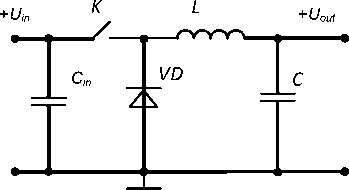
Fig. 3. Decrease-type VIS
For increase-type VIS the capacity of the filter is determined by:
10 6 ■ I o ( E o - E „ ) fE 0 U p
+
L
VD
+ U out
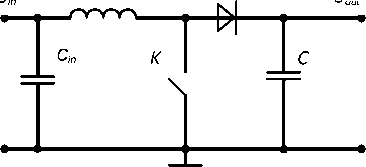
Fig. 4. Increase-type VIS
–
K
VD
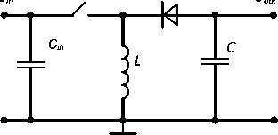
Fig. 5. Invert-type VIS
For invert-type VIS the capacity of the filter is:
C =
10 6 ■ I o E o f ( Em + E o ) Up ’
and capacity of the input filter is:
10 6 ■ I o E o fa p Em ( E n + E o ) .
Using the aforementioned computational procedures (1–56), we have developed algorithms for calculating the parameters of pulse rectifiers and voltage stabilizers, which are graphically presented in fig. 6–9.
Algorithms for the calculation of rectifying devices include a number of restrictions at the input data under which the obtained result has a sufficient degree of accuracy. If certain terms are violated the algorithm will provide output data which will reduce accuracy. The diagnosis of the entered data for correctness is carried out after the entry procedure.
There are following limitations to the input data:
-
– inappropriate negative figures;
-
– output power ( E 0 I 0 ) should not exceed 500 W;
-
– output voltage E 0 not less 3 V;
-
– maximum frequency voltage f is 5 kHz;
-
– for fullwave three-phase circuits the rate fluctuations ap 0 must be less than 0,07.
Methods for calculating parameters of voltage impulse regulators
|
Measured parameter |
VIS type |
||
|
Decrease |
Invert |
Increase |
|
|
Critical throttle inductance L |
500 E 0( E „ - E 0 ) |
500 E 0 E i 2 n |
500 E in ( E 0 - E n ) |
|
fI 0 E in |
fl min ( E in + E 0 ) 2 |
f I min E 02 |
|
|
Average throttle current I tr |
I 0 |
1 0 ( E in + E 0 ) / E in |
I 0 E 0 / Ein |
|
The variable component of the throttle current I tr ~ |
E o ( E in — E 0 ) 2 fE in L |
E in E 0 2 f ( E in + E 0 ) L |
E nn ( E 0 - E n ) 2 fE 0 L |
|
Amplitude of collector current I k max |
I thr + I thr ~ |
||
|
Effective collector current I k |
I 0 EE i 0 n |
-^ EE 0( E 0 + E n ) Ein |
I E0E 0 ( E 0 - Eta ) Ein |
|
Collector-emitter voltage U ke |
E in |
Е in + Е 0 |
Е 0 |
|
Power dissipated transistor P tr |
( ^e.A Ik \ 0.07 • E ,.„ + —° k V E n ) |
< ^ Ik 0.07( E + E o) +----5- V E n + E 0 ) |
IkE 0 (0.07 E ^ + 2) E in |
|
Average diode current I d |
I E in - E 0 0 in |
I 0 |
I 0 |
|
Reverse diode voltage U rev |
E in |
Е in + Е 0 |
Е 0 |
|
Power dissipated diode P d |
0.8 • Id E i" - E 0 d Ein |
0.8 • E— 0 U rev |
|
|
Input stabilizer current I in |
E 0 I 0 + P r + P d E in |
||
|
Efficiency n |
E 0 I 0 E in I in |
||
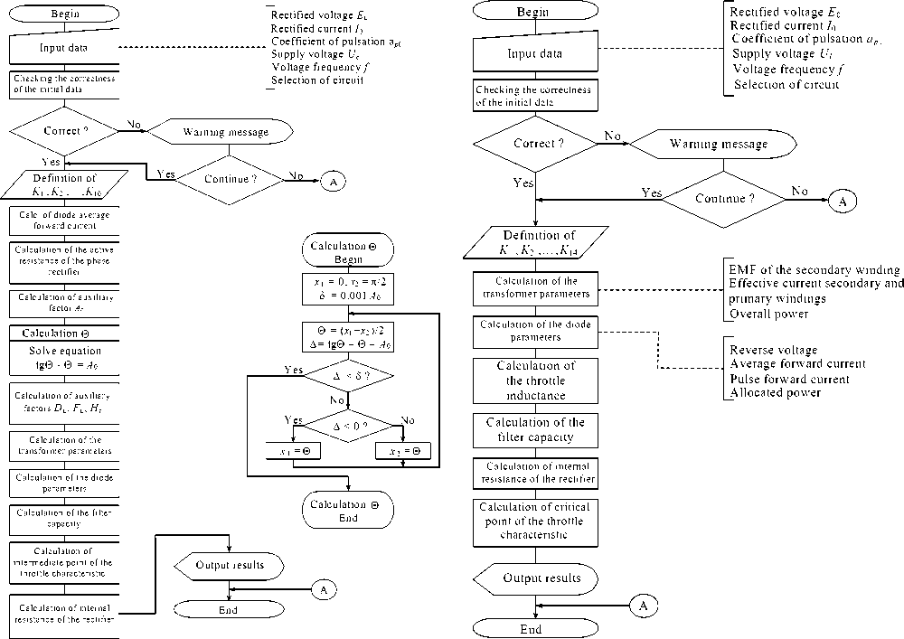
Fig. 6. Algorithm for calculating the parameters of the rectifier with capacitive load reaction
Fig. 7. Algorithm for calculating the parameters of the rectifier with inductive load reaction
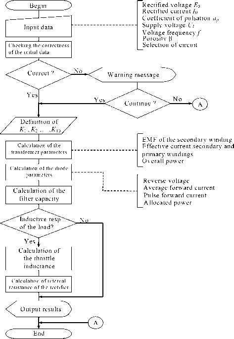
Fig. 8. Algorithm for calculating the rectifier account settings, fed by rectangular voltage
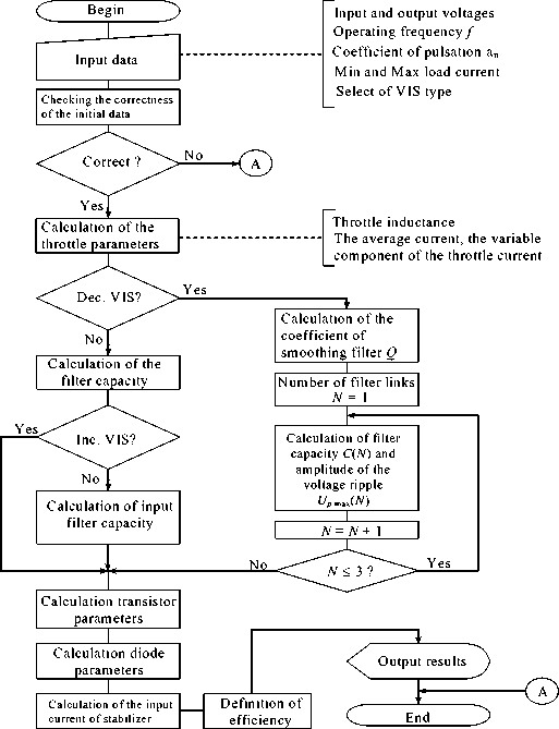
Fig. 9. Algorithm for calculating the parameters of the voltage impulse stabilizer
If the there are negative figures in the initial data, there will be errors that shall make further calculation impossible. If other conditions are violated, there will be a warning of reduction in accuracy for the result and the necessity to precede further calculations.
An algorithm for calculating the parameters of the voltage impulse stabilizer after initial data input is carried out to check the preciseness. The following conditions are checked:
-
– negative figures are not allowed in the original data;
-
– input voltage for decrease-type VISs Ein must be greater than the rectified voltage E 0 ;
-
– on the contrary, input voltage for increase-type VISs E in must be less than the rectified voltage E 0 .
If any of these conditions are not observed, the result will occur in an error message, making further calculations impossible.
In the article, each of the main secondary power sources have been presented with a summarized methodology of power circuits parameter calculations. For rectifying devices the key parameters are those of the transformer, diodes, the filter, internal resistance of the rectifier, voltage impulse stabilizer, parameters of the throttle, diodes, transistors, and filters.
The developed methods of calculation had been used to form algorithms for accounting rectifying devices and pulse voltage stabilizers. The developed algorithms have a sufficient accuracy for engineering practice (deviation of the calculation results, using software applications does not exceed 5–7 % compared to manual calculations for any of the reviewed devices); this has been confirmed by MathCAD simulation. The developed algorithms will dramatically reduce the required time for designing electronic devices, and reduce the total number of design errors by automating routine operations for accounting pulse rectifiers parameters and voltage regulators of various types.
